13 |
P a g e
SECURITY IN COGNITIVE RADIO NETWORK
Lakshmi Ganesh.R
1, Srinath.R
2, Nithin Thomas
3,
Beulah Hemalatha
41, 2, 3
UG Student,
4Asst. Professor
Dept. of Electronics and Communication Engineering, Bharath University,(India)
,
ABSTRACT
A Software defined radio is a radio which can tune to any frequency band. It has an ability to transmit and
receive different modulations and different physical parameters across the large frequency spectrum by
programmable hardware and software. An SDR performs significant amount of signal processing in a general
purpose computer on a reconfigurable pulse of digital electronics on the combination of both.The platform to
transmit and receive the OFDM radio signal is using QPSK and BPSK. In Hardware Radio Quality of Service,
PRR and Td will be small compared to Software Defined radio
Keywords – SDR, QPSK, BPSK, OFDM, QOS, PRR
I. INTRODUCTION
Software Defined Radio is used for communication in a most secured way. Hardware alone is used for
designing the existing system for the radio frequency transmission where the transmission must be in fixed
frequency, modulation and parameters. This technique cannot be used for multi frequency transmission.
Transmitter and receiver need separate antenna. Because of using the hardware alone, impedance matching must
be considered. Impedance matching should be achieved to obtain maximum gain. It may result in hacking of
Information, Software Injection, Hardware Injection and Interference. In case of any improvisation in design
might result in more expense as the entire design is composed of Hardware‘s.
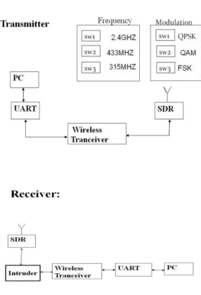
II. PROPOSED SYSTEM
In this proposed system, the modulation block and parameters are replaced by software using embedded ‗C‘. A
user interface is designed using Visual Basic which allows us to select the desired Modulation, Algorithm and
the frequency based on the requirement. It reduces the cost of hardware and up-gradation as the major part of
14 |
P a g e
Figure 1: Transmitter and Receiver of Proposed Design2.1 Working of the proposed system
The proposed system requires Hardware such as ADC/DAC, Inverter F Antenna (cc250), Filter (BPF) and
Software such as Microsoft Visual Basic for User Interface and Embedded C for making modulation in
Software.
The user interface can be used to change the parameters like Modulation, Encryption method and the Frequency
to be transmitted. The modulation used in this system are QAM (Quadrature Amplitude Multiplexing)
,QPSK(Quadrature Phase Shift Keying) and FSK(Frequency Shift Keying).The Encryption/Decryption
algorithm are AES,RSA and Skip Jack Algorithm for transmitting in a highly secured manner.
2.1.1UART
A Universal Asynchronous Receiver/Transmitter is a piece of computer hardware that translates data between
15 |
P a g e
RS-232.A UART is usually an individual (or part of an) integrated circuit used for serial communications over acomputer or peripheral device serial port. They included in microcontrollers If two UARTs Combines into a
single chip called as dual UART or DUART. USART is a device which can communicate synchronously .It is
nothing but an IC provided with UART.The UART controller is the vital component of the serial
communications subsystem of a computer. It takes data in bytes and the individual bits are transmitted in
sequential fashion. At the destination, another UART collects all the bits and covert into complete bytes. Among
the transmission the parallel transmission through multiple wires is more expensive were Serial transmission of
digital information through a single wire or other medium is much more cost effective. The Main objective is to
convert the transmitted data between its sequential and parallel form at each end of the link. Each UART has a
shift register which is used for conversion between serial and parallel forms.
MAX232:
The MAX232 is an integrated circuit that transforms signals from an RS-232 serial port to signals apt for use in
TTL compatible digital logic circuits. It has a dual driver/receiver and converts the Receiver signal, Transmitter
signal, RTS and CTS Signals. The voltage level outputs (approx. ± 7.5 V) from a single + 5 V are produced by
Drives of RS-232.Using external capacitors and on-chip charge pumps the voltage is supplied to RS232. It
makes useful for implementing RS-232 in devices that otherwise do not need any voltages outside the 0 V to
+ 5 V range, as power supply design does not need to be made more complicated just for driving the RS-232 in
this case. The receivers reduce RS-232 inputs (which may be as high as ± 25 V), to standard 5 V TTL levels.
These receivers possess a typical threshold and typical hysteresis of 1.3 V and 0.5 V respectively.
16 |
P a g e
2.2 Modulation Techniques
2.2.1 QAM (Quadrature Amplitude Modulation)
Quadrature Amplitude Modulation (QAM) is both an analog and a digital modulation scheme. It conveys two
analog or digital signals, by changing (modulating) the amplitudes of two carrier waves, using the
amplitude-shift keying (ASK) digital modulation scheme or amplitude modulation (AM) analog modulation scheme. The
quadrature carriers or quadrature components are 2 carrier waves; usually sinusoids in nature are out of phase
with each other by 90°.
2.2.2 QPSK (Quadrature Phase Shift Keying)
QPSK (Quadrature Phase Shift Keying is a DSBCS modulation scheme with digital information for the
message. It sends two bits of digital information a time (without the use of another carrier frequency).The
quantity of radio frequency spectrum required to transmit QPSK reliably is half that required for BPSK signals,
which provides enough space for more users on the channel. Sometimes this is known as quadriphase Phase
Shift Keying, 4-Phase Shift Keying or 4-Quadrature Amplitude Modulation. The Basic concepts of QPSK and
4-QAM are different; the output modulated radio waves are the identical. The Constellation diagrams of QPSK
possess four points, equispaced around a circle. QPSK has an ability to encode two bits per symbol and
minimize the bit error rate (BER).
2.2.3 FSK
Frequency-shift keying (FSK) is a frequency modulation scheme in which digital information is transmitted
through discrete frequency changes of a carrier wave. The simplest FSK is binary FSK (BFSK). BFSK uses a
pair of discrete frequencies to transmit binary (0s and 1s) information. With this scheme, the "1" is called the
mark frequency and the "0" is called the space frequency.
2.3 Algorithms
The algorithm implemented for Encryption and Decryption are explained below.
2.3.1 AES:
AES is a block cipher with a block length of 128 bits. It permits three different key lengths they are 128, 192
and 256 bits. Encryption consists of 14 rounds for 256-bit keys, 12 rounds for 192-bit keys and 10 rounds of
processing for 128-bit keys. The last round in each case is exceptional, all other rounds are identical. Every
round of processing is included with one single-byte based substitution step, second step is a row-wise
permutation step, Third step is a column-wise mixing step, and finally the addition of the round key. The order
or sequence in which these steps are executed might vary from one encryption and decryption method to other.
Every stage of processing produces an output state array by working on Input state array.
2.3.2 RSA
17 |
P a g e
positive integers.An individual A who wishes to receive messages confidentially will use the pair of integers {e,n} as his/her public key. Simultaneously, this individual can make use the pair of integers {d, n} as the private
key. The definitions of n, e, and d are explained in the earlier subsection. Another party B wishing to send a
message to A confidentially will encrypt M using A‘s public key {e, n} to create cipher text C. Only A will have
access to decrypt C using his/her private key {d, n}.
If the plaintext message is too long, B may choose to use RSA as a block cipher for encrypting the message
meant for A. When it acts as a block cipher, the block size is about to reduce half the number of bits required to
represent the modulus n. The modulus required 1024 bit and 512-bit for its representation and message
encryption respectively
2.3.3 SKIP JACK
SKIPJACK is a block cipher, an algorithm for encryption developed by the U.S. National Security Agency
(NSA).Skipjack uses an 80-bit key to encrypt or decrypt 64-bit data blocks. It is an unbalanced Fiestel network
with 32 rounds. Skipjack has 32 rounds i.e. algorithm is repeated 32 times to produce the cipher text. It was
specially designed to replace the Data Encryption Standard (DES).It was implemented in tamper-resistant
hardware and its structure had been classified since its introduction in 1993.Skipjack was used to encrypt
sensitive, but not classified, government data. SKIPJACK behaves like a random function and that cipher text
bits are not correlated with either key bits or plaintext bits.
3. MATERIALS AND METHODS
This system involves three modules. They are the transfer section, collector section and the line follower
section. The introduced system is a simple and low-cost and can be easily implemented and installed in any type
of robot that can be of use in our daily life. The system will require a high frequency transformer, pulse width
modulator, inductive coils and line follower robot as their major parts for its working.
18 |
P a g e
III. RESULTS AND DISCUSSIONS
In cognitive radio, hacking is prevented by changing the modulation and frequency for an efficient
communication between sender and receiver. Changing of frequency and modulation happens because sender
and receiver have sequence of codes of data, so that even if a hacker interrupts, communication is possible. Thus
by this way a high level security is established for a data transmission through software defined radio. By this
way it is preferred using in military applications, replacing the existing JTRS (Joint Tactical Radio System).
3.1 QPSK MODULATION
Figure 4: Resultant Output of QPSK modulation
3.2 FSK MODULATION
Figure 5: Resultant Output of FSK modulation
3.3 QAM MODULATION
19 |
P a g e
3.3 FUTURE SCOPE IN SDR
The control of information security even under hacking attack can be used. This method also reduces hardware
size because of using SDR and use of smart antenna. The cost of hardware also reduced. This is also used in
military purpose.
IV. SUMMARY AND CONCLUSION OF THE PROJECT ON SDR
4.1 SUMMARY
In this thesis work the security which is one of the most important parts of any process is considered regarding
both frequency and modulation of antenna. Also the related simulation results are presented. The simulation is
done using LABVIEW AND VISUAL BASIC.
4.2 CONCLUSION
Finally, we combine the information from both physical layer and upper layer to integrate the cross-layer
mechanism. Numerical results have demonstrated that the cross-layer detection scheme can efficiently detect the
injection attack. In this thesis, security in cognitive radio is designed. Here, LABVIEW, VISUAL BASIC is
used for graphical representation and signal processing. The results are viewed in PC. From the PC the signal is
converted to serial form by means of UART. Microcontroller is used along with the wireless transceiver which
in turn secure the information by this it is been used for rescue purpose and other application.
REFERENCES
[1] K. Tan, and J. P. Oakley, ―Enhancement of Color Images in Poor Visibility Conditions,‖ Proc. IEEE Int.
Conf . Image. Proc.(ICIP2000),vol. 2, pp. 788-791, Sep. 2000.
[2] J. Kopf, B . Neubert , B. Chen, M. Cohen, D. Cohen-Or, O. Deus sen , M . Uytte daele , and D. Li chinski ,
―Deep Photo : Model-Based Photograph Enhancement and Viewing,‖ ACM Trans. Graphics., vol. 27 , no. 5,
pp.116:1-116:10, Dec. 20
[3] R. Fattal , ―Single Image Dehazing,‖ Proc. ACM SIGGRAPH‘08, 2008.
[4] K.M. He, J. Sun, and X. Tang, ―Single Image Haze Removal UsingDark Channel Prior,‖ IEEE Trans.