PROBLEMS IN FLIGHT DYNAMICS AND ITS SOLUTIONS
Ahmed Soliman M. Sherif*
Researcher, Novosibirsk State Technical University, Department of Aircraft and Helicopter
Construction, Russian Federation.
Article Received on 04/04/2017 Article Revised on 26/04/2017 Article Accepted on 17/05/2017
ABSTRACT
The mechanics of the flight studies the forces acting on the aircraft in
flight, and the reaction of the aircraft to the action of these forces. All
aircraft are equipped with a control system that allows the pilot to
maneuver and release forces from the control levers on each of the
three axes. The aerodynamic moments required to rotate the aircraft
are usually realized by deflecting control surfaces that change the
curvature of the profile. Control surfaces are located as far as possible from the center of
gravity in order to create the maximum control moment.
KEYWORDS: Coefficient of aerodynamic lift, the angle of inclination of the trajectory, aerodynamic drag coefficient of planning, the angel of decline associated with the
aerodynamic efficiency, the angle of trajectory planning.
Usually there are three independent control systems and three control surfaces - A rudder that controls the movement around the normal axis;
- Elevator, which controls the movement around the transverse axis;
- Ailerons that control the movement around the longitudinal axis
(differential spacing of the spoilers is also used).
One surface can participate in the control in two axes - Elevons - a combination of elevator and ailerons;
- The handle of the V-shaped tail, combining the functions of elevator and rudder direction;
World Journal of Engineering Research and Technology
WJERT
www.wjert.org
SJIF Impact Factor: 4.326*Corresponding Author Ahmed Soliman M. Sherif
Researcher, Novosibirsk
State Technical University,
Department of Aircraft and
Helicopter Construction,
- Differential stabilizer. When both halves work synchronously - pitch control, when
separately - by roll.
The control moment is created by creating an aerodynamic force on the corresponding
surface.
The magnitude of this force is determined by the velocity head (~V2High-speed pressure) and
the angle of deflection of the surface.
The control aerodynamic force can be created
- Deflecting the trailing edge, which will lead to a change in the curvature of the profile;
- Turning the whole surface;
- Reduce the lifting force and increase the resistance by tearing the flow with an
interceptor.
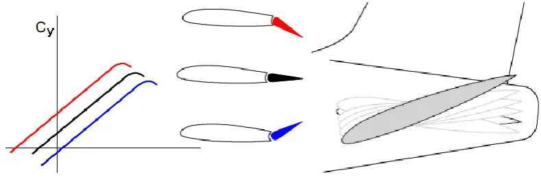
When the curvature of the profile (wing, stabilizer or keel) changes, the aerodynamic force
changes on it. The figure shows the effect of the aileron deflection on the lift factor of the
wing section.
Fig 1: Angle of attack.
Controlling aerodynamic force can be created by turning the entire surface entirely. This
scheme is often used for pitch control with the help of a one-way stabilizer. The elevator in
this case is absent.
1. INTRODUCTION
Spoilers are devices for reducing the lift force of the wing profile, by breaking the flow over
its upper surface. They are used to controlling the roll, rising on that wing, where the ailerons
Hinged moments
The aerodynamic force acting on the control surface tends to rotate this surface relative to the
axis of rotation in the direction of the force. The moment of this force will be equal to the
product of the force on the arm from the center of pressure to the axis of rotation. This
moment is called the hinge moment. The magnitude of the force is determined by the surface
area, velocity head and angle of deflection of the surface.
To deflect the control surface to the required angle, the pilot must overcome the hinge
moment by applying force to the control lever in the cab. Thus, the amount of force on the
control lever is determined by the hinge moment from the steering wheel (non- booster
control).
2. Initial data of the Research Problem Number I
For glider, flying at a height of H = 1 km and has a G = 500 kg f;
; ; :
1) Determine the value of and V (speed glider) steady decreasing at an angle of
inclination of the trajectory
2) Determine the value of and V (speed glider) steady decreasing at an angle of
3) Determine the minimum vertical upstream speed , necessary for horizontal flight
glider.
Problem Number II
Determine the minimum angle of planning when engine thrust P ≈0 proper planning speed of
the aircraft TU-124 at a height of H = 2000 m, if it is known that the aircraft drag coefficient
at this mode is equal to 0.042, the effective extension wing , and the specific load
on the wing mg/s = .
Problem Number III
Determine the derivative and the angle of zero lifting force of the aircraft, if at
and at .
Problem Number IV
Aircraft at altitude of H = 0 has a velocity , How many times is it necessary to increase the
speed at altitude of H =10 km, if the weight of the aircraft G and the lift coefficient force of
remain the same.
Problem Number V
Prove Mathematically and Graphically that, the required thrust does not equal to the force of
resistance for the aircraft and the car?
Problem Number VI
The Heavy-weight of the aircraft is , K=10, V= 200 m/s.
1) Determine the slope of the trajectory , the vertical component of the velocity .
2) Estimate, Which will have a greater impact on the increase of :
a) an increase of K by 10%;
b) an increase of P by 10%?
3. Solutions
Decision for Problem Number I
1) The equations of motion of a glider in steady planning:
planning speed
The angel of decline associated with the aerodynamic efficiency
Coefficient of aerodynamic lift
= + =3.68
= - = 0.18 (Acceptable)
Aerodynamic drag coefficient of planning by the formula
planning speed
2) The minimum angle of inclination of the trajectory of sustainable planning will be at the
maximum aerodynamic quality:
Coefficient of parasitic drag when
planning speed
3) The minimum vertical upstream speed required for steady level flight the glider will be at
glider flight at maximum aerodynamic quality:
Horizontal flight speed of the glider
The angle of trajectory planning
The minimum vertical speed
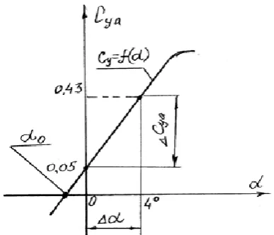
Decision for Problem Number III
The derivative is defined by the formula:
Where, is the change in the lift coefficient force of the aircraft , when the angle of
attack is changed from ;
“The calculation is made for a degree measure of the angles of attack, if the angles are
assumed in radians, then the value of must be multiplied by 57.3”
Fig 2: The calculation scheme for the solution of Problem III.
To calculate the zero lift angle, we will write the formula for determining the lift coefficient
of the aircraft on the linear part of the dependence :
Where,
Decision for Problem Number IV
When the altitude of the flight is increased, the density of air decreases, so that for constant
weight and A constant lift factor, it is necessary to increase the flight speed.
For the altitude at H = 0 we have;
Where,
For the altitude at H =10 000 m we have;
Where
When we equate these equations, the weight of the aircraft does not change.
Or
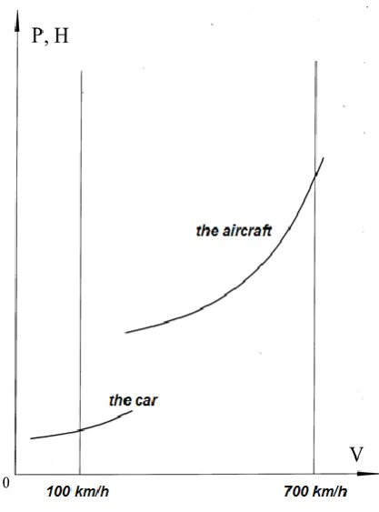
Decision for Problem Number V
The required thrust equal to the force of resistance for an aircraft and a car is determined by
the formula:
Where,
In this case we obtain:
Let's perform a trial calculation:
The car The aircraft
Result:
The ratio of the required thrust for the car and the aircraft at the same speed increased by
As we see at high speeds, the increase in resistance is much higher than at low speeds. Hence,
the curvature of the right side of the curve is sharper in the plane than in the car, since the
Decision for Problem Number VI
With a steady set of heights, the equations of motion of the aircraft have the form:
Р - Х - G*sin = 0
Y - G*cos = 0
Where, P- is the thrust of the engine;
X- is the drag force of the aircraft;
G- is the weight of the aircraft;
Y- lift of the aircraft;
- is the angle of inclination of the trajectory Moving to the horizon.
The aerodynamic quality of the aircraft is determined by the formula using the second
equation of motion
5.7 5.8 5.9
f 0.1988 0.2005 0.2023
Thus, the angle of inclination = 5.8.
We can simplify the function f, taking due to the smallness of the slope angle of
the trajectory.
As we see a simplified solution, has an error of about 1% compared to the exact solution.
Vertical component of speed
Increase K by 10% K =11.
Increase Thrust-to-weight ratio by 10%
4. CONCLUSIONS
1. In order for the aircraft to move uniformly and rectilinearly, the following conditions
must be met:
The sum of all forces directed upwards should be equal to the sum of all forces directed
downwards,
The sum of all forces forward is to be equal to the sum of all forces directed back, and
If these conditions are met, the aircraft will be in a state of equilibrium.
2. In a rectilinear horizontal flight, four forces act on the plane - lift, gravity, traction and
drag.
Gravity is applied at the center of gravity and directed vertically downwards. Gravity is
also called the weight of the aircraft.
Lifting force is applied in the center of pressure (CP), is located in the symmetry plane of
the aircraft and is directed at right angles to the flight path (the direction of the incoming
air flow).
3. In this Research, I assume that the thrust is directed in the direction of the flight path
(although this is not entirely true), and the drag is in the opposite direction.
4. The condition for uniform horizontal flight is the equilibrium of these forces. The lifting
force must be adjusted to match the current weight of the aircraft, and the engine's thrust
is selected to compensate for drag.
5. Horizontal empennage (stabilizer and elevator) is designed to create the force necessary
for balancing the pitch moments arising from the displacement of pressure centers and
gravity.
REFERENCES
1. Mkhitaryan AM Flight Dynamics. (2nd edn.), Mechanical engineering press, Moscow,
1978.
2. Salenko SD, Obuhovsky AD, Flight Dynamics. NSTU press, Novosibirsk, 2014.
3. Ostoslavsky IV, Strazheva IV, Flight dynamics. The trajectories of the