Gayathri et al. World Journal of Engineering Research and Technology
VEHICLE SAFETY SPEED CONTROLLER UNDER DRIVER
FATIGUE BY USING EYE BLINK SENSOR
1
C. Nagarajan, 2*R. Gayathri, 3M. Kalpana and 4M. Kavitha
1
Professor, EEE Department, Muthayammal College of Engineering, Rasipuram.
2,3,4
UG Students, EEE Department, Muthayammal College of Engineering, Rasipuram.
Article Received on 06/02/2019 Article Revised on 25/02/2019 Article Accepted on 17/03/2019
ABSTRACT
Accidents due to driver drowsiness can be prevented using eye blink
sensors. The driver is supposed to wear the eye blink sensor frame
throughout the course of driving and blink has to be for a couple of
seconds to detect drowsiness. Any random changes in steering
movement leads to reduction in wheel speed. The threshold of the
vibration sensor can be varied and accordingly action can be taken. The outcome is that the vibrator attached to eye blink sensor‟s frame vibrates if the driver falls asleep and also the
LCD displays the warning messages. The wheel is slowed or stopped depending on the
condition. This is accompanied by the owner being notified through the GSM module, so the owner can retrieve the driver‟s location, photograph and police station list near to driver‟s
location. This is how the driver can be alerted during drowsiness and the owner can be
notified simultaneously.
KEYWORDS: Eye Blink Sensor, GSM module, LCD.
1. INTRODUCTION
For any vehicle accidents driver‟s faults are the most accountable aspect to cause dangerous
problem to the society. Many drivers cannot control the vehicles due to different reasons it
may cause severe accidents and sometime death. For vehicle accidents various factors
wjert, 2019, Vol. 5, Issue 2, 474-483.
World Journal of Engineering Research and Technology
WJERT
www.wjert.org
ISSN 2454-695X
Original Article
SJIF Impact Factor: 5.218
*Corresponding Author
R. Gayathri
UG Students, EEE
Department, Muthayammal
College of Engineering,
Gayathri et al. World Journal of Engineering Research and Technology
understand the seriousness of fatigue driving. In India, Ministry of Road Transport and
Highway released a report in 2015, every day around 1,374 accidents may happen and almost
400 people deaths occur. Every hour because of vehicle accidents approximately 57 road
accidents and 17 people dies. In that 54.1 percent of people are in the age group of 15 to 34
years are killed in vehicle accident. The Government of India, Ministry of Road Transport
and Highway Government of India prepare a strategy to diminish the amount of motorway
accidents and losses by 50 % by 2020.
Globally vehicle accidents have seemed one of the major community health problems. In
India almost 5 lakh road accidents happened in the year 2015. A fatigue Driver those who
falls asleep at the move fails to control the vehicle, not possible to take immediate action and
results in a crash so it is necessary to monitor the drowsiness of the driver to prevent
accidents.
2. Literature Survey
Automatic driver drowsiness can be detected using artificial intelligence and visual
information. System is to detect, track and examine face and eyes of drivers for this different
real vehicle image of drivers are taken to validate the algorithms. It is a real time system
work in different light conditions. The numbers of accidents are increased due to several
factor, one of the main factor is that driver fatigue. Driver‟s sleepiness is also implemented
using video based approach. This system is noninvasive and human related elements are
used. Band power and Empirical Mode Decomposition methods are used to investigate and
extract the signal, SVM (Support Vector Machine) used to confirm the analysis and to
categorize the state of vigilance of the driver .The system designs to find the drivers
drowsiness using the hypothesis of Bayesian networks. The interaction between driver and
vehicle features are extracted to get reliable symptoms of driver drowsiness. It presents more
suitable and accurate strategies to design drowsy driver detection system .Brain and visual
activity is used in drowsiness detection system. Electroencephalographic (EEG) channel used
to monitor the brain activity. Diagnostic techniques and fuzzy logic are used in EEG-based
drowsiness detector. Using blinking detection and characterization for visual activity
Gayathri et al. World Journal of Engineering Research and Technology
3. Methodology
The concept of drowsy driver detection system focuses on the functioning of all sensor
modules used in the project. This helps explain the inputs received by modules and the
outputs they produce.
3.1 Eye Blink Sensor
This sensor module consists of the eye blink sensor frame, the IR sensor and a relay. The
vibrator device is connected to the eye blink sensor frame which is to be worn by the driver.
This vibrator vibrates whenever an accident occurs or the driver falls asleep. The frame
consists of the IR transmitter which transmits the IR rays towards the driver‟s eyes and an IR
receiver which receives the reflected rays when the eyes are closed. The relay provides the
extra current required by this module and hence is also connected to the SST microcontroller
board.
3.2 LCD
LCD is a device which displays the messages in case the driver falls asleep or accident occurs. The messages displayed are ―SLEEPING‖ and ―ACCIDENT OCCURRED‖ as per
the situation. All the modules are connected to it so that the particular signals can be received
and hence message could be displayed. It uses the power supply from the SST microcontroller board displays a ―WELCOME‖ message. It also provides 5V power to other
modules.
3.3 LM317PSU Board
This board is connected to the relay chip which in further connected to the eye blink sensor system module. This board‟s main purpose is to fulfill the power requirements of the eye
blink sensor module.
3.4 DC Motor
The motor acts as the wheel of the vehicle and it rotates when the power is supplied to it
through L298 chip. The speed of rotation is slowed down when the driver falls asleep as
detected by the eye blink sensor, in the other case the wheel is stopped when the accident
Gayathri et al. World Journal of Engineering Research and Technology
3.5 Vibration Sensor
The purpose of this sensor is to sense any jerk given to the vehicle which is the emulation of
the accident occurrence in real time. This receives power from the 5V port of the LCD.The
output produces and sends signals to dc motor driver and stops the rotation of the wheel, that
is, the motor.
4. Implementation
4.1 Hardware Requirements
The various sensors form the hardware part of the project and power supply is AC DC 12V
adapter. Other hardware modules are specified as follows:
4.2 Software Requirements
For the implementation of the modules, the coding language is specified in this part and also
the platforms used for coding and the android application development:
1) Keil C compiler
2) Embedded system
There shall be no element of doubt regarding the correctness of the distance measured. The system must have the android app for location detection since phone‟s processor is faster than
that used by GSM module. The system should be robust.
4.3Development Methods
The development methods decide a large section of how the final system functions, and thus
care is taken to ensure that the best practices, tools and equipments are used. The system will
be developed using Keil IDE. The programming language embedded C will also be used.
Certain sections of the system will be ported android application development for
performance enhancement. The main modules would be microcontroller, IR sensor, LM358
Gayathri et al. World Journal of Engineering Research and Technology
4.4 System Architecture
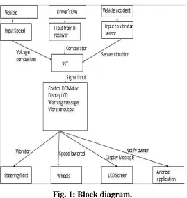
Fig. 1: Block diagram.
Drowsy driver detection system is divided into subsystems and these sub systems gives some
interconnected services. Architecture design can be defined as proving a framework for
sub-system control, in the first stage of the design process all subsub-systems of the drowsy driver
detection system are identified and hence, the design process output is a output of this a
explanation of the software architecture. A basic structural framework for a system can be
established through architectural design process. The identification of the major components
of the system and communications between these components is considered under this.
The system architecture below portrays the blocks required for the implemented system.
Figure 1 outlines the system architecture. The sensors need to detect respective parameters
and pass the signals to microcontroller. The outputs from SST are used as inputs by various
output devices to control the speed and display the message.
4.5 Input Module
This section is responsible for taking in crisp values of the vehicle, eye blink movements any
Gayathri et al. World Journal of Engineering Research and Technology
Purpose
The purpose of this module is obtaining values from each sensor and comparing them with
reference values.
Functionality
The functionality of this module is to obtain the raw values and pass signals to SST.
Input
The input to this module are the crisp values of vehicle speed, IR from eye blink sensor and
values from shock due to accident.
Output
The output of this module is fed into SST80C51 microcontroller.
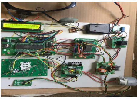
Fig. 2: Hardware setup 1.
4.6 SST Microcontroller
This section contains three inputs and outputs to various output devices. It receives the
signals from the previous modules
Purpose The purpose of this module is to pass the received values as input to output
devices.
Functionality This module provides inputs to the output devices.
Input The inputs would be outputs received by input devices.
Output The output of SST would be passed to other output devices so various
Gayathri et al. World Journal of Engineering Research and Technology
4.7 Output Devices
This section contains DC motor, LCD, vibrator, GSM module which perform their respective
function. The purpose of this module is to carry out respective functionalities such as slowing
down the vehicle speed, alertingthe driver, notifying the owner and displaying message on
the LCD.
4.8 Eye Blink Sensor
To observe the solidness of the traffic, we will be placing a few sets of IR transmitter &
receiver sensors on the side of the roads. On side IR transmitter device will be installed &
right opposite to the IR transmitter, an IR receiver will be positioned. This set of IR
transmitter & receiver will be placed at interim distance on the road.[19] The IR transmitters
are attached to supply, so that they will transmit high signal all the time. The IR receivers are
attached to the comparator circuit, to get digital signals. A low power operational amplifier
LM324 IC has been used to build a comparator circuit. Two set of LM324 IC has been used
in this project.[20]
5. RESULTS
5.1 The Drowsy Driver Detection System
The results obtained by running the module are as follows:
The owner‟s phone receives an audio warning message.
The owner can retrieve the location of the driver by choosing the ―location‖ option.
The owner can also get a list of driver‟s nearby police stations. With this, the photograph of the driver can be sent to owner‟s email address as specified in the clamped phone.
The wheel/motor is stopped as soon as an accident occurs, the vibrator in the eye blink
sensor frame vibrates and displays a message on the LCD.
When the driver falls asleep, the vibrator vibrates and the LCD displays the message.
Along with this, the vehicle speed is automatically reduced.
When the accelerometer is tilted randomly, that acts as the steering, a message is
displayed on the LCD the speed of the vehicle is reduced.
With all of the above mentioned, the android applications send and receives details
Gayathri et al. World Journal of Engineering Research and Technology
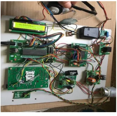
5.3 Eye is shut
Fig. 3: Hardware setup 2.
7. CONCLUSION
The proposed system helpful to avoid vehicle accidents because of driver‟s sleepiness using
eye and design the system for driver fatigue detection. If the driver becomes drowsy the eye blink sensor‟s frame vibrates attached to the vehicle and also the LCD displays the warning messages and it alerts the driver‟s through alarm sound to avoid the road accidents. The
wheel is slowed or stopped depending on the condition. This is accompanied by the owner being notified through the GSM module, so the owner can retrieve the driver‟s location,
photograph and a list of nearby police stations.
REFERENCES
1. MarcoJavier Flores, JoséMaría Armingol and Arturo de la Escalera, “Driver Drowsiness
Warning System Using Visual Information for Both Diurnal and Nocturnal Illumination Conditions‖”, Springer, EURASIP Journal on Advances in Signal Processing, 2010.
2. C.Nagarajan and M.Madheswaran, „Experimental verification and stability state space
analysis of CLL-T Series Parallel Resonant Converter with fuzzy controller‟ - Journal of
Electrical Engineering, 2012; 63(6): 365-372.
3. R.Raja and C.Nagarajan, “Performance Analysis of LCL-T Filter Based 2 Stage Single
Phase Gird Connected Module with ANN Controller using PV Panel," Current Signal
Transduction Therapy, 2018; 13(2): 159-167.
Gayathri et al. World Journal of Engineering Research and Technology
5. E.Geetha, C. Nagarajan, “Stochastic Rule Control Algorithm Based Enlistment of
Induction Motor Parameters Monitoring in IoT Applications," Wireless Personal
Communications, 2018; 102(4): 3629–3645.
6. M.Madheswaran, C.Nagarajan, “DSP Based Fuzzy Controller for Series Parallel Resonant converter”, Frontiers of Electrical and Electronic Engineering, 2012; 7(4):
438-446.
7. C.Nagarajan, “Single-Stage High-Frequency Resonantac/AC Converter Using Fuzzy Logic and Artificial Neural networks‟, Conference on Emerging Devices and Smart
Systems (ICEDSS), 2nd and 3rd March, organized by mahendra Engineering College,
Mallasamudram, 2018; 30-37.
8. E Geetha, C Nagarajan, “Induction Motor Fault Detection and Classification Using
Current Signature Analysis Technique”, Conference on Emerging Devices and Smart
Systems (ICEDSS), 2nd and 3rd March, organized by mahendra Engineering College,
Mallasamudram, 2018; 48-52.
9. GS SatheeshKumar, C Nagarajan, ST Selvi, “A Virtual Impedance Based Analysis of
Dynamic Stability in a Micro-Grid System”, Conference on Emerging Devices and Smart
Systems (ICEDSS), 2nd and 3rd March, organized by mahendra Engineering College,
Mallasamudram, 2018; 38-41.
10.CS Lakshmi, C Nagarajan, “Neural Controlled Multi-Level Inverter Based DVR for Power Quality Improvement”, Conference on Emerging Devices and Smart Systems
(ICEDSS), 2nd and 3rd March, organized by mahendra Engineering College,
Mallasamudram, 2018; 42-47.
11.S Thirunavukkarasu, C Nagarajan, “Performance Analysis of BLDC Motor Drive for Feed Drives”, Conference on Emerging Devices and Smart Systems (ICEDSS), 2nd and
3rd March, organized by mahendra Engineering College, Mallasamudram, 2018; 67-70.
12.JP Daniel, C Nagarajan, “Hybrid Filter for Distorted Voltage Source in Microgrids”,
Conference on Emerging Devices and Smart Systems (ICEDSS), 2nd and 3rd March,
organized by mahendra Engineering College, Mallasamudram, 2018; 11-15.
13.K Umadevi, C Nagarajan, “High Gain Ratio Boost-Fly Back DC-DC Converter using Capacitor Coupling”, Conference on Emerging Devices and Smart Systems (ICEDSS), 2nd
64-Gayathri et al. World Journal of Engineering Research and Technology
Space Analysis”, Iranian Journal of Electrical and Electronic Engineering, 2012; 8(3):
259-267.
15.C. Santhana Lakshmi and C. Nagarajan, “Multiconverter Technology Based Voltage
Compensation for Photovoltaic System” Ecology, Environment and Conservation, 2017;
23: 226-229.
16.C.Nagarajan and M.Madheswaran, ”Stability Analysis of Series Parallel Resonant Converter with Fuzzy Logic Controller Using State Space Techniques”, Electric Power
Components and Systems, 2011; 39(8): 780-793.
17.C.Nagarajan, M.Muruganandam and D.Ramasubramanian – „Analysis and Design of
CLL Resonant Converter for Solar Panel - Battery systems- International Journal of
Intelligent systems and Applications, 2013; 5(1): 52-58.
18.C.Nagarajan and M.Madheswaran, “Experimental Study and Comparative Analysis of
CLL-T and LCL-T Series Parallel Resonant Converter with Fuzzy/ PID Controller”,
Journal of Electrical Engineering, 2011; 11(3): 122-129.
19.C.Nagarajan and M.Madheswaran, “Analysis and Simulation of LCL Series Resonant Full Bridge Converter Using PWM Technique with Load Independent Operation” has been presented in ICTES‟08, a IEEE / IET International Conference organized by
M.G.R.University, Chennai, 2007; 1: 190-195.
20.C. Nagarajan, M.Madheswaran and D.Ramasubramanian, “Development of DSP based
Robust Control Method for General Resonant Converter Topologies using Transfer Function Model,” Acta Electrotechnica et Informatica Journal , 2013; 13(2): 18-31.
21.S.Sathish Kumar and C.Nagarajan, “Performance - Economic and Energy Loss analysis
of 80 KWp Grid Connected Roof Top Transformer less Photovoltaic power Plant,”