Xinhua et al. World Journal of Engineering Research and Technology
RESEARCH ON INDUSTRIAL ROBOT SERVO MOTOR
CONTROLLING SPEED SENSORLESS ALGORITHM
Dr. Xinhua Yan*, Xinxing Yan and Kezhi Zhang
Nobot Intelligent Equipment (Shandong) Co., Ltd., Liaocheng, China 252000.
Article Received on 30/07/2018 Article Revised on 20/08/2018 Article Accepted on 10/09/2018
ABSTRACT
Permanent magnet synchronous motor is the most commonly applied
motor for industrial robots. In this paper, the structure and working
principle of permanent magnet synchronous motor are analyzed, and
the mathematical model of permanent magnet synchronous motor in
different coordinate system is introduced based on coordinate
transformation. On this basis, the working principle of space voltage loss control algorithm
for three-phase voltage source inverter is introduced, and the model of permanent magnet
synchronous motor vector control system is set up. To realize the speed sensorless control of
permanent magnet synchronous motor, the model reference adaptive algorithm is used to
estimate the rotor speed and position, and the adaptive law is designed according to the
theory of wave's super stability. Since the slow convergence rate of the traditional model
referencing adaptive algorithm, the synovial state observer as an adjustable model is designed
in this paper, and the corrective feedback closed-loop link is added in the state equation,
which greatly improved the speed of the speed identification and realized the effective
estimation of the position and speed of the motor. Finally, the hardware in loop simulation of
the motor vector control is established by using MATLAB/Simulink. The simulation results
show that the sliding mode variable structure MRAS speed observer proposed in this paper
has good dynamic performance.
KEYWORDS: Permanent magnet synchronous motor; Vector control; MRAS sliding-mode; Dynamic speed estimator.
World Journal of Engineering Research and Technology
WJERT
www.wjert.org
SJIF Impact Factor: 5.218*Corresponding Author
Dr. Xinhua Yan
Nobot Intelligent
Equipment (Shandong) Co.,
Ltd., Liaocheng, China
1. INTRODUCTION
With the rapid development of electronic power technology and microelectronics, permanent
magnet synchronous motor has been widely used in different fields, such as agriculture,
automobile industry, electric power industry and so on.[1,2] Compared with the traditional electromotor, Permanent magnet synchronous motor (PMSM) has the advantages of less loss,
high efficiency and obvious power saving effect. Permanent magnet synchronous motor uses
permanent magnets to provide excitation, simplifies the structure of the motor, reduces the
cost of processing and assembly, and improves the reliability and efficiency of the motor
operation. Therefore, permanent magnet synchronous moto has been widely used. Because
the use of speed sensors will lead to increased cost, difficulty in installation, and low
reliability, researchers have studied how to avoid using speed sensors in applications. They
propose many control strategies for permanent magnet synchronous motor speed sensorless
vector control system. The reference model based on the stator flux vector and the MRAS
method of adjustable model are proposed in document.[3-5] The stator flux is calculated with voltage model and current model respectively. The adaptive algorithm is used to adjust the
stator flux of the two models, and then the motor speed is measured. The disadvantage of this
method is that the calculation is complex and the accuracy of the observer depends on the
accuracy of the motor parameters, especially in the voltage model. The stator resistance
varies with the temperature rise of the motor and has a great influence on the calculation
results of the stator flux. In document,[6,7] a model reference adaptive method based on stator current is given. This method is simple and has good performance in middle and high speed.
But the error of low speed running is large and the load is poor at less than 5% rated speed. It
is only suitable for some situations where low speed operation is not high. In document,[8] the high frequency injection method of using the motor salient effect is used. This method needs
to increase the extra bandpass filter, and the effect is obvious in the middle and low speed
domain. But as the speed increases, the frequency of the high frequency injection current and
the basic frequency current is getting closer and closer, and the resolution of the filter
decreases and the estimation effect becomes worse. In order to obtain a better control
algorithm, some researchers used the method of estimating the rotor position, including the
time computation, high dependence on the control chip, and the dynamic response is not
ideal. The sliding mode observer has the characteristics of fast response, insensitivity to
system internal parameter changes and external disturbances, and is simple and easy to
implement. However, this kind of sensorless detection method based on the back electric or
state observer is only suitable for high speed. At low speed, the position estimation precision
is reduced due to the inability to obtain enough phase voltage or back EMF. Therefore, in the
start-up stage of motor, a different position sensorless control strategy is needed.
In this paper, the model referencing adaptive principle is used to select the output of half back
EMF for the same physical meaning, and the speed and position signals are extracted by
adaptive control law. Under the above guidance, an adaptive variable structure sliding mode
observer for extended state of permanent magnet synchronous motor is proposed. The
extended state adaptive sliding mode observer is constructed with stator current and half
reverse potential. The adaptive speed adaptive law is proposed by using the equivalent semi
reverse EMF and the estimated semi reverse EMF model reference self-adaptive system. The
output of the adjustable model is close to the output of the reference model, thus the speed
signal and the half reverse EMF estimation signal of the permanent magnet synchronous
motor are extracted, and the system buffeting is weakened when the traditional sliding mode
observer is calculated to get the position and speed signal. According to Lyapunov's
improved pulse vibration high frequency injection method, it is based on the traditional pulse
vibration high frequency injection method. It simplifies the dynamic performance of the
motor at the low speed section and makes it easy to do in the process of current signal
processing. The model referencing adaptive law varies with the difference between the
reference model and the adjustable model. The rotor speed and position estimation can be
obtained by the adaptive law. Finally, the stability of the control method is proved under the
Popov super stability theory. Finally, a motor model based on variable structure sliding mode
observer and model referencing adaptive motor model is built, and the simulation analysis is
carried out.
2.Mathematical model of permanent magnet synchronous motor 2.1 Coordinate transformation of space vector
The coordinate transformation of space vector is an important mathematical method to
simplify the complex model of permanent magnet synchronous motor, and is the foundation
space vector mainly refers to the ABC transformation between three stationary coordinate
systems, αβ two stationary coordinate systems and d-q two rotating coordinate systems. The
motor stator currents in these three coordinate systems are shown in Figure 1.
(α)
β d
q b
ic ib
iβ
θ Φ
ω id
iq
ia iα
a
c
i
Figure 1: Stator current diagram in three coordinate systems.
It is shown that in the ABC three stationary coordinates, the ABC three axis angle difference
is 120 degrees, the stator three-phaseia, ibandiccurrent is equal in size, which is located on the
a, b, and c three axes respectively. The current vector is i, and the rotational speed of the
rotating magnetic field is . In the αβ two phase stationary coordinate system, the positive
direction of α axis coincides with the positive direction of an axis. The α axis lags behind the
β axis ninety electric angles in space, the current vector i and the α axis are positive angle of
φ, and the current component on the α and the β axis is i and i respectively. In the d-q two
phase rotating coordinate system, the direction of d axis is consistent with the direction of the
rotor flux, lagging behind the electric angle of the q axis at 90 degrees in space, and the
whole coordinate system rotates in space at the synchronous speed e, the angle of the
current vector i and the d axis is θ, and the components decomposed to the d-q axis are id and
q
i respectively. In order to realize the transformation between the three coordinate systems,
two coordinate transformation methods are needed, namely, the Clark transformation
between the three-phase stationary coordinate system and the two-phase stationary coordinate
system, and the Park transformation between the two-phase stationary coordinate system and
the two-phase synchronous rotating coordinate system. Clark transformation can be
= sin 30 sin 30 =0 bbcos 30 cccos 30i i i i
i i i
(1)
Form the form of a matrix
1 0.5 0.5
2 3 3 3 0 2 2 a b c i i i i i (2)
Clark inverse transform
1 0 2 3 = 0.5 3 2 3 0.5 2 a b c i i i i i (3)
From Figure 1, the Park transformation is introduced
= cos sin sin cos d
q
i i i
i i i
(4)
The form of a matrix is the form of a matrix
cos - sin
sin cos
d q
i i
i i
(5)
Park inverse transform array
cos - sin
sin cos d q i i i i
(6)
2.2 The mathematical model of permanent magnet synchronous motor
The mathematical model of permanent magnet synchronous motor is composed of stator
voltage equation, flux linkage equation, torque equation and mechanical motion equation.
Because permanent magnet synchronous motor is a nonlinear complex system, it is difficult
to establish a precise mathematical model.[15] Therefore, to simplify the model analysis process, we often neglect some parameters with less influence. Therefore, the following
assumptions are made before establishing the mathematical model of PMSM.[16]
(1) The stator armature winding produces sinusoidal induction electromotive force, and the
air gap magnetic field of the rotor permanent magnet is also distributed in the air gap
(2) The eddy current and hysteresis losses of stator and rotor cores are negligible;
(3) The saturation of the stator core is negligible and the inductance parameters remain
unchanged. And it is considered that the magnetic path is linear;
(4) Neglecting the damped windings of the rotor.
The voltage equation and flux linkage equation of motor stator winding are not constant
coefficient equations, but strong coupling time-varying equations. After decoupling the
motor, the voltage equation and flux linkage equation of the stator winding of the motor are
converted to solving the easier constant coefficient equation. The expression of the voltage
equation after its transformation:
q
d s d d d e q
q
q s q q q e q e f
u
R i
L
pi
L i
u
R i
L
pi
L i
(7)The udanduq denote the stator voltage in the d-q coordinate system in the equation;id and
q
i represent the stator current in the d-q coordinate system; L represents the equivalent
number of inductance in the d-q coordinate system;Rsrepresents the stator
resistance;erepresents the angular velocity of the motor rotor; the stator fluxsof the motor
is composed of the full flux linkagea,bandcin the static three phase ABC shaft system;
The rotor chainf consists of fa,fb, andfc. Its motor flux linkage equation:
=
s s+
s
L i
f
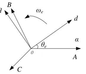
(8)For permanent magnet synchronous motor , the d axis of d-q two phase synchronous rotating
coordinate system coincides with the axis of rotor pole, and the q axis converse clockwise
forward d axis 90 electric angle, the angle of the axis of d axis and the stator winding of A
phase of motor is e, and rotate with the angular velocity e of the rotor in space. ABC three
phase stationary coordinate system and d-q two-phase synchronous rotating coordinate
A B
C
α
O
d
q ωe
θe
Figure 2: Three phase stationary coordinate system and two phase synchronous rotating coordinate system.
The flux linkage equation of PMSM in ABC three-phase stationary coordinate system is
decomposed into the flux linkage equation in d-q coordinate system.
=
+
=
f d d f
q q q
L i
L i
(9)wheref is the flux linkage between rotor permanent magnet and stator winding;LdandLqare
direct reactance and cross axis reactance;ia,ibandicare three-phase stator currents of
permanent magnet synchronous motor;a,bandcare three-phase stator flux linkage of
permanent magnet synchronous motor.
Electromagnetic torque equation of motor
e p d q q d
3
T =
n .(
.i -
.i )
2
(10)Combination Eq. 4 and Eq. 6
f
(
))
e p q d q q d
3
T =
n
i
L
L
.i .i )
2
(11)The equilibrium expression of the mechanical motion balance equation for three phase
permanent magnet synchronous motor is as follow
2 2
d d
D K
d d
r r
e L
r
J T T
t t
whereris the mechanical angle; theTLis the load torque; the J is the moment of inertia; the D
is the friction and the wind resistance torque coefficient which is proportional to the speed,
and the K is the torsion elastic torque coefficient.
In general, K can be approximately equal to zero, Load torque TL can be incorporated into the
frictional resistance moment, Thus, the dynamic equation of calculation is simpler, that is
d
n dt
e
e L
p J
T T
(13)
3. The principle and Realization of vector control
For the three-phase permanent magnet synchronous motor, the voltage, current, magnetic
potential and magnetic chain of the fixed rotor are rotated at the synchronous speed in space,
and their components on the three-phase stationary coordinate axis are all inflow, and it is
inconvenient to calculate, adjust and control them directly. And through vector control, the
stator three phase currentia,ibandicof the motor are transformed from three-phase stationary
coordinate system to DC currentidandiqof two phase rotating coordinate system. In this way,
the exchange physical quantities are transformed into DC physical quantities. It can be seen
from Eq. 10 that the excitation and flux linkage of the permanent magnet is determined by the
permanent magnet itself, and the inductance of the motor stator is also the parameter of the
motor itself. In this way, the torque componentiqand the excitation componentidof the stator
current determine the torque of the motor;idandiqare equivalent to the excitation current and
torque current in the DC motor. By controlling the two current ofidandiq, the permanent
magnet synchronous motor can be controlled like the DC motor.
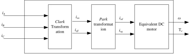
Clark Transform
ation iA
iB
iC
Park transformat
ion isα
isβ
isd
isq
ω
Te Equivalent DC
motor
In the Eq.9, if id=0, the stator current vector is, only q axis component, no d axis component.
There is an electromagnetic torque equation.
f. ( ))
e p q d q q d
3
T = n . i L L .i .i
2
(14)It can be seen from the formula that the alternating and direct axis currents in the torque
expressions are completely decoupled, and because of the permanent magnet rotor, f is a
constant value. Therefore, the electromagnetic torque is proportional to the q axis component
q
i of the stator current and can achieve the same control effect as DC motor. At this point, the
torque to current ratio is the largest, and the minimum stator current can be used to generate
the required torque. Moreover, due to the decrease of stator current, copper consumption is
reduced and motor efficiency is improved. As shown in Figure 4,the block diagram of
vector control system using id=0 control mode is presented. The whole control system mainly
includes permanent magnet synchronous motor, PI controller module, Park inverter module,
voltage space vector pulse width modulation module (SVPWM), three-phase full bridge
inverter circuit, stator current acquisition module, rotor position acquisition module, Clark
transform module, Park transform module, and flux observer module.
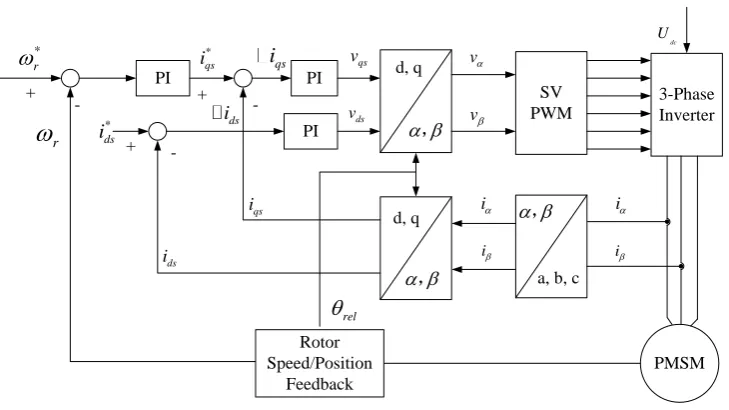
PI PI d, q
SV PWM 3-Phase Inverter PMSM d, q
a, b, c * r + + PI * ds i + - , , , Rotor Speed/Position Feedback * qs i r -qs i -ds i qs i ds i ds v qs v i i i i rel v v dc U
Figure 4: Vector control diagram of permanent magnet synchronous motor.
The vector control system is divided into two negative feedback loops, the outer ring is the
speed loop, which ensures the actual speed of the motor to track the given speed steadily, and
the inner ring is the current loop, which ensures the fast and stable current of the motor to
The stator currentia,ibandicunder the three-phase stationary coordinate system collected by
the current sense sensor are transformed intoidandiqin the αβ two phase stationary coordinate
system by Clark. Becauseidandiqare DC components, the permanent magnet synchronous
motor can be controlled by controlling these two currents. The difference betweenid andiqare
the corresponding expected excitation currentid
and torque currentiq
are the input of the
current PI controller. The PI controller outputs the desired d axis control voltageudand the
desired q axis control voltageuq, and then through inverse Park transform, the α axis
componentuand β axis componentuof the stator voltage in the αβ biphasic stationary
coordinate system are obtained;uanduare modulated by SVPWM module and output six
PWM waves. It is used to control six switch tubes in the three-phase full bridge inverter
circuit, and output the three-phase AC voltage to the permanent magnet synchronous motor
and complete the inner loop current control. For the speed outer loop, as shown in Figure 4,
the desired torque currentiq
required for the current inner loop control is given by the PI
speed controller in the speed outer loop control. The input speed of the PI speed controller is
the difference between the expected speedm
and the mechanical speedm. The mechanical
speedmis calculated by collecting the rotor position information of the speed sensor. In the
block diagram above, the θ parameters of the Park transform and the Park inverse transform
module are obtained by integrating the actual speed of the flux observer module.
4. Speed sensorless technology
In the modern AC speed regulation system, in order to get high performance speed control,
speed closed-loop control is adopted, and speed sensors must be installed on the motor shaft.
But in practical systems, the installation of speed sensors is often limited. The main problems
are the following problems.
(1) The installation of speed sensor reduces the robustness and simplicity of the system.
(2) High precision speed sensors generally cost more and increase system costs.
(3) In some harsh conditions, such as high temperature, humidity, etc., the installation of
speed sensors will reduce the reliability of the system.
(4) There are some difficulties in the installation of speed sensors. If they are not installed
In order to avoid these problems, people turn to study speed identification methods without
speed sensors. In recent years, this research has become a hot issue in AC drive. Foreign
studies began in 1970s. For the first time, the application of speed sensorless to vector control
was completed in 1983 by R. Joetten, which made the development of AC drive technology a
new step. In the following ten years, scholars at home and abroad have done a lot of work in
this field, and so far, many methods have been put forward. In general, these methods can be
divided into the following: ①Dynamic speed estimator; ②Model reference adaptive
(MRAS); ③Based on PI regulator method; ④Adaptive speed observer; ⑤Rotor tooth
harmonic method; ⑥High frequency injection method; ⑦A method based on artificial
neural network. In a variety of different methods, model reference adaptive system is the
most popular technique. If the speed deduction is attributed to reference identification, the
model reference adaptive theory (MRAS) can be used to construct a system that can identify
speed. In this case, the system is a nonlinear system, so the super stability theory of Popov
can be used to deduce the identification algorithm under the condition of ensuring the
stability of the system.
In all kinds of observers, sliding mode variable structure is not very demanding for the
precision of the mathematical model of the system. It is not sensitive to the change of the
system parameters and the disturbance of the external disturbance, and the control method is
simple and easy to be realized. It gets the universal attention of the scholars at home and
abroad and has been widely used in the field of electric drive. But because the uncertain
factors such as variable structure control meet the "matching condition", that is, "matching
condition", that is, it has the robustness against external interference and internal parameter
perturbation, but it is difficult to determine the upper and lower bounds of the change of the
uncertain parameters in practice. Therefore, the boundary of uncertain factors can be
estimated in real time by using the adaptability of MRAS to the change of system parameters,
and a variable structure MRAS speed identification algorithm is proposed. In this method, the
variable structure control has the robustness against external interference and internal
parameter perturbations and the adaptability of MRAS to the change of system parameters.
This method can achieve accurate and rapid tracking of the reference model, meet the
requirements of the system steady-state error, improve the accuracy of the magnetic chain
4.1 Construction of state error equation
According to the voltage equation flux linkage equation of AC induction motor in two-phases
stationary αβ coordinate system, the rotor flux linkage voltage model under two-phases
stationary αβ coordinates is established.
=
= r
ra s s s s s
m
r
r s s s s s
m
L
u R i dt L i
L
L
u R i dt L i
L
(15)According to the state equation of AC induction motor in two phase stationary αβ coordinate
system, the rotor flux linkage current model in two phase stationary αβ coordinate system can
be obtained.
d dt
ra ra s
r
r r s
i A b i
(16)
where 1 1 r r r T A T
, m
r
L b
T
.
As the rotor speed information is included in the current model, the model is selected as an
adjustable model, and the rotor flux voltage model is employed as a reference model, and Eq.
16 is simplified
d
dtr Arrabis (17)
The rotor flux estimation model with adjustable parameters is constructed.
ˆ ˆ
d ˆ
ˆ ˆ
dt
r r s
r s r r i A b i
(18)
where 1 ˆ ˆ 1 ˆ r r r T A T , ˆ r
and ˆ
r
The Eq.19 is simply written as
d ˆ ˆ ˆ =
dtr Ar r bis (19)
Definition of error state
ˆ = r
e r
(20)
The error equation of Eq.19 subtraction Eq. 20.
d ˆ ˆ
= ( )
dte Ar r r (21)
4.2 Switching function construction
The principle of selecting switching surfaces is that s(e) =0 occurs when the system slips, and
the sliding motion is asymptotically stable and has better dynamic quality. According to this
principle, the switching functions of the variable structure MRAS speed identifier constructed
are as follows.
ˆ ˆ
= r r r r
s (22)
4.3 Determination of the equivalent velocity
According to the basic idea of variable structure control, if the system enters sliding mode
control, then S=0. The expression of the equivalent velocity is as follows
m ( ˆ ) m (ˆ )
ˆ ˆ
sa r r s r r
eq
r r r r r
L i L i
T
( ) (23)
This formula shows that when the estimated flux is convergent to the reference flux, the
equivalent velocity converges to the real velocity.
4.4 Design of sliding mode observer
According to the obtained switching function and equivalent speed, the speed observer can be
designed. When the constant switching control method is adopted, the speed estimation
expression is as follows:
ˆ= sgn( )
M
s
(24)is the equivalent velocity. In order to weaken the buffeting, the filter method is used. The
low-pass filter is used to smooth the control signal and weaken chattering effectively.
5. Build a simulation model 5.1 Build a motor model
According to the voltage equation of the permanent magnet synchronous motor in the d-q
shafting, the motor model in two phase stationary coordinate system is built as follows.
Figure 5: Motor model.
5.2 Construction of vector control system
According to the principle of vector controller, the following vector control system is built.
Speed PI control module:
Figure 6 Speed PI control module.
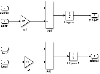
5.3 Construction of sliding mode observer module
Figure 7: Current estimation module.
6. Simulation results and comparison
In the estimation formula of rotor speed, the selection of M value has a great influence on the
performance of the speed regulating system. Generally speaking, the larger the M value is
chosen, the better the control of sliding mode variable structure is, but at the same time, it
will bring more obvious buffeting phenomenon. When the M value is reduced, the chattering
phenomenon is obviously improved, but if the M value is too small, the speed regulation
system cannot work normally.
Figure 8 is the speed and flux linkage curve when the speed is abrupt. The horizontal axis is
in seconds, and the vertical axis is rpm. The given load is 10 N/m, and the given speed is
1200 rpm. It can be seen from the diagram that the rotational speed of the measurement
module is smooth and the tracking performance is good in the steady state. The calculated
speed is swinging back and forth along the sliding surface in a small range, and the difference
is very small. It shows that the speed estimation method can reflect the rotor speed of the
motor in time. After 0.5 seconds, the motor will reenter the steady state and have no
overshoot. It shows that this speed regulation method has better dynamic performance and
can meet the general engineering requirements, but there is a certain speed fluctuation
Figure 8: Speed and magnetic chain curve when the speed is abrupt.
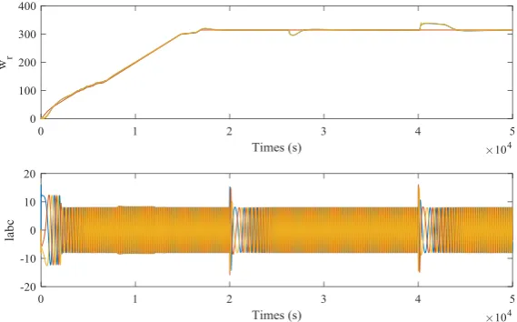
Figure 9 shows the change of state when the motor runs steadily at 1.5R; rated load at 300
r/min. When the load is suddenly increased, the running speed of the motor drops to 50 r/min,
and the torque drops rapidly. After the motor running speed begins to recover from the lowest
point, the output torque is basically stable. When the load is added to the motor, the speed of
the motor is restored to the stable running value. The time is about 0.5s. It can be seen from
the actual speed wave and current waveform that the motor runs very stable with the rated
load of 1.5 times. The experiment shows that when the given speed is 300 r/min, the motor
has good stability and strong carrying capacity.
0 1 2 3 4 5 -30
-20 -10 0 10
Times
Te
0 1 2 3 4 5 0
100 200 300 400
Times
W
_r
(a) Torque with time (b) Speed with time Figure 9: Speed and curve of torque mutation.
7. CONCLUSION
The simulation results show that the speed sensorless control method of permanent magnet
synchronous motor based on the estimated current model has a fast speed estimation of rotor
rotor position are estimated based on the error correction between the measured current value
and the estimated current value. It starts directly in the static state of the motor, has no state
switching, has the fast starting ability, the high speed state runs well, and the low speed
running capacity is improved significantly compared with the existing methods. The
proposed algorithm is very easy to be realized through DSP, and has strong robustness to the
uncertainty of motor parameters in the operation. It has the advantages of low cost, high
reliability, good stability and wide range of use.
ACKNOWLEDGEMENT
This paper is funded by the Key Research and Development Plan Project of Shandong
Province (NO: 2016ZDJS02A02).
REFERENCE
1. Walambe R A, Joshi V A. Closed Loop Stability of a PMSM-EKF Controller-Observer
Structure [J]. IFAC-PapersOnLine, 2018; 51(1): 249-254.
2. Chen S Y, Luo Y, Pi Y G. Pmsm sensorless control with separate control strategies and
smooth switch from low speed to high speed. ISA transactions, 2015; 58: 650-658.
3. Ohara M, Noguchi T. Rotor position sensorless control and its parameter sensitivity of
permanent magnet motor based on model reference adaptive system. IEEJ Transactions
on Industry Applications, 2012; 132: 426-436.
4. Khlaief A, Boussak M, Chaari A. A MRAS-based stator resistance and speed estimation
for sensorless vector controlled IPMSM drive. Electric Power Systems Research, 2014;
108: 1-15.
5. Gao W, Guo Z. Speed sensorless control of PMSM using model reference adaptive
system and RBFN[J]. Journal of networks, 2013; 8(1): 213.
6. She Zhiting, Yuan Junbo, Zheng Yong, et al. Interactive model reference adaptive PMSM
speed identification. Electrical transmission, 2011; 41(3):3-7.
7. Hu Weizhen, Wang Yue, Li Mingxi, et al. Research on speed sensorless control strategy
of multiphase permanent magnet direct drive wind power generation system based on
MRAS. Power System Protection and Control, 2014; 23: 118-124.
8. Deng Xianming, Wang Wenwen, Pang Qingqing. Sensorless Position Detection of
Permanent Magnet Synchronous Motor. Laboratory Research and Exploration, 2015;
9. Genduso F, Miceli R, Rando C, et al. Back EMF Sensorless-Control Algorithm for
High-Dynamic Performance PMSM. IEEE Transactions on Industrial Electronics, 2010; 57(6):
2092-2100.
10.Lee G B, Park J S, Lee S H, et al. High-performance sensorless control of PMSM using
back-EMF and reactive power. Iccas-Sice. IEEE, 2009; 407-411.
11.Yin Zhong-gang, Liu Jing, Zhong Yanru, et al. Low-speed performance of speed
sensorless vector control for induction motor based on two-parameter model reference
adaptive. Transactions of China Electrotechnical Society, 2012; 27(7): 124-130.
12.Xing Yan. Research on Key Technologies of High Performance Torque Control for
Permanent Magnet Synchronous Motor. Northeastern University, 2014.
13.Lu Wenqi, Huang Wenxin, Hu Yuwen. Sensorless control of a novel sliding mode
observer for permanent magnet synchronous motors. Control Theory and Applications,
2009; 26(4): 429-432.
14.Yuan Anbei. Research on Sensorless Control Technology of Permanent Magnet
Synchronous Motor. Nanjing University of Science and Technology, 2014.
15.Du Lijuan, Zhang Xiaoyu. Analysis of Extended Mathematical Model of Permanent
Magnet Synchronous Motor. Journal of North China University of Science and
Technology, 2016.
16.Huang Chenrong, XU Bo. Simulation Analysis of Vector Control of Permanent Magnet
Synchronous Motor. Electric Automation, 2016; 38(2): 11-12.
17.Xu Xinyi. Exploration of PMSM Speed Sensor Based on Extended Synovial Controller.
Electronic Test, 2015; 05: 4-6.
18.Gao Zheng. Design and Implementation of PMSM Synovial Observer Based on DSP.