Design and analysis of ICE bar shaped patch
antenna parameters using HFSS
BASHEER ALI SHEIK
1, K L V PRASAD2, G A ARUN KUMAR3
Abstract-- A Microstrip antenna with an ice cream bar shaped patch is designed at a frequency of 2.4GHz. This antenna is designed using an FR4 epoxy substrate material (Ɛr = 4.4) is simulated for different slot positions
on the substrate using HFSS software and achieved a return loss of 30.7 dB. These antennas will find vast applications in Wireless LAN’s and WiFi.
Index Terms-Microstrip patch antenna, HFSS software, WLAN
I. INTRODUCTION
A Microstrip patch antenna is a narrowband, wide‐beam antenna fabricated by etching the antenna element pattern in metal trace bonded to an insulating dielectric substrate, such as a printed circuit board, with a continuous metal layer bonded to the opposite side of the substrate which forms a ground plane. Low dielectric constant substrates are generally preferred for maximum radiation. The conducting patch can take any shape but rectangular and circular configurations are the most commonly used configurations. Other configurations are complex to analyze and require heavy numerical computations. A Microstrip antenna is characterized by its Length, Width, Input impedance, polarization, and Gain and radiation patterns.
Microstrip patch antennas are increasing in popularity for use in wireless applications due to their low profile structure. Therefore they are extremely compatible for embedded antennas in handheld
wireless devices such as cellular phones. The telemetry and communication antennas on missiles need to be thin and conformal and are often in the form of Microstrip patch antennas. Another area where they have been used successfully is in Satellite communication. Some of the major advantages are
Light weight and low volume. Low profile planar configuration which can be easily made conformal to host surface.
Low fabrication cost.
Supports both linear as well as circular polarization.
Mechanically robust.
II. GEOMETRY:
The geometry is based on the calculations of width, height and thickness etc. by mathematical analysis. Patch dimensions --- (1) L -2 --- (2) --- (3) --- (4) Ground Dimensions Wg=6H+W--- (5)
Lg=6H+L--- (6)
III. SOFTWARE USED
HFSS is a commercial finite element method solver for electromagnetic structures from Ansys .The acronym originally stood for high frequency structural simulator .It is one of several commercial tools used for antenna design , and the design of complex RF electronic circuit elements including filters, transmission lines and packaging. HFSS is a high performance full wave electromagnetic (EM) field simulator for arbitrary 3D volumetric passive device modeling that takes advantage of the familiar Microsoft Windows graphical user interface. It integrates simulation, visualization, solid modeling, and automation in an easy to learn environment where solutions to your 3D EM problems are quickly and accurate obtained. Ansoft HFSS employs the Finite Element Method (FEM), adaptive meshing, and brilliant graphics to give you unparalleled performance and insight to all of your 3D EM problems. Ansoft HFSS can be used to calculate parameters such as S-Parameters, Resonant Frequency, and Fields. Typical uses include:
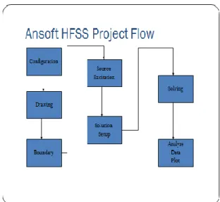
Fig1: ANsoft HFSS Project Flow.
IV. ANTENNA DESIGN
The ice bar shaped patch antenna design requires three elements ground, substrate and patch. In this design FR4 epoxy material has been used for substrate having 4.4 as its dielectric constant value. The substrate is having the dimensions of 36.6mm x
65.1mm x 1.6 mm. The ice bar shaped patch is
placed on the substrate with proper geometry. The design of this Microstrip antenna can be seen from figure 1 below. This design is simulated using HFSS at 2.4 GHz frequency for return loss and radiation pattern. The results can be observed from the following figures. From this design we achieved a return loss of 20.1 dB.
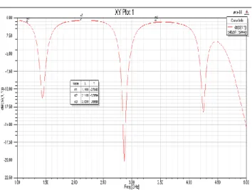
To further improve the return loss of antenna the above said design is modified by introducing a narrow rectangular slit on the patch antenna. The performance of the antenna can be assessed by placing the narrow rectangular slit at different locations on the patch. There is necessity in doing this change in geometry of the slot for improving the return loss. By placing the narrow rectangular slit at two different positions (top & bottom) and fed with a coaxial cable. By simulating this design with HFSS we achieved a return loss of 12.2 dB & 30.7 Db. The design and the results can be observed from the following figures.
Fig 3: Design of patch with slit on top
Fig 4: Design of patch with slit at bottom
V. RESULTS & DISCUSSION
Fig 5: S11 vs. Frequency plot of Patch without slit.
Fig 6: S11 vs. Frequency plot of Patch with slit on top
Fig 7: S11 vs. Frequency plot of Patch with slit at
bottom.
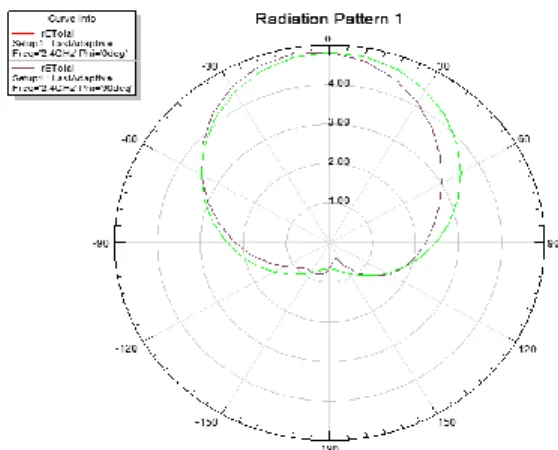
Fig 9: Radiation pattern for theta = 00 and 900 of Patch with slit on top.
Figure 9 Radiation pattern for theta = 00 and 900 Patch with slit at bottom.
Table 1: VI. Result Analysis
Note: Everything is measured on the bases of 10dB above.
VI. CONCLUSION
The ice bar shaped Microstrip patch antenna at 2.4 GHz is designed with and without narrow rectangular slit in HFSS software achieved a return loss of 30.7 dB. This patch antenna is simulated over range of frequencies from 1 to 5GHz. This antenna cannot be confined only to single frequency since it shows resonance at three different frequencies it can be used as Triple band frequency antenna. These antennas find application in WIFI & Wireless LAN’s.
REFERNCES
[1] K. Phaninder Vinay, Basheer Ali Sheik, A. Trinadha Rao “Design and analysis of slot antenna parameters using HFSS” IJITEE, ISSN: 2278-3075, Volume-3, Issue-12, May 2014
[2] D. Pozar and D. Schaubert, “Scan blindness in infinite phased arrays of printed dipoles,” IEEE Trans. Antennas Propag., vol. AP-32, no. 6,pp. 602– 610, Jun. 1984.
[3] S. Zavosh, “Analysis of circular microstrip patch antennas backed by circular cavities,” Department of Electrical, Computer and Energy Engineering, ASU, Tempe, AZ, USA, 1993.
[4] D. Sievenpiper, “High-impedance electromagnetic surfaces,” Department of Electrical Engineering, UCLA, Los Angeles, CA, USA, 1999. [5] H. Boutayeb, T. Djerafi, and K. Wu, “Gain enhancement of a circularly polarizedmicrostrip patch antenna surrounded by a circular mushroom-like substrate,” in Proc. EuMC, Sep. 2010, pp. 257– 260.
[6] H. Boutayeb, T. A. Denidni, K. Mahdjoubi, A.-C.Tarot, A.-R.Sebak, and L. Talbi, “Analysis and design of a cylindrical EBG-based directive antenna,” IEEE Trans. Antennas Propag., vol. 54, no. 1, pp. 211–219,
2006.
[7] J. Bell and M. Iskander, “Effective propagation properties of an enhanced hybrid EBG/ferrite ground plane,” IEEE Antennas Wireless Propag.Lett., vol. 7, pp. 74–77, 2008.
[8] J. Bell and M. Iskander, “Equivalent circuit model of an ultrawideband hybrid EBG/ferrite structure,” IEEE Antennas Wireless Propag. Lett., vol. 7, pp. 573–576, 2008.
[9] Y. Liu, C. G. Christodoulou, P. F.Wahid, andN. E. Buris, “Analysis of frequency selective surfaces with ferrite substrates,” in Proc. Antennas
Propagation Soc. Int. Symp., Jun. 1995, vol. 3, pp. 1640–1643.
[10] L. Greetis and E. Rothwell, “A self-structuring patch antenna,” in Proc. IEEE Antennas Propag. Soc. Int. Symp., Jul. 2008, pp. 1–4.
[11] C. A. Balanis, Advanced Engineering Electromagnetics, 2nd ed. New York, NY, USA: Wiley, 2012.
[12] C. A. Balanis, Antenna Theory: Analysis and Design, 3rd ed. New York, NY, USA: Wiley, 2005.
Basheer Ali Sheik1 is presently working as an Assistant Professor of ECE Department in prestigious Aditya college of Engineering & technology,AP,India He obtained M.Tech from AU College of Engineering. B.Tech from SRKR Engineering College.
KLV Prasad2 is presently working as an Assistant Professor of
ECE Department in prestigious Aditya college of Engineering& technology,AP,India He obtained M.Tech from GITAM, Visakhapatnam.B.Tech from Pragathi Engineering College.
G A Arun Kumar3 is presently working as an Assistant Professor
of ECE Department in prestigious Aditya college of Engineering& technology,AP,India He obtained M.Tech from B V C Engineering College.B.Tech from Aditya Engineering College.