Surface Modification of Gamma-Titanium Aluminides
with L1
2-Type Tri-Aluminides by Pack Cementation
Takashi Kimura
1;*, Tohru Awane
1, Ke Wai Gao
2, Lijie Qiao
2and Kenki Hashimoto
31
National Institute for Materials Science, 305-0047, Tukubashi, Japan 2University of Science and Technology Beijing, 100008, Beijing, P. R. China 3Japan Society for Promotion of Science, 110-03, Tokyo, Japan
The surface of an L10-type TiAl base alloy has been modified by coating it with an L12-phase (AlMn)3Ti(V) using a pack-cementation
method in a temperature range of 1273–1473 K and with a treatment time of 18–72 ks. The structural morphology and composition distribution in the coat and substrate were analyzed by EPMA and XRD to examine the factors that control the thickness of the coat. Two-phase equilibrium was confirmed between the L10-phase substrate and the L12-phase coat at each temperature tested. Aluminum particulates, 1–2mmin diameter,
were observed inside the coat and were confirmed to be related to the experimental condition and to the increase in coat thickness. The coat is 35mmthick at temperature range of 1373–1473 K, while at the temperature range of 1273–1323 K the thickness is 11–12mm. The temperature dependence of coating layer is different from that was reported previously. The results are then discussed from facts basically revealed in this experiment and/or based on information about the phase equilibrium between L10and L12.
(Received August 19, 2004; Accepted February 28, 2005; Published April 15, 2005)
Keywords: Intermetallics, gamma-titanium aluminide, titanium trialuminide, Surface modification
1. Introduction
A number of fundamental and developmental studies have been conducted on an intermetallic compound of L10-type
gamma-TiAl base alloy as a lightweight, heat-resistant material because of its superior specific tensile strength and creep strength at high temperatures. In one successful result, poor ductility of the alloy at room temperature increased up to 2% elongation by the addition of a third element.1–4)
Meanwhile, with this alloy’s feature of oxidation resistance rapidly decreasing at temperatures exceeding 1173 K, a certain level of improvement has been achieved by applying various methods and processes, such as: low-oxygen thermal treatment methods,5) sulfidation processes,6)physical vapor
deposition processes7,8) pack cementation (PC) processes,9)
and aluminum diffusion penetration process.10)A successful
improvement has been reported recently on the alloy’s heat resistance at 1273 K, in which a PC coat is applied using an L12-type compound (AlCr)3Ti.11)In dealing with coating by
compounds, however, the relevant mechanisms have yet to be clarified. These mechanisms, which include factors in the composition and thickness control of the coating, must be studied.
The authors have so far developed (AlMn)3Ti, an L12-type
compound that has an elongation of 1.5% at room temper-ature.12)The oxidation resistance of the compound has been
proven superior to that of TiAl even at 1273 K,13)reasonably
demonstrating that the compound is one of the major candidates for a PC coating material to improve the oxidation resistance of TiAl. On the other hand, a diffusion couple test has been performed on a pair of L12-type (AlMn)3Ti
(1 mol%V) phase and L10-type TiAl (1 mol%Mn, 1 mol%V)
alloys. The results clearly showed the establishment of two-phase equilibrium in the range of 1273–1473 K.14)
In the present study, the structural morphology and composition distribution of the coating layer of the L12
-phase (AlMn)3Ti(V) and of the substrate of the L10-type TiAl
base alloy are examined in relation to their dependence on PC treatment temperature and time. The results confirmed a two-phase equilibrium between the substrate of the L12-phase and
the coating layer of the L10-phase. However, aluminum
particulates, 1–2mmin size, were observed inside the coat, distributed in a straight line almost parallel to the interface between the coat and the substrate. The composition of the surface layer was nearly the same as that of the alloy powder used for the PC treatment. The thickness of the coating layer depended on the PC treatment temperature and time. The results are then discussed in relation to facts basically revealed in this experiment and/or in relation to information on the phase equilibrium between the L10and L12 phases.
2. Experimental Method
The material Ti–49%Al–1%Mn–0.9%V (mol%) was employed as a substrate, while Ti–59.4%Al–12.2%Mn– 1.0%V served as the coating material for the PC treatment. Let the former be referred to as the L10-phase alloy and the
latter as the L12-phase alloy. The L10-phase alloy was
heat-treated at 1473 K for 86.4 ks, after which a columnar specimen of 8mm5mm3mm was prepared using EDM. The specimen then received final polishing with #1000 emery paper. The L12-phase alloy was homogenized
at 1273 K for 172.8 ks and then was mechanically crushed into particles with diameters of 0.3 mm or less. The particulate material was ground using an alumina mortar. The PC treatment employed powders with diameters in the range of 74–107mm, as well as powders with diameters of 45mm or less. The former was used as the main powder, while the latter served as the getter. As part of the experiment, L12-phase alloy also was tested as a substrate.
A high-purity alumina crucible (30mm and 30 mm high) was used as a container and filled with the main powder, plus -Al2O3 added as an inhibitor by 10 mass%. The columnar
specimen was mounted in the main powder and topped with *Corresponding author, E-mail: [email protected]
an approximately 2 mm thick layer of the getter powder. Then a stainless-steel disk weighing about 12 grams was inserted as the applied load. The alumina crucible was wrapped entirely with Ta foil (0.2 mm thick) and inserted into a transparent silica tube (56mm and 1700 mm long). The PC treatment was performed through the use of a horizontal-type electric furnace (heating head length of 500 mm, soaking zone length of 40 mm). After the PC treatment was over, the crucible was moved away from the heating furnace by sliding the silica tube. The vacuum gauge, located at the lower pressure side of a diffusion pump, was used to confirm the PC process pressure. The PC treatment was performed once the pressure reached the order of 104Pa while the
lower-pressure side of the diffusion pump was connected to a PC processing chamber by a rubber tube (1 m in length, 9mm in inner diameter).
A JEOL 3500ER diffractometer was employed for X-ray diffraction of the surface material of the PC coating. A diamond abradant was used for the final polishing of the cross sections produced by binary division. A HITACHI 3100HT SEM (scanning electron microscope) was used for observa-tion and EPMA (electron probe microanalyser) analysis was done by a JEOL JXA-8900RL electron microprobe.
3. Experimental Results
3.1 X-ray diffraction of PC coating material
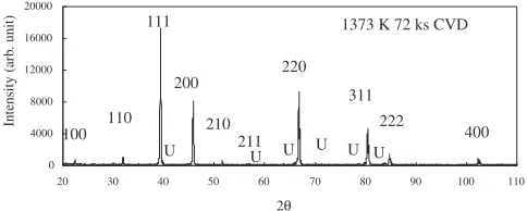
Figure 1 show X-ray diffraction patterns obtained from the surface of a specimen taken after a PC treatment at 1373 K for 36 ks. The clear diffraction lines were indexed as being from the L12-type crystal lattice. The ratio of diffraction line
intensity I(100) to diffraction intensity I(110) is less than one. Likewise, the ratio I(200)/I(220) is less than unity, showing a difference from powder samples of the L12-phase alloy,
whose intensity ratios exceeded unity. However, in the group of diffraction lines indexed as being from the L12-type crystal
lattice, the maximum and minimum diffraction intensities were observed at (111) and (400), respectively. It also was observed that the pair of I(100) and I(110) was smaller than the pair of I(200) and I(220). These characteristics are quite similar to those of the diffraction pattern of the powder specimen. These facts indicate that diffraction patterns could be obtained that closely resembles not only the angle of the diffraction lines but also intensity distribution of diffraction patterns from powder samples. Thus it is reasonably concluded that the surface material of the PC coating is composed of fine grain crystal with slightly preferred orientation compared to the powder samples.
Meanwhile, in Fig. 1, five more extremely weak diffrac-tion lines are observed. Of them, three were identified as diffraction lines from Al2O3, while the remaining two
differed from the diffraction lines of both the L10-type
crystal lattice belonging to the substrate and the DO19-type
crystal lattice, the Ti3Al phase, a slight amount of which is
contained in the substrate.
A PC treatment was conducted at 1373 K for 36 ks on the L12-type phase alloy as a substrate. The alloy’s X-ray
diffraction pattern exhibited a strong preferred crystal orientation; the intensity distribution of corresponding diffraction lines differed from the diffraction patterns of the powder samples.
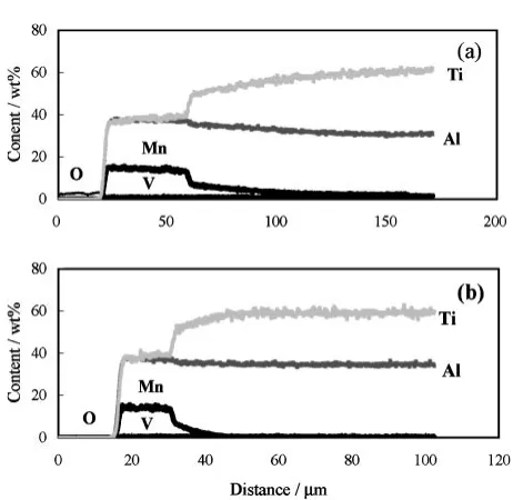
3.2 Cross sections of specimens after PC treatment Results of EPMA analysis for cross section of specimens are shown in Fig. 2(a)–(b) and (c), the former corresponding to a PC treatment at 1423 K for 72 ks, while the latter corresponded to that at 1323 K for 72 ks. BEI designates a composition image formed by back-scattering electrons, while Al-K, V-K, Mn-K, O-K, and Ti-Krefer to the respective X-ray images obtained by using characteristic K rays of the alloy elements. The X-ray images of Mn-Kand Ti-Kmost clearly demonstrate compositional changes, and the image of O-Kexhibits an oxide phase. The upper side of each texture corresponds to the surface of the respective specimen, while the lower side refers to the substrate. Changes in composition do not appear clearly on BEI, so that it is impossible to recognize an interface between the coat and the substrate. A color gauge was placed between (a) and (b) to measure concentrations; red on X-ray images mean high concentrations of respective elements, and darkening color indicates lower concentration. The Ti-K images in Fig. 2(b) and (c) show interfaces dividing the green zone on the surface of the specimen and the yellow zone on the flame inside the specimen. Furthermore, the Mn-Kimage shows that both zones are divided by the same kind of interfaces; one representing a high Mn content and the other corre-sponding to an extremely low concentration of Mn. From a comparison between the results of X-ray diffraction and the alloy composition, it can be estimated that the zone with high Mn and low Ti concentrations represents the L12-type phase
as a coat, while the zone inside the specimen with low Mn and high Ti concentrations corresponds to the substrate of the L10-type phase. These interfaces look like small waves with
sharp kinks in the PC coating material at 1323 K, whereas those at 1423 K show broad waves but quite smoothly curved interface lines.
Inside the coat, on the other hand, lines of particulate materials are observed nearly parallel to the surface of the specimens. On the spots where the particulate materials are found, the Al-Kand O-Kimages contrast starkly with the Ti-Kimage; the former both show red while the latter shows purple. These colors correspond to a high concentration of Al and oxygen, on the other, a minute concentration of Ti, respectively. The particulate materials were presumed to be an aluminum oxide. Further analysis of the results of the X-ray diffraction led us to conclude that the particulate material is alumina.
By comparing the PC processing at (a)–(b) 1423 K with 0
4000 8000 12000 16000 20000
20 30 40 50 60 70 80 90 100 110
2θ
Intensity (arb
. unit)
1373 K 72 ks CVD
220
400 222
311
210 200 111
110
100 211
U
U U
U U U
[image:2.595.48.290.668.765.2]that at (c) 1323 K, we found that the former brought about both a thicker coat and larger alumina particles.
Analysis of the representative lines of the coat and substrate on the PC-treated specimens are shown in Fig. 3(a) and (b). The region with high Mn content and the region with high Ti content correspond to the coat and the substrate, respectively.
[image:3.595.120.478.72.454.2]A composition change in the substrate of the 1373 K PC-treated specimen is observable at a longer distance than that of the 1323 K specimen. At the interface between the substrate and the coat, the transition of Ti content from the substrate to the coat is slightly higher in the profile of the 1323 K PC-treated specimen, (b) than those in the 1373 K specimen, (a). In the coat, Mn and Al contents decrease and Ti content increases, while in the substrate region from the interface to the inner substrate, the features of each content show the reverse trend. Thus, the line analysis showed several variations in the composition distribution, depending on the PC treatment temperature.
Table 1 shows changes in the average thicknesses of coats, in the average distance between an alumina particle and the interface, and in the average diameter of alumina particles in relation to changes in PC treatment times and temperatures. The thickness, (W), the distance (D), and the particle
Fig. 2 Cross-sectional micrographs of TiAl (Mn,V) alloy after PC-treatment of 1323 K–72 ks, (a), and 1423 K–72 ks, (b).
[image:3.595.310.541.522.747.2]diameter () show no clear change with changes in PC treatment, while they clearly change at different PC treatment temperatures. That is, the effects of PC processing time onW, D, andare not confirmed, though2,W2, andD2, of the
1373 K PC treatment are clearly larger than1,W1, andD1of
the 1323 K PC treatment. Table 2 listsW,D, andobtained after a PC treatment with a 72-ks processing time in the range of 1273–1473 K. Table 2 also shows values of distanceRW
defined between an interface and a location in the substrate, thus indicating 2 mass% Mn (a result of line analysis). A numeric value ofRWis not a figure averaged over texture, but rather is obtained from line analysis of a single line. W and D increased with temperature from 1273 to 1373 K, but did not increase further at higher temperatures. The ratio of Dover W, D=W, remained in the narrow range of 0.63–0.69 regardless of PC temperature. In other words, the alumina particles occupied a 0.3–0.4 D inner position from the outermost surface of the coating layer. A spatial measure of zoneRW, which represents variation in Mn content, increas-ed with temperature up to 1423 K, but no distinctive increase was seen for temperatures between 1423 and 1473 K.
These results suggested that layer thickness (W), measured about 10mm after a PC treatment at 1273–1323 K, are not expected to increase much further more even when PC processing time exceeds 18 ks, as implied from the results given in Table 1. If the processing temperature was brought into the range of 1373–1473 K, the layer thickness would more than double, but still no dependence on processing temperature was recognized. The data in Table 1 tell us not to expect any marked increase in layer thickness even when PC processing time exceeds 18 ks. However, RW, a spatial measure of a zone representing variation in Mn content formed in the substrate region, increased with increasing PC treatment temperature, as shown in Table 2. This may
suggest that in the range of PC treatment temperature, solubility limit of constituent elements in the L10-phase
increases with increasing temperature, i.e., the temperature dependence of RWcannot be connected to the potential for thickening the coat.
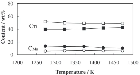
Figure 4 shows Ti content, CTi, and Mn content, CMn,
picked up from the surface composition of a coat derived from line analysis. No significant variations are seen in the temperature range 1273–1473 K for the 72 ks PC treatment, suggesting the surface composition is nearly equal those of the powder materials used for the PC treatment. This implies that the coat does not get any thicker unless the surface composition becomes different from the composition of the PC powder materials. It is to be noted that the contents of Al, CAl, V, and CV have been omitted because their small
variations revealed no clear trends, as can be seen in Fig. 3. Thus, CAl and CV were neglected in the results described
[image:4.595.311.539.74.195.2]below.
Figure 5 shows the values of CTiand CMn at the interface
between a substrate and a coating. Here CTi and CMn are
indicated in Fig. 3 by sine symbols, such as [CTi]c and
[CMn]c for coating, and [CTi]s and [CMn]s for substrate. Data
from both the substrate and coating sides of the interface are presented. The solid lines and broken lines represent their change with different PC treatment times at 1373 and 1323 K, respectively. Slight compositional changes with changing PC treatment time are observed, irrespective of processing temperature. The differences in Ti content on both sides of the interface,i.e., CTi in both the substrate and the coat, are Table 1 Change of thickness of PC-layer, distance from interface to
alumina particle, diameter of alumina particle with PC-treatment time.
times(ks) 18 36 72
W1(mm) 11 12 12
D1(mm) 7 8 8
ðD=WÞ1 0.6 0.7 0.7
1(mm) 10:3 10:3 10:3
W2(mm) 35 36 35
D2(mm) 24 23 22
ðD=WÞ2 0.7 0.6 0.6
2(mm) 20:5 20:5 20:5
thickness, W, distance, D, diameter,. W1,D1,1; 1323 K PC-treatment.
[image:4.595.46.292.94.210.2]W2,D2,2; 1373 K PC-treatment.
Table 2 Particles location and diffusion area in 72 ks PC-treated at temperature range of 1273–1473 K.
Temp.(K) 1273 1323 1373 1423 1473
W(mm) 11 12 35 34 34
D(mm) 7 8 22 22 22
(D=W) 0.6 0.7 0.6 0.6 0.6
RW(mm) 12 23 54 57 57
0 20 40 60
1250 1300 1350 1400 1450 1500
Temperature / K
Content / wt%
CTi
CMn
Fig. 4 Changes of CTiand CMnwith PC treatment temperatures. CTi, CMn;
Ti, Mn contents on the surface layer of 72 ks PC-treated specimens.
0 20 40 60 80
0 20 40 60 80
Time / ks
Content / wt%
CTi
CMn
[image:4.595.45.291.292.359.2] [image:4.595.313.540.621.736.2]relatively larger in the process at 1323 K than at 1373 K. The values of CMn exhibit a similar dependence on PC process
temperatures.
Figure 6 shows the PC temperature dependence of Ti and Mn contents at the interface between a substrate and a coating layer after a PC treatment for 72 ks. For both CTi and CMn,
differences in their values between the substrate side and the coat side become smaller as the treatment temperature increases, showing a tendency to get closer to each other. This means that the higher the PC temperature is, the closer the interface contents come to each other between the coat phase and the substrate phase.
In a 1373 K PC treatment for 36 ks, applied to an L12-type
alloy as a substrate, no coat formed on the cross section of the specimen. This differed from the case where an L10-type
alloy was adopted as a substrate, resulting in a decrease in Mn content within the range of 0.5mmrange from the surface, as found by line analysis.
4. Discussion
Before we begin our discussion, we sketch the results obtained in this study as follows. Within the range of 1273– 1473 K, the coat thickness was saturated in PC treatments lasting less than 18 ks in process time, irrespective of the process temperature, and exhibited no increase during process times of 18–72 ks. The coat thickness showed two different values: 10mmat 1323 K or under, and 35mmat 1373 or higher. The main purpose of this study was to investigate the factors determining the thickness growth of coats during PC treatment. The results obtained here, however, showed a different growth process than that expressing a parabolic saturation pattern,11)instead exhibiting temperature
depend-ence only at two values, as mentioned above. In the following discussion, therefore, we consider only the mechanism exhibiting the two-value temperature dependence.
4.1 Factors in increasing of coat thickness
In the first step, it must be considered that no coat was detected after a 1373 K PC treatment for 36 ks when the L12
-alloy was used as a substrate. This indicates clearly that when the PC powder has the same composition as the substrate, the coating process does not progress because the pressure
between vaporizations of the PC powder and of the substrate is at equilibrium. In other words, sedimentation of a coating layer due to PC treatment will be advanced when the surface composition of the coat differs from that of the PC powder, and is limited when the compositions are similar. Therefore, in the PC treatment, the coat thickness might be increased by increasing the diffusion rate of constituent elements in the coat; this will change the composition of the surface layer due to the diffusion to the substrate. The composition difference between the PC powder and the coat might be considered a factor in coat thickness. Actually, this experiment showed that the saturation of coat growth was detected when the surfaces exhibited the same composition, irrespective of the PC treatment temperatures, as shown in Fig. 4. That is, the vaporization pressure of the surface layer can be considered the same as that of the PC powder. In the following discussion regarding change in coat thickness, the change of surface composition must be taken into consideration as the most basic one.
As for changing of the surface composition with PC temperature, we have to discuss the diffusion of constituent elements. In this system, there are three factors for driving forces of the diffusion,i.e., PC temperature, the composition difference at two-phase interface between coat and substrate, and the interface character.
4.2 Interface structure affecting thickness growth It is worthy remark that two kinds of alumina particles formed in the coat at some depth from the surface, and that the size and depth depended on the PC treatment temperature. As far as we know, this is the first report of such formation of alumina particles. The formation may relate to the atmo-sphere in this PC treatment, as we describe in detail further below.
As shown in Figs. 2(a)–(b), the interface between the L12
-and L10-phases formed in the temperature range of 1373–
1473 K exhibits smooth morphology, while as shown in Fig. 2(c), the interface formed at 1273 K and that formed at 1323 K both exhibit irregular morphology, including many kinds of lines, such as short flat lines, concave curves, and convex curves. They are accompanying nodes at each terminal, and make sharp angles between adjoining them. From the morphology shown in Fig. 2(c), it can be estimated that the mobility of the interface,i.e., the diffusion rates of the constituent elements, is different in each small region of the interface. The structure of the irregular interface was not identified in this study. However, the maximum temperature at which an irregular interface will form is estimated to be in the range of 1323 to 1373 K, judging by the temperature dependence of the interface morphology and the thickness of the coat. Meanwhile, as shown in Table 1, the alumina particles in the coat were 1mmat 1323 K or below and 2mm at 1373 K or above. That is, the temperature dependence of the particle size is quite similar to that of coat thickness. From this similarity in temperature dependence, it may be inferred that the same factor contributes to the formation mechanisms of both the particle and the irregular interface. Therefore, in the following discussion, the formation mech-anism of the alumina particle must be considered.
As for the formation mechanism of the alumina particle, 0
20 40 60 80
1200 1250 1300 1350 1400 1450 1500
Temperature / K
Content / wt%
CTi
CMn
Fig. 6 Temperature dependence of Ti and Mn contents, CTiand CMn, near
[image:5.595.56.284.73.196.2]the following two processes may be considered. One relates to the alumina particle that was added to the PC powder as an inhibitor; that is, the inhibitor adhered to the substrate surface before the PC treatment and was detected after. The other process relates to the oxidized surface of the substrate; the oxidized surface was formed before evaporation gas began to be deposited, and reacted with the deposition layer during deposition. When the former process is possible, it is necessary to explain why particle size exhibits two values of 1 and/or 2mmand why the particles are smaller by one order of magnitude than the alumina particles as an inhibitor of 45–78mm. Furthermore, the reason why the alumina particle is formed inside the coat must also be explained.
On the other hand, when the oxidation process is applied, the oxidation of the L10-phase alloy at temperatures above
1173 K progresses at an extremely higher rate than that of the L12-phase alloy13) and the composition of the deposition
layer approach quickly to that of the L12-phase alloy because
of low diffusivity of the constituent elements in the oxidation surface. Hence a discussion of the formation of alumina particles must consider that substrate surface oxidation may be suppressed while the coat is being deposited. As described in Results, the deposition of evaporation gas proceeded at temperatures slightly lower than 1273 K, and then the substrate surface oxidation progressed from 1173 K to the lowest evaporation temperature. Since the rates of temper-ature increase in this experiment were all in same, irrespec-tive of PC treatment temperatures, the amount of oxidation was also independent of the PC treatment temperatures. Aggressive oxidation of the L10-phase alloy above 1173 K is
known to be due to the composite structure of the oxide TiO2
and Al2O3.5) As described in Experimental method, the
pressure in the PC treatment chamber was measured by a vacuum gauge located in the low-pressure side of a diffusion pump, and was confirmed to be on the order of 104Pa.
However, actual pressure on a PC treatment specimen was considered to be at least one or two order of magnitude higher than that measured because of the long distance from the specimen to the gauge, which was connected by a vacuum-rubber tube 1 m in length and 9mm in inner diameter. Accordingly, the formation-volume ratio, Vr/Va, of the TiO2-phase (Vr) to the Al2O3-phase (Va) may differ from
that formed in air, while the formation of the TiO2-phase is
inevitable.5)Furthermore, the TiO2-phase may be reduced by
the surrounding Al element during the deposition of vapor-ization gas in the PC treatment. According to above-mentioned conditions, it can be explained why particles in the coating layer formed at 1373 K or above are larger than those formed at 1323 K or below. That is, the TiO2 in the
oxidation surface formed in the range of 1173 to 1273 K will be changed into Al2O3 by the reduction process due to the
consequent deposition of vaporization at temperatures above 1273 K. The TiO2 is mostly reduced at 1373 K or above,
while the reduction is only partial at 1323 K or below. So a portion of the TiO2might remain at the substrate surface at a
PC treatment temperature of 1323 K or below. The newly formed Al2O3 resulting from the reduction process may
coagulate to the Al2O3 formed during oxidation.
On the other hand, the reduction process due to Al elements may be affected by the PC treatment temperature
and by the amounts of the surrounding elements, Al and/or Ti. From the results obtained, the reduction process pro-gressed entirely and partially at temperatures above 1373 K and below 1323 K, respectively. In addition, the retained TiO2-phase may be located at the interface between the
substrate and the L12-phase of the coating layer. Thus the
retained TiO2 phase on the interface might act as a barrier
against diffusion of the constituent elements, and might limit the coat’s thickness.
4.3 Effects of PC-temperature and composition differ-ence between coat and substrate on the composition change of the coat
The effect of the composition difference at two-phase interface on the composition change of coating layer should be discussed. An equilibrium composition at the two-phase boundary of the L12- and L10-phases was described in a
report on thermocouple experiments of those phases.14)
According to the report, their compositions approach each other as temperature increases within the range of 1273– 1473 K. As shown in Fig. 3, the contents of Ti and/or Mn in the L12-phase are so different from those in the L10-phase,
while the content differences of Al and/or V are not so different. The differences between the Ti and Mn contents decrease as the PC temperature increases, as shown in Fig. 6. That is, the temperature dependence is similar to that with the phase equilibrium described above. Generally, an increase of composition difference at two-phase interface increases the diffusion rate of constituent elements. However, in this system, the composition difference at two-phase interface decreased with increasing of PC temperature. Therefore the change of the composition difference by increasing of PC temperature causes a negative effect on the diffusion rate of constituent elements.
Meanwhile, PC temperature in itself is well known to increases the diffusion rate of constituent elements; the increase of PC temperature increases the composition change of coating layer.
4.4 Resulting the composition change of coating layer with PC treatment by the thee factors
increasing PC temperature. Thus the coat exhibits a constant thickness of 34mm at 1373 K or higher, and of 12mm at 1323 K or less.
Research on these issues should be undertaken soon, and they should precisely examine the interface via high-resolution TEM analysis.
5. Summary
The coating of the L12-phase of (AlMn)3Ti (1%V) alloy on
the L10-phase substrate of TiAl (1%Mn, 1%V) alloy was
examined in the range of 1273–1473 K for 8–72 ks by the pack-cementation method. The results obtained are as follows:
(1) The L10-L12-phases show equilibrium at PC processing
temperatures between 1273 and 1473 K, composing a coat of the L12 phase on the surface of the substrate.
(2) The layer thickness W is 35mm at PC processing temperatures between 1373 and 1473 K, while it is 11– 12mm between 1273 and 1323 K, thus showing a remarkable difference between 1323 and 1373 K. (3) W remains constant at PC processing times of 18–72 ks;
in periods of less than 18 ks, W increases.
(4) Regardless of the variation in PC processing temper-atures, alumina particles with diameters of 1–2mmare formed almost parallel to, and at a depth of 0.3–0.4 W from, the surface inside the coating layer.
REFERENCES
1) Martin J. Blackburn and Michael P. Smith: U.S. Patent; 4,292,077, (1981).
2) S.-C. Hunang and D. S. Shih:Microstructure/Property Relationships in Titanium Aluminides and Alloys, ed. by Y.-W. Kim and R. R. Boyer (Warrendale, PA.: TMS, 1990) 105–122.
3) T. Kawabata, M. Tamura and O. Izumi: Scr. Metall.,22(1988) 1725– 1730.
4) T. Tsujimoto and K. Hashimoto:High-Temperature ordered Interme-tallic Alloys III, ed. by C. T. Liuet al.(Pittsburg. PA: MRS,1989) 391– 396.
5) E. Kobayashi, M. Yoshiwara and R. Tanaka:Proc. 1st Jpn Int. SAMPE Symp.(The NIKKAN KOGYO SHINBUN, LTD. 1989) Nov. 151–153. 6) S. Taguchi, T. Shibata and A. Murakami: Oxid. Met.41(1994) 103–
113.
7) T. Shimizu, T. Iikubo and S. Isobe: Mater. Sci. Eng., A153(1992) 602–107.
8) J. Y. Park, S. W. Park, H. N. Lee, M. H. Oh and D. W. Wee: Scr. Mater. 36(1997) 801–806.
9) H. Mabuchi, T. Aasi and T. Kawakami: Scr. Metall.23(1989) 685– 689.
10) A. Takei and A. Ishida:Gakushin Tainetu-Kinzoku-ZairyouNo. 123 Reports,31(1990) 327–330.
11) H. Mabuchi, H. Tsuda, T. Kawakami, S. Nakamatsu, T. Matsui and K. Morii: Scr. Mater.41(1999) 511–516.
12) K. Hashimoto, K. Kasahara, E. Abe, T. Kimura, M. Nakamura and Y. Yamamoto:NRIM Research Activity, (2000) 30–32.
13) T. Yoshioka and O. Ohashi: Jpn. Inst. Metals,64(2000) 1127–1132. 14) J. G. Kim, T. Kimura, K. W. Gao, K. Hashimoto and L. Qiao: Mater.
![Figure 5 shows the values of CMn]s for substrate. Datafrom both the substrate and coating sides of the interface arepresented](https://thumb-us.123doks.com/thumbv2/123dok_us/356529.533464/4.595.313.540.621.736/figure-values-substrate-datafrom-substrate-coating-interface-arepresented.webp)