Abstract—Four-wire microgrids and distribution systems are inherently unbalanced with the presence of negative and zero sequence components in voltages and currents. In small autonomous systems the imbalance, in addition to the harmonic distortion produced by non-linear loads, can significantly affect power quality, loadability and stability of the system. Furthermore, in isolated networks with significant generation from intermittent renewable energy sources, the stiffness of the system is reduced and this could amplify the effects of imbalance on the stability and power quality. To mitigate some of these problems, a novel methodology based on the application of a 4-leg Active Power Filter (APF) is proposed in this paper. The control of the compensator is based on the Conservative Power Theory (CPT) augmented by Resonant Controllers. The behaviour of the proposed system is demonstrated using an experimental prototype deployed in a laboratory scale microgrid
Index Terms— Active power filter, conservative power theory, resonant control, microgrids, imbalance, harmonic distortion.
I. INTRODUCTION
ower systems are undergoing a paradigm change, moving from centralised distribution to distributed generation including microgrids (MGs) and smart grids. In distributed generation systems it is expected that a relatively high penetration of electrical energy provided by Non-Conventional Renewable Energy (NCRE) sources of intermittent nature will be present, usually connected to the MG using power electronic converters which can affect the stiffness of the network. Droop control is one of the methods typically used to share active and reactive power between these generating units [1] [2] and this may lead to some variations in the microgrid fundamental frequency: this must be considered when designing control systems for APFs applications.
An MG could be implemented as a low voltage power
C. Burgos-Mellado and C. Hernández-Carimán would like to thank the support of the Conicyt scholarship programme for postgraduate studies.
This work has been partially supported by the Conicyt grants, FONDECYT 1140775 and FONDEF ID14I10063. The financial support of the Conicyt-Basal project FB0008 is also kindly acknowledged.
The authors would like to thank Prof. Claudio Cañizares, University of Waterloo, for kindly sharing with us information related to the operation of a Canadian microgrid.
C. Burgos-Mellado, C. Hernández-Carimán, R. Cárdenas and D. Sáez, are with the Department of Electrical Engineering, FCFM, University of Chile, Av. Tupper 2007, 8370451, Santiago Chile (e-mail: [email protected]). M. Sumner and A. Costabeber are with the PEMC Group, University of Nottingham, NG72RD Nottingham, U.K., (e-mail: [email protected]).
Helmo Morales is with the Group of Automation and Integrated Systems, Universidade Estadual Paulista Julio de Mesquita Filho, 18087-180 Sorocaba, Brazil, (email: [email protected])
distribution system operating in grid connected or islanded mode [3] [4] [5] feeding single-phase linear and non-linear loads, typically using three-phase 4-wire topologies [6] [7]. These inherently unbalanced loads produce negative and zero sequence components in the currents and voltages of the network. According to [8], the ratio of unbalanced to balanced loads will increase in the future with higher penetration of hybrid and electric vehicles, heat pumps, etc. In this context some well-known problems related to load imbalance could appear [9]. For instance negative sequence voltage components produce oscillations in the torque of induction machines and synchronous generators. This in turn may reduce the efficiency and useful life of these machines [8] [10]. Other effects of imbalance are localised heating in machines and power converters, and reduced loadability of conventional synchronous generators (see [10] [11]) which affects the stability of the MGs [11]. The zero sequence current flowing through the neutral wire can produce additional problems such as overloading of the neutral conductor [9] [12] and malfunction of sensitive equipment due to ground voltage fluctuations if the current flowing through the neutral wire is large and/or the impedance of the neutral connection has a relatively large magnitude [9] [12]. In addition the load served by a 4-leg MG could be of non-linear nature [12] [13] [14], generating distorted load currents which could also diminish the loadability of the power generating sources in the microgrid.
Several solutions have been proposed in the literature to compensate imbalance and harmonic distortion [15] [16] [17]. Among them Active Power Filters (APFs) are considered appropriate topologies with several papers discussing issues such as the design of APF’s passive components [6] [12], compensation objectives [8] [18], serial and/or parallel connection of APFs [6], etc. The performance of the APF is heavily dependent on the control system applied which is usually based on a power theory, with many applications using the p-q or modified p-q power theories. However, one of the reported disadvantages of these methodologies is their sensitivity to distortion in the signals and the generation of unwanted current components in some operating conditions [19] [20].
The experimental validation of the control systems and hardware topologies proposed in this work has been partly based on the operating conditions of a real MG implemented in the north of Canada. The values of Total Harmonic Distortion (THD), currents imbalance, variations of the load, etc. are based on the experimental data measured at this location. From this data (see Table I on Section IV) is concluded that the zero sequence current components can have a relatively large magnitude when a real case of an isolated
Experimental Evaluation of a CPT-Based 4-leg Active
Power Compensator For Distributed Generation
Claudio Burgos-Mellado, Carlos Hernández-Carimán, Roberto Cárdenas,
IEEE Senior Member
, Doris
Sáez,
IEEE Senior Member
, Mark Sumner,
IEEE Senior Member
, Alessandro Costabeber,
IEEE
Member
and Helmo Morales
microgrid operating at a remote location is considered. Most of the previous publications related to the use of active power filters in distributed generation are focused to 3-leg applications without discussing the problems associated with low voltage distribution systems which are mainly 4-wire systems. Therefore in this work the control of a 4-leg APF based on the Conservative Power Theory (CPT) is presented. Unlike previous publication where a 4-leg converter is controlled using a fixed-duty cycle of 50% in the 4th leg (see [21]) in this paper full utilisation of the dc-link is achieved using proper modulation algorithms and control systems. In addition resonant controllers instead of low dynamic controllers, as those reported in [21] [22], are designed and implemented in this application.
Using a CPT based algorithms is relatively simple to separate the unwanted current into several decoupled components, for instance calculating which components are produced by unbalanced or non-linear loads and which are due to power supply distortion (for accountability purposes [23] [24]). This is important considering that a typical microgrid has several power converters interfacing the intermittent NCRE sources to the MG. Therefore it would be advantageous to use the residual VA capability of these converters to share the compensation of unwanted currents. This in turn could reduce the rating of the APF.
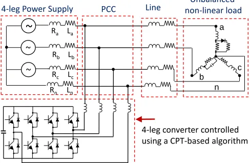
The proposed compensating topology is shown in Fig. 1. On the left hand side the Thévenin equivalent combination of the 4-leg power supplies, obtained at the Point of Common Coupling (PCC) is shown. The linear/non-linear load and the compensator are connected at the PCC. If an energy storage system is required, this could be connected to the dc-link of the APF to provide active power to the MG. The contributions of this paper are:
[image:2.612.51.295.544.703.2] In microgrids relatively large variations in the electrical frequency may occur. The sensitivity to grid frequency variations is a known limitation of the CPT [21] [24], and this paper proposes and validates an implementation approach that shows limited impact of frequency variation on the APF performance. This is confirmed by the experimental results presented in this paper where the performance of the CPT-based power compensator algorithm has been experimentally evaluated during transient operation, and under grid frequency
Fig. 1. Proposed control strategy for a 4-leg compensator connected to a distribution network.
variations.
Unlike previous papers [21] [23] [24] [25], in this work the CPT is applied to 4-wire systems considering full control of the 4 legs in the APF, to regulate the positive, negative and zero sequence voltages synthesised by the power converter. This includes operation of the CPT compensator with single phase non-linear loads.
The current control is realised using 7 paralleled-connected self-tuning resonant controllers in each phase. The tracking of the resonant frequency is realised using a tuning algorithm, based on the real-time discretization of controllers implemented using the bilinear transform with frequency prewarping. As discussed in [26] this discretisation method has important advantages, in terms of preserving the resonant frequency accuracy particularly when high order harmonics have to be compensated. To the best of the author’s knowledge, self-tuning adaptive algorithms for the bilinear transform with frequency prewarping have not been discussed in the literature where most of the reported applications are based on the conventional bilinear transform [27].
The rest of this paper is organized as follows. In Section II the conservative power theory is briefly introduced. In Section III the proposed control systems for the 4-leg APF are discussed. The operating conditions for the small microgrid in northern Canada are briefly described in Section IV. In Section V experimental results obtained from a small prototype are presented. Finally an appraisal of the proposed methodology is summarised at the Conclusions.
II. CONSERVATIVE POWER THEORY (CPT)
The CPT has been proposed as a new power-theory to analyse distribution systems and microgrids, where single phase loads, non-linear loads, and strong harmonic distortion could be present [24] [25]. Using the CPT, an orthogonal separation of the unwanted current components can be achieved to allow selective compensation of them. Moreover the implementation of a CPT-based control algorithm can be realised in the stationary a-b-c frame: it does not require a synchronous rotating reference frame [24]. The CPT has been discussed before (e.g. [24] [28, 29]). However, for completeness a brief introduction is presented here.
To implement the CPT two instantaneous quantities are defined [24] [28]. The first is the instantaneous power which corresponds to the scalar product:
𝑝(𝑡) = 𝑣 ∘ 𝑖 = [𝑣𝑎 𝑣𝑏 𝑣𝑐] ∘ [𝑖𝑎 𝑖𝑏 𝑖𝑐]𝑇 (1) The second is the instantaneous reactive energy defined as: 𝑤(𝑡) = 𝑣̂ ∘ 𝑖 = [𝑣̂𝑎 𝑣̂𝑏 𝑣̂𝑐] ∘ [𝑖𝑎 𝑖𝑏 𝑖𝑐]𝑇 (2) Where 𝑣̂ is the vector containing the unbiased integral of the phase voltages. This vector 𝑣̂ is calculated as:
𝑣𝜇
̂ = ∫ 𝑣𝜇(𝜏)𝑑𝜏 𝑡
0
− 𝑣̅∫ 𝜇, (3)
Notice that the index “μ” (μ=a,b,c) represents the variable per phase and the term 𝑣̅∫ 𝜇, corresponds to the average component of each phase voltage integral. For the application depicted in Fig. 1, phase voltages are measured with respect to the neutral conductor at the PCC [24]. Considering the mean
a
b
c
Unbalanced non-linear load Line
4-leg Power Supply
~
~
~
4-leg converter controlled using a CPT-based algorithm
Ra La
Rb Lb
Rc Lc
Rn Ln n
values of (1-2), the active power (P) and reactive energy (W) are defined as:
𝑃 =1
𝑇∫ 𝑣 ∘ 𝑖 𝑑𝑡 𝑊 = 1
𝑇∫ 𝑣̂ ∘ 𝑖 𝑑𝑡 𝑇
0 𝑇
0
(4)
Based on (1)-(4), the load current can be decomposed in five orthogonal components. These are: (i) balanced active currents (𝑖𝑎𝜇𝑏 ), (ii) balanced reactive currents (𝑖𝑟𝜇𝑏 ), (iii) unbalanced active currents (𝑖𝑎𝜇𝑢 ), (iv) unbalanced reactive currents (𝑖𝑟𝜇𝑢) and (v) void currents (𝑖𝑣𝜇) [24] [28].
The balanced active currents are defined as: 𝑖𝑎𝜇𝑏 =
𝑃 𝑽2𝑣𝜇= 𝐺
𝑏𝑣 𝜇
(5)
such that 𝑽 = √𝑉𝑎2+ 𝑉𝑏2+ 𝑉𝑐2 is the collective RMS value (Euclidean norm) of the voltage, parameter 𝐺𝑏 is the equivalent balanced conductance and 𝑃 is the active power.
The balanced reactive currents are defined as: 𝑖𝑟𝜇𝑏 =
𝑊 𝑽̂2𝑣̂𝜇= ℬ
𝑏𝑣̂ 𝜇
(6)
Such that 𝑣̂𝜇 is the unbiased voltage integral, 𝑽̂ is the collective RMS value of the unbiased voltage integral, ℬ𝑏 is the equivalent balanced reactivity and 𝑊 is the reactive energy (see [24] [28]).
The unbalanced currents are defined as:
𝑖𝜇𝑢= 𝑖𝑎𝜇𝑢 + 𝑖𝑟𝜇𝑢 = (𝐺𝜇− 𝐺𝑏)𝑣𝜇+ (ℬ𝜇− ℬ𝑏)𝑣̂𝜇 (7) Where the per-phase conductance and per-phase reactivity are defined as:
𝐺𝜇= 𝑃𝜇 𝑉𝜇2
𝑣𝜇 𝑎𝑛𝑑 ℬ𝜇= 𝑊𝜇 𝑉̂𝜇2
𝑣̂𝜇
(8)
Notice that the unbalanced currents (7) only exist if 𝐺𝜇≠ 𝐺𝑏 and/or if ℬ𝜇≠ ℬ𝑏, i.e. when the load is unbalanced. In single-phase circuit, the currents of (7) disappear.
The void currents are the remaining currents that do not transfer active or reactive energy, and are given by:
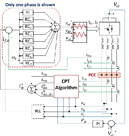
𝑖𝑣𝜇= 𝑖𝜇− 𝑖𝑎𝜇𝑏 − 𝑖𝑟𝜇𝑏 − 𝑖𝜇𝑢 (9) All the current components (i.e. 𝑖𝑎𝜇𝑏 , 𝑖𝑟𝜇𝑏 , 𝑖𝑎𝜇𝑢 , 𝑖𝑟𝜇𝑢 and 𝑖𝑣𝜇) are orthogonal. The implementation of the CPT used in this paper is shown in Fig. 2. Voltage and current transducers are used to measure the load currents and voltages at the PCC. In this work a Band-Pass Filter (BPF) is used to obtain the unbiased integral of the voltages (i.e. to obtain [𝑣̂𝑎 𝑣̂𝑏 𝑣̂𝑐]). Notice that this technique is widely used for the estimation of the magnetic flux in electrical machines [30]. The BPF eliminates the dc component of the signals and behaves as an ideal integrator for frequencies above 3Hz (see [30]).
Low Pass Filters (LPFs) are used to obtain the average value of the power P and the reactive energy W in each phase. The effective voltages and the Euclidian norms required by the CPT algorithm are calculated in the block labelled “RMS Calculator” shown at the top right of Fig. 2. This RMS calculator utilises a filter with a transfer function equal to that used in the others LPFs shown in Fig. 2. This filter has been designed with a relatively high cut-off frequency to avoid jeopardising the overall dynamic response. Notice that the
application of filters is also necessary to implement APFs based on other power theories, for instance p-q power theory [19, 31].
As shown in the left hand side of Fig. 2, the outputs of the CPT algorithm are the currents [𝑖𝑎𝜇𝑏 , 𝑖𝑎𝜇𝑢 , 𝑖𝑟𝜇𝑏 , 𝑖𝑟𝜇𝑢, 𝑖𝑣𝜇]. These currents are used to calculate the references required by the current control.
An important remark related with the practical implementation of the CPT algorithm is the impact of grid frequency variations. As discussed above, the calculation of the unbiased integral (3); of the active power and reactive energy (4); and of the Euclidean norms requires band pass filters or low pass filters. In previous works [21], these filters have been implemented using moving average digital filters, resulting in selective frequency responses but highly sensitive to grid frequency variations. From a practical perspective, moving average filters must be made frequency adaptive using the frequency measured by a PLL. This leads to considerable computational burden that might reduce the attractiveness of CPT based filters. In this work, a different approach has been considered: rather than implementing highly selective and adaptive filters, fixed filters with lower selectivity have been adopted. Considering that the range of frequency variations is expected to be narrow, also the impact on filtering will be limited. This choice simplifies the structure of the CPT algorithm, with limited impact on the effectiveness of the algorithm, as demonstrated in the experimental results under grid frequency transients.
A final comment about the implementation of the CPT is related with the practical need for complete current decomposition. If the APF is designed to fully compensate the load non-idealities, only the balanced active components (5) of the load current must be evaluated, and all the remaining unwanted components can be derived subtracting the active balanced current from the load current. In this case, the computational burden of the CPT algorithm will be much reduced. On the other hand, if the APF has small power rating, or the active filtering is performed using the residual power capability of distributed generators, it might not be possible to compensate for the non-idealities in full, but an external command could be sent to another APF or power converter (with residual VA capability available) to demand for the compensation of a specific set of unwanted components. For the sake of generality, this paper addresses the case where a full current decomposition is implemented, giving maximum flexibility in the selection of the compensation objectives.
The capability of separating the unwanted signals into several orthogonal components (which can be compensated using several power converters) is a very powerful feature of the CPT algorithm described in (1)-(9).
III. PROPOSED CONTROL SYSTEM
Resonant controllers have been selected for this application because they can regulate sinusoidal signals with zero steady state error in a-b-c coordinates. Moreover they have better dynamic response than that obtained with other control topologies (e.g. repetitive controllers [22]). In each phase, a PI controller and 7 resonant controllers, tuned to regulate the fundamental and the 2nd, 3rd, 4th, 5th, 6th and 7th order harmonics, have been implemented in this work. These frequencies have been selected considering the harmonic distortion presented in the case-study microgrid discussed in Section IV. However in other cases the elimination of more (or less) harmonic frequencies could be desirable by parallel connecting more resonant controllers.
[image:4.612.98.510.55.284.2]Regarding implementation issues, it is well-known that Digital Signal Processors (DSPs), have experienced an exponential development in processing power [32]. Therefore
Fig. 3. Proposed current control system.
even when the proposed control algorithm, based on 21 self-tuning resonant controllers, seems relatively complex it is simple to implement using a commercial DSP with a good processing capability and a suitable FPGA platforms. For instance the authors have implemented high order resonant control systems using the low cost Texas Instrument processor, TMS320C6713 DSK augmented with an Altera FPGA board (see [33]). A detailed analysis of implementation issues is considered outside the scope of this paper.
In a parallel topology each resonant controller can be separately designed assuming that the response of each controller is selective and only alters the frequency response around its resonant peak [34]. This simplifies the design procedure significantly.
A. Control System Design
The design and digital implementation of proportional resonant (PRs) controllers has been broadly discussed in previous publications (see [26] [33] [34] [35]) and is briefly summarised here.
In the s plane a PR controller, designed to regulate a current of frequency j can be written as:
𝐺𝑐𝑗(𝑠) = 𝑘𝑝𝑗+
𝑘𝑖𝑗𝑠 𝑠2+ 2𝜁𝜔
𝑗𝑠 + 𝜔𝑗2
(10)
where is the controller damping and 𝑘𝑝𝑗, 𝑘𝑖𝑗 are the controller gains. Notice that (10) is equivalent to the transfer function of a PI controller when 𝜔𝑗= 0.
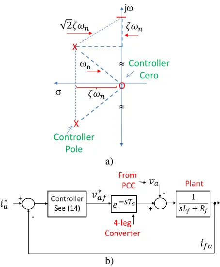
The poles and zero of the resonant part of the PR controller (see the right side term of (10)) are shown in Fig. 4(a). Notice that in this graphic 𝜔𝑗is defined as 𝜔𝑗 = 𝜔𝑛. Using Fig. 4(a) and the pole-zero placement method is relatively simple to design the term 𝜔𝑐 = 𝜁𝜔𝑗 in order to achieve a given bandwidth [36].
[image:4.612.71.277.496.714.2]Assuming that the term 𝜔𝑐 in (10) is very small compared to 𝜔𝑛, the peak amplitude (P) of the resonant part of the Fig. 2. Calculation of the compensating currents using the conservative power theory. Only currents of phase-a are shown.
~
~
~
Load
a b c
n
X
X
X
LPF
X
X
X
BPF RMS Calculator
X
Wa
1/u
X
P
1/u
X
W
1/u
X 1/u
Pa X
+ + +
-X
+
-X
-+
Only one phase is shown
4-leg equivalent power source
controller is obtained when 𝑠 = 𝑗𝜔𝑛. From Fig. 4(a) it is also simple to conclude that for 𝑠 = 𝑗(𝜔𝑛+ 𝜔𝑐) and 𝑠 = 𝑗(𝜔𝑛− 𝜔𝑐) the gain is reduced in 3db, corresponding to an amplitude value of 𝑃 √2⁄ . Therefore, the term 𝜔𝑐 could be used to set the band-pass of the resonant frequency and helps to modify the selectivity of the PR controller of (10) (see [36]). In this work 𝜔𝑐=5rads-1 has been selected and this values allows to achieve good dynamic performance in the current control loop, as demonstrated by the experimental results presented in this work.
The control diagram for design purposes is shown in Fig. 4(b). Assuming that each controller could be separately designed and that the voltage at the PCC is an external perturbation (unaffected by the operation of the APF), the following transfer function can be derived from Fig. 4(b).
𝑖𝑓𝑎 𝑖𝑎∗
= 𝐺𝑐𝑗(𝑠)𝑃𝑙𝑎𝑛𝑡(𝑠)𝑒 −𝑆𝑇𝑠
1 + 𝐺𝑐𝑗(𝑠)𝑃𝑙𝑎𝑛𝑡(𝑠)𝑒−𝑆𝑇𝑠
(11)
Where the term plant in (11) is defined as 𝑝𝑙𝑎𝑛𝑡(𝑠) = 1 (𝑠𝐿⁄ 𝑓+ 𝑅𝑓) and ifa is the current injected by the active filter in the phase “a” (see Fig. 3) . Notice that Lf, Rf are the inductance and the resistance per phase (respectively) of the impedance connecting the APF to the PCC. A delay of one sample in (11) is used to represent the transfer function of the 4-leg APF. This delay is a simplified representation of the effects associated to the power converter modulation algorithm.
Adding the transfer functions of the controllers depicted in Fig. 3, the transfer function of the whole current control system (phase A) is obtained as:
a)
b)
Fig. 4. a) Pole and zero placement of the resonant part of the PR controller [see the right side term of (10)].b) Control system considering the plant and the converter.
𝑣𝑎𝑓∗ (𝑠) [𝑖𝑎∗(𝑠) − 𝑖𝑓𝑎(𝑠)]
= 𝑘𝑝𝑇+ ∑ [
𝑘𝑖𝑗𝑠 𝑠2+ 2𝜁𝜔
𝑗𝑠 + 𝜔𝑗2 ] 7
𝑗=0
(12)
where 𝑘𝑝𝑇= ∑ 𝑘𝑝𝑗 is the overall controller gain. Notice that (12) includes the PI controller.
[image:5.612.322.561.55.90.2] [image:5.612.316.565.226.368.2]There are many control design methods reported in the literature for determining the controller gains 𝑘𝑝𝑗 and 𝑘𝑖𝑗 [see (10)] [33] [34]. In this work linear control tools as Bode Diagrams and Root Locus reshaping have been applied to design each of the eight parallel controllers shown in Fig. 3. Assuming that the resonant controllers alter only the frequency response around its resonant frequency, each controller (as shown in Fig. 3) has been designed for a phase margin of at least 50 degrees and a bandwidth of 30rads-1. The Bode diagram of the proposed control system is shown in Fig. 5.
Fig. 5. Bode diagram of the current control system.
In this work the z-plane implementation of (10) is realised by applying the bilinear transform with frequency pre-warping to (12). This discretization method has been selected because it preserves, with relatively good accuracy, the resonant frequency and the phase margin of the original design in the “s” plane [26] [34]. Therefore, the digital version of (12) is obtained by replacing the Laplace operator “s” using:
𝑠 = 𝜔𝑗
𝑡𝑎𝑛 (𝜔𝑗 𝑇𝑠
2) (𝑧 − 1
𝑧 + 1) = 𝑘𝑇𝜔𝑗( 𝑧 − 1 𝑧 + 1)
(13)
where 𝜔𝑗 is the j-th controller resonant frequency, Ts is the sampling period and 𝑘𝑇𝜔𝑗 is a non-linear function of the resonant and sampling frequencies. Replacing (13) in (12), the z-plane transfer function of the current control system is obtained as:
𝑣𝑎𝑓∗(𝑧) [𝑖𝑎∗(𝑧) − 𝑖𝑓𝑎(𝑧)]
= 𝑘𝑝𝑇
+ ∑ [
𝑘𝑇𝜔
𝑗𝑘𝑖𝑗(𝑧
2− 1) (2𝜁𝜔𝑗𝑘𝑇𝜔𝑗+ 𝑘𝑇𝜔𝑗
2 + 𝜔
𝑗2) 𝑧2+ 2 (𝜔𝑗2− 𝑘𝑇𝜔𝑗
2 ) 𝑧 + (𝑘 𝑇𝜔𝑗
2 + 𝜔
𝑗2− 2𝜁𝜔𝑗𝑘𝑇𝜔𝑗)
] 7
0
(14) Notice that (14) is the transfer function of a self-tuning resonant control system which can be used to maintain the control system tuned in spite of changes in the fundamental frequency (e=1). In this work the value of 1 is estimated using a PLL (as shown in Fig. 3) and used to recalculate the values of 𝑘𝑇𝜔𝑗 on (13)-(14), updating the controller coefficients.
j
O X
n
X
Controller Pole
Controller Cero
20 30 40 50 60 70
Mag
ni
tud
e
(d
B)
100 101 102 103 104 105
Frequency (rad/s) PI controller
[image:5.612.60.287.419.694.2]To the best of our knowledge, the implementation of self-tuning resonant controllers, using the bilinear transform with frequency-pre-warping, has not been reported before.
B. Current Components Supplied by the APF.
As shown in Fig. 2 and from (5-9), the CPT algorithm separates the load current into five orthogonal components [𝑖𝑎𝜇𝑏 , 𝑖𝑎𝜇𝑢 , 𝑖𝑟𝜇𝑏 , 𝑖𝑟𝜇𝑢, 𝑖𝑣𝜇]. It is assumed that the load active balanced current 𝑖𝑎𝜇𝑏 is supplied by the power source, and all the other components are supplied by the APF. Therefore the unwanted current components being compensated by the APF are obtained as:
𝑖𝜇∗= 𝑖𝑎𝜇𝑢 + 𝑖𝑟𝜇+ 𝑖𝑣𝜇
(15) where 𝑖𝑟𝜇 = 𝑖𝑟𝜇𝑏 + 𝑖𝑟𝜇𝑢 [see (6-7)]. If the dc-link capacitor of Fig. 1 is floating, the 4-leg APF has to supply the converter losses from the grid. Therefore a balanced active current component has to be added to (15). This is obtained as:
𝑖𝑎𝜇_𝑑𝑐𝑏 = 𝑃𝑑𝑐
𝑽2𝑣𝜇
(16)
where Pdc is obtained from a PI controller (as shown in Fig. 3). Using (15)-(16), the current references are obtained as:
𝑖𝜇∗= 𝑖𝑎𝜇𝑢 + 𝑖𝑟𝜇+ 𝑖𝑣𝜇+ 𝑖𝑎𝜇_𝑑𝑐𝑏
(17) As shown in Fig. 3, the current references (𝑖𝑎∗, 𝑖𝑏∗, 𝑖𝑐∗) are processed by 24 controllers (8 per phase, see Fig. 3) generating three instantaneous voltages 𝑣𝑎𝑓∗ , 𝑣𝑏𝑓∗ and 𝑣𝑐𝑓∗ . These voltages are modulated by the 4-leg converter using a sine-weighted PWM algorithm implemented in the DSPACE experimental platform discussed in Section V. In order to achieve full utilisation of the dc-link, a common voltage component is added to the modulation signals of all the four legs, including the neutral leg. This additional component is derived according to the well-known Min-Max algorithm using the methodology proposed in [37, 38]. This algorithm is briefly summarised below.
The phase to neutral voltages 𝑣𝑎𝑓∗ , 𝑣𝑏𝑓∗ and 𝑣𝑐𝑓∗ are calculated as:
𝑣𝑎𝑓∗ = 𝑣𝑎𝑧∗ − 𝑣𝑓𝑧∗
(18)
𝑣𝑏𝑓∗ = 𝑣𝑏𝑧∗ − 𝑣𝑓𝑧∗ (19)
𝑣𝑐𝑓∗ = 𝑣𝑐𝑧∗ − 𝑣𝑓𝑧∗ (20)
where the subscripts a,b,c, f represent the four legs of the APF and the subscript “z” is used to identify a fictitious neutral point which is located at a mid-point in the dc link capacitors. The additional component 𝑣𝑓𝑧∗ of (18)-(20) is derived using the Min-Max algorithm [37], where the common component added to each modulation signal is:
𝑣𝑓𝑧∗ = −
𝑚𝑖𝑛(𝑣𝑎𝑓∗, 𝑣𝑏𝑓∗, 𝑣𝑐𝑓∗) + 𝑚𝑎𝑥(𝑣𝑎𝑓∗, 𝑣𝑏𝑓∗, 𝑣𝑐𝑓∗)
2
(21)
This guarantees maximum line to neutral voltage generation capability, and therefore maximum utilisation of the dc-link voltage, which is favourably compared to simpler solutions were the 4th leg is modulated at 50% duty cycle and the peak line to neutral voltage is constrained to half the dc-link voltage
[21]. It can also be shown that the Min-Max method discussed in [37, 38] is equivalent to Space Vector Modulation and, as a result, the line to neutral voltage could increase up to 15.4% when compared to the case where a 50% duty cycle is used for the 4th leg.
IV. OPERATING CONDITION OF THE CASE-STUDY MICROGRID To validate the performance of the proposed compensator, the operating conditions of a microgrid located in the North of Canada have been analysed. The population of this community is about 1000 inhabitants.
The microgrid power sources are three diesel generators (0.4 MW, 0.6 MW, 1 MW), 3x10 kW Bergey wind turbines, a 30 kW Wenvor wind turbine and a 10kW solar PV array. Fig. 6 shows the unifiliar diagram of the microgrid power system. The operating conditions, measured during the summer season are presented in Table I. For the experimental work the unbalanced currents shown on this table were scaled, using per unit analysis, to currents which could be handled by the experimental prototype built at the Power Electronic Lab, University of Chile.
It is important to highlight that the values shown in Table I were used to set the minimum operating conditions for the proposed APF. However, in order to test the performance of the proposed system considering the worst case situation, in some of the experimental results discussed in the next section, higher values of THDs, than those shown on Table I, were used.
The frequency variation of the microgrid used as the case study in this work is shown in Fig. 7. However, for the experimental work presented in this work, the base frequency is set to 50Hz corresponding to the nominal frequency used in Chile.
TABLE I
MICROGRID OPERATING CONDITIONS
Description Values Units Active power abc 458.41 kW Reactive power abc 78.69 kVAR
Voltage a RMS 605.09 V
Current a RMS 172.50 A
Current b RMS 333.07 A
Current c RMS 247.14 A
Current imbalance neg seq 18.70 A Current imbalance zero seq 20.74 A
Current a THD 7.49 %
Current b THD 5.63 %
Current c THD 5.25 %
Fig. 6. Unifiliar diagram of the case-study Microgrid.
~
CPT
Compensator
Loads
PV 10kW 0.4, 0.6, 1MW
Fig. 7. Frequency variation.
V. EXPERIMENTAL RESULTS
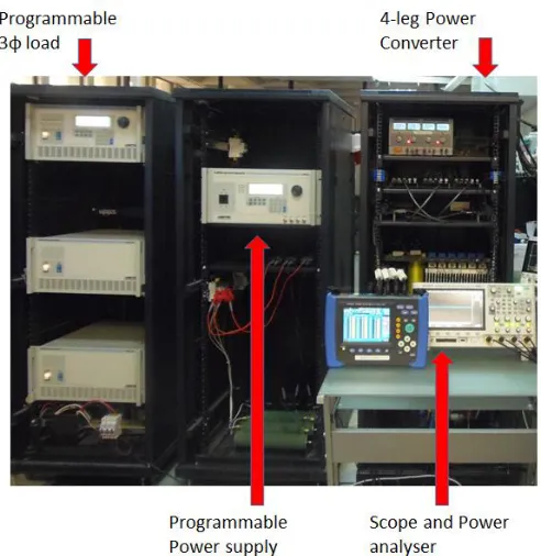
The control systems depicted in Fig. 3 have been implemented in the experimental system shown in Fig. 8. In this work an Ametek wire programmable power supply emulates the 4-leg power supply shown in Fig. 1. An Ametek 3-phase programmable load of 9kW (left side of Fig. 8) is used to emulate linear/non-linear load profiles replicating the operation conditions discussed in Section IV, Table I.
A 4-leg voltage source power converter, based on the Semikron SKM50GB123D IGBT module, was designed and built for this work. The control system shown in Fig. 2 is embedded in a DSPACE 1103 platform. The computational time of the proposed control system composed of resonant controllers, low-pass/band-pass filters, etc. is less than 50s. Hall effect transducers are used to measure the voltages and currents required for the implementation of the CPT algorithm shown in Fig. 3. A switching frequency of 5kHz is utilised in the 4-leg power compensator. To analyse the power quality, a Hioki 3196 Power Analyser has been used in this work. Optical fibre links are used to transmit the switching signals So-S7 (see Fig. 3) required to modulate the voltages vaz
[image:7.612.327.550.307.684.2]* , vbz*,vcz* and vfz* in the 4-leg power converter.
Fig. 8. Experimental system.
A. Control System Performance for Unbalanced Operation.
The performance of the CPT-based 4-leg APF compensating a linear unbalanced system is shown in Fig. 9. An unbalanced 4-wire resistive load of 10Ω, 19.6Ω and 13.5Ω has been programmed in the 3 load. With these resistors scaled values of the load currents shown in Table I (i.e 333.07A, 247.14A and 172.5A) are produced. The power source is controlled to supply a balanced voltage of 120V peak, 50Hz. The dc link voltage of the 4-leg converter is regulated at 400V.
Fig 9(a) shows the power supply currents. Notice that between 0s-0.25s the compensator control system is disabled and the power supply current is heavily unbalanced with a peak current (phase-A) of about 12A. In t=0.25s the control system is enabled and the APF supplies to the PCC the currents shown in Fig. 9(b), eliminating unwanted components from the power supply currents.
Fig. 9(c) shows an amplified view of Fig. 9(a). Notice that the current waveforms have little distortion and the dynamic performance is good. The APF compensates the power supply currents with a settling time of about 30-35ms.
Fig. 9. Performance of the proposed APF imbalances produces by a linear resistive load. a) Currents in the power supply (5A/50ms/div). b) Current supplied by the power compensator (5A/50ms/div). c) Amplified view of a) (5A/10ms/div).
a)
b)
APF enabled
c)
b)
[image:7.612.53.299.436.689.2]Fig. 10. Performance of the proposed control system for an unbalanced load-step. a) Load currents. b) Power supply currents.
[image:8.612.68.282.51.228.2]The dynamic performance of the CPT-based control algorithm has also been analysed considering a load step in one of the phases. For this experimental test the results were captured using a data acquisition interface. The experimental results are shown in Fig. 10. In this case the APF control system is enabled for the whole test duration. Fig. 10(a) shows the step change in phase-B, where the phase to neutral resistance is changed from 19.6Ω to 8Ω (t=40ms) changing the phase-B current from 10A to 15A (peak). The magnitude of this load-step variation has been selected based on the values of the negative/zero sequence currents presented in Table I. Notice that the peak currents in the other phases (A, C and N) are not modified during this test.
Fig. 10(b) shows the power supply currents. After the load step the APF compensates the power supply currents in less than one cycle. For this test 5th order low-pass filters with a cut-off frequency of 20Hz have been used in the implementation of the CPT algorithm shown in Fig. 2. (see the block labelled LPF ). The BPF filter is also implemented using a 5th order transfer function. As discussed in Section II, this BPF eliminates the dc component and behaves as an ideal integrator for frequencies above 3Hz.
B. Control System Performance Considering a Non-Linear Load.
To evaluate the performance of the proposed control system to reduce the harmonic distortion in the power supply currents, a non-linear load was implemented using a star-connected, 4-wire load of 10Ω per phase. A rectifier diode was serially connected to the resistor of phase A. In Fig. 11(a) the power supply currents are shown. Initially the control system is disabled and only the positive semi cycle of the phase-A current is circulating. In t=50ms, the APF is enabled and after a relatively fast transient, the current in the power supply becomes well balanced and undistorted. Fig. 11(b) depicts the neutral current, showing that before compensation, the power supply current has a strong zero sequence current component which is heavily distorted.
Fig. 11(c) shows the steady state currents supplied by the APF. The currents in phase-A and in the neutral wire have large peak values which are injected to the system in order to
eliminate unwanted components (imbalances, reactive and void currents) from the power supply. The Total Harmonic Distortion (THD) is compensated using the proposed methodology. Without the compensator (for t<50ms in Fig. 11(a)) the THDs for the power supply currents are 44.47%, 0.4% and 0.4% (phases A, B, C respectively). After the control system is enabled the THD in phase-A is reduced to 2.27%. In the other two phases the THD is little affected by the operation of the APF, maintaining similar values during the whole test. The spectrum of the power supply currents, corresponding to the experimental test depicted in Fig. 11, is shown in Fig. 12. Fig. 12(a) shows the magnitude of the harmonics before the APF control system is enabled. Notice that in phase-A, where a non-linear load is connected, there is a strong dc-component and even harmonics (mainly 2nd and 4th) produced by the rectifier diode. When the CPT-based control system is enabled, the harmonic are almost eliminated and there is a significant reduction in the distortion of the power supply currents.
One of the reported advantages of the CPT [25] [28] is that the load current can be separated into current components which can be compensated by different power converters located in the microgrid, e.g. using the residual VA capability of the power converters interfacing PV and wind energy in
Fig. 11. Performance of the proposed control algorithm compensating non-linear loads. a) Power supply currents with and without compensations (10ms/5A/div). b) Neutral current corresponding to the test of Fig. 11(a) (20ms/5A/div). c) Currents supplied by the APF to the PCC (10ms /div-5A/div).
-20 -10 0 10 20
0 0.04 0.08 0.12
-15 -5
5 15
Curr
en
t
(A)
Time (s)
a)
b)
a)
b)
[image:8.612.329.546.328.681.2]Fig. 12. Spectral estimation of the power supply currents. a) Without compensation. b) With the proposed 4-leg APF.
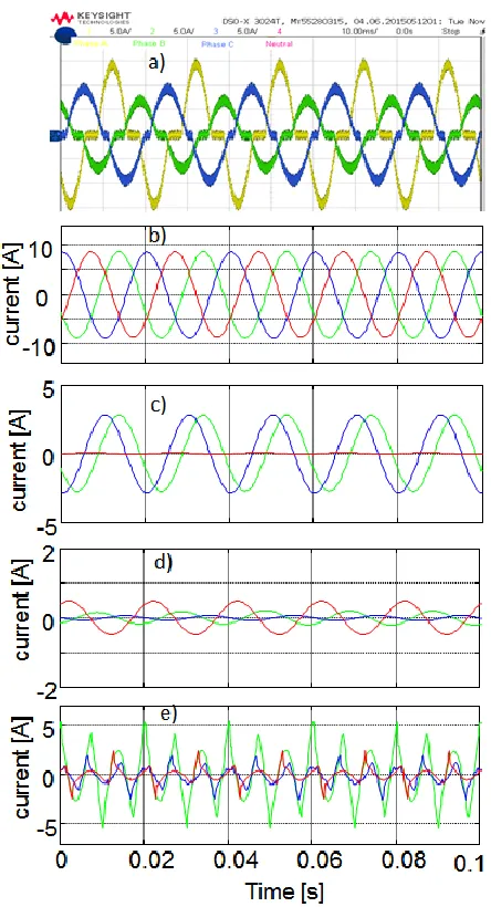
Fig. 6. Fig. 13(a) shows a distorted and unbalanced load-current which has been obtained by modifying the crest factor, in each phase, of the Ametek programmable load. For this load the current has been separated into the currents defined by (5-7). This separation has been realised by the DSPACE platform in real time operation. Fig. 13(b) shows the balanced active currents [see (5)]. As mentioned before, this current is supplied by the 4-leg power source (as shown in Fig. 1). Fig. 13(c) shows the unbalanced active current component [as shown in (7)] which is supplied by the APF. The unbalanced reactive current components are shown in Fig.13(d), finally the void current is shown in Fig. 13(e). For this experimental test the balanced reactive currents have a negligible magnitude and they are not shown in Fig. 13. Finally in Fig. 14 the compensated power supply currents, corresponding to the load currents of Fig. 13(a), are shown. C. Operation of the Proposed 4-leg APF Considering Frequency Variations.
The electrical frequency of a microgrid can be subjected to relatively large variations, e.g. produced by the application of P-f droop control or due to the effect of intermittent generation from renewable sources (see Fig. 7). For the correct operation of the proposed control system, self-tuning resonant controllers have been implemented in this work.
In the experimental implementation discussed in this work, tuning of the resonant controller is achieved by the online calculation of the 𝑘𝑇𝜔𝑗 values [as shown in (13-14)] required by the bilinear transform with frequency pre-warping. In addition a PLL is necessary to estimate the fundamental frequency of the network (as shown in Fig. 3).
To test the performance of the self-tuning resonant control system, the programmable power supply used in this work is controlled using the frequency profile depicted in Fig. 15. Notice that this profile is a piece-wise linearization of that shown in Fig. 7 with some modifications. For instance the duration of the profile has been reduced to 10s and the frequency variation is larger (48Hz to 52Hz). Moreover (as mentioned before) the nominal electrical frequency used in this work is 50Hz instead of the 60Hz utilised for the frequency profile shown in Fig. 7.
Fig. 13. Separation of the load current components using the CPT, a) Load currents. b) Balanced active current. c) Unbalanced active currents. d) Unbalanced reactive currents. e) Void currents.
Fig. 14. Power supply currents corresponding to the experimental test of Fig. 13(a) (10ms/div-5A/div).
The performance of the self-tuning algorithm has been tested considering operation of the system, feeding a load programmed with the current profile depicted in Fig. 13(a) and subjected, during 10s, to the frequency variations shown in
a)
b)
[image:9.612.327.549.48.458.2] [image:9.612.62.286.50.214.2] [image:9.612.330.552.499.632.2]Fig. 15. Frequency profile used in this work.
Fig. 16. Effective (RMS) currents circulating in the programmable power supply. a) Power supply neutral current with and without enabling the active power filter. b) Power supply phase currents considering the active filter enabled.
Fig. 15. Fig. 16 shows the currents in the programmable power supply (captured using the DSPACE data acquisition system). Notice that effective currents are shown because of the problems associated with displaying the instantaneous currents for 10s.
When the power compensator is enabled the neutral current shown in Fig. 16(a) is reduced to a small value produced by the zero-sequence harmonics which are not compensated by the APF. As shown in Fig. 16(b) in the phases of the programmable power supply the effective currents are well balanced. However, because effective currents by themselves cannot be used to demonstrate that the self-tuning algorithm is well tuned, an additional test is proposed and realised in this work. Frequency-adaptive filters have been programmed to process the data captured by the DSPACE platform. The filters are designed to isolate the 5th and 7th harmonics of phase-B in the load and power source currents.
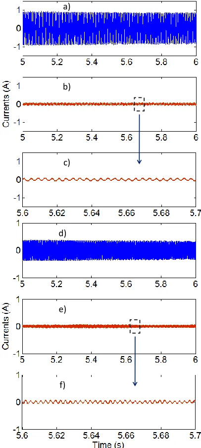
In Figs. 17(a)-(b) the 5th harmonics of the load and power supply currents are depicted between t=5s to t=6s (see Fig. 15). Notice that the frequency is varying between fe=48Hz to fe=51Hz during that period of time. As shown in Fig. 17(a) the amplitude of the 5th harmonic in the load current is about 7.1% of the peak current. Fig. 17(b) shows the 5th harmonic component in the power supply current. Even with the relatively large frequency variation produced in this time period, the harmonic has been compensated and its amplitude is only 0.075A, a reduction of 91% respect to the uncompensated value. An amplified view of the 5th harmonic present in the power supply current is shown in Fig 17(c).
Fig. 17. a) 5th harmonic produced by the load current of Fig. 13(a). b) 5th
harmonic component compensated in the power supply during a relatively fast frequency transient. c) Amplified view of Fig. 17(b). d) 7th harmonic produced
by the load current of Fig. 13(a). e)7th harmonic component compensated in
the power supply during the same frequency transient. f) Amplified view of Fig. 17€.
Using the proposed methodology, the performance of the APF to reject the 7th harmonic has also been evaluated. Again the performance of the APF based self-tuning resonant controllers is excellent, eliminating most of this harmonic from the power supply current as shown in Figs. 17(d)-(f). The amplitude of the 7th harmonic in the load current is about 3.33% of the peak current. However, the amplitude of the 7th harmonic in the power supply current is only 0.05A, a reduction of 87.5% respect to the uncompensated value.
VI. CONCLUSIONS
A new methodology for the control of a 4-leg active power filter has been presented in this paper. The proposed control system is based on the conservative power theory augmented
0 2 4 6 8 10
47 49 51 53
Time [s]
Freq
u
e
n
cy
[Hz]
Curr
en
ts
(A
)
Time (s)
Time (s)
a)b)
APF disabled
APF enabled
b)
a)
b)
c)
d)
e)
[image:10.612.330.533.53.504.2]with a PI and seven self-tuning resonant controllers in each phase. The compensation is achieved by regulating the positive, negative and zero sequence voltages modulated by a 4-leg voltage source converter.
The performance of the proposed control system has been tested considering the operating conditions of a microgrid located in northern Canada. Using per-unit analysis the current and voltages have been referred to values which could be handled by the prototype implemented at the University of Chile. To evaluate the performance of the control system, balanced and unbalanced loads of linear/non-linear nature, considering fixed/variable frequency operation have been applied at the PCC. In all the cases the performance achieved by the proposed 4-leg APF has been excellent.
The advantages of the CPT, as a new power theory for applications such as microgrids where strong distortion and imbalances could be present, have also been demonstrated in this work.
VII REFERENCES
[1] C. Ahumada, R. Cárdenas, D. Sáez y J. M. Guerrero, "Secondary Control Strategies for Frequency Restoration in Islanded Microgrids With Consideration of Communication Delays", IEEE Transactions on Smart Grid, Vol. 7, Nr. 3, pp. 1430-1441, May 2016.
[2] K. Strunz, E. Abbasi y D. N. Huu, “DC Microgrid for Wind and Solar Power Integration,” IEEE Journal of Emerging and Selected Topics in Power Electronics, vol. 2, nº 1, pp. 115-126, 2014.
[3] Y. Huang, X. Yuan, J. Hu, . P. Zhou y D. Wang, “DC-Bus Voltage Control Stability Affected by AC-Bus Voltage Control in VSCs Connected to Weak AC Grids,” IEEE Journal of Emerging and Selected Topics in Power Electronics , vol. 4, nº 2, pp. 445 - 458, 2016.
[4] R.H.Lasseter, “MicroGrids,” Power Engineering Society Winter Meeting, 2002. IEEE, 2002.
[5] M. Hamzeh, S. Emamian, H. Karimi y J. Mahseredjian, “Robust Control of an Islanded Microgrid Under Unbalanced and Nonlinear Load Conditions,” IEEE Journal of Emerging and Selected Topics in Power Electronics, vol. 4, nº 2, pp. 512 - 520, 2016.
[6] Y. Li, D. M. Vilathgamuwa y P. C. Loh, “Microgrid Power Quality Enhancement Using a Three-Phase Four-Wire Grid-Interfacing Compensator,” IEEE Transactions on Industry Applications, vol. 41, nº 6, pp. 1707-1719, 2005.
[7] Y. Yang, K. Zhou y . F. Blaabjerg, “Current Harmonics From Single-Phase Grid-Connected Inverters—Examination and Suppression,” IEEE Journal of Emerging and Selected Topics in Power Electronics , vol. 4, nº 1, pp. 221 - 233, 2016.
[8] S. P. Oe, E. Christopher, M. Sumner, S. Pholboon, M. Johnson y S. A. Norman, “Microgrid Unbalance Compensator – Mitigating the negative effects of unbalanced microgrid operation,” de 4th IEEE PES Innovative Smart Grid Technologies Europe (ISGT Europe), Copenhagen, 2013. [9] D. Sreenivasarao, P. Agarwal y B. Das, “Neutral current compensation in three-phase, four-wire systems: A review,” Electric Power Systems Research, nº 86, p. 170– 180, 2012.
[10] E. Nasr-Azadani, C. Cañizares, D. Olivares y K. Bhattacharya, “Stability Analysis of Unbalanced Distribution Systems With Synchronous Machine and DFIG Based Distributed Generators,” IEEE Transactions on Smart Grid, vol. 5, pp. 2326 - 2338, 2014.
[11] R. H. Salim, R. A. Ramos y N. G. Bretas, “Analysis of the Small Signal Dynamic Performance of Synchronous Generators under Unbalanced Operating Conditions,” de Power and Energy Society General Meeting, 2010 IEEE, Minneapolis, MN, 2010.
[12] J.-C. Wu, H.-L. Jou, K.-D. Wu y H.-H. Hsiao, “Three-phase four-wire hybrid power filter using a smaller power converter,” Electric Power Systems Research, nº 87, p. 13– 21, 2012.
[13] H. Yoshida y K. Wada, “Third-Harmonic Current Suppression for Power Distribution Systems Under Unbalanced Installation of DG Units,”
IEEE Transactions on Industrial Electronics, vol. 62, nº 9, pp. 5578-5585, 2015.
[14] D. Kumar y F. Zare, “Harmonic Analysis of Grid Connected Power Electronic Systems in Low Voltage Distribution Networks,” IEEE Journal of Emerging and Selected Topics in Power Electronics , vol. 4, nº 1, pp. 70 - 79, 2016.
[15] T.-L. Lee y P.-T. Cheng, “Design of a New Cooperative Harmonic Filtering Strategy for Distributed Generation Interface Converters in an Islanding Network,” IEEE Transactions on Power Electronics, vol. 22, nº 5, pp. 1919-1927, 2007.
[16] J. He, Y. Wei Li y M. Shirajum Munir, “A Flexible Harmonic Control Approach Through Voltage-Controlled DG–Grid Interfacing Converters,” IEEE Transactions on Industrial Electronics, vol. 59, nº 1, pp. 444-455, 2012. [17] M. Savaghebi, A. Jalilian, J. C. Vasquez y J. M. Guerrero, “Autonomous Voltage Unbalance Compensation in an Islanded Droop-Controlled Microgrid,” IEEE Transactions on Industrial Electronics, vol. 60, nº 4, pp. 1390-1402, 2013.
[18] G.-H. Kim, C. Hwang, J.-H. Jeon, J.-B. Ahn y E.-S. Kim, “A novel three-phase four-leg inverter based load unbalance compensator for stand-alone microgrid,” Electrical Power and Energy Systems, nº 65, p. 70–75, 2015.
[19] L. S. Czarnecki, “On some misinterpretations of the instantaneous reactive power p-q theory,” IEEE Transactions on Power Electronics, vol. 19, nº 3, pp. 828 - 836, 2004.
[20] L. S. Czarnecki, “Effect of Supply Voltage Harmonics on IRP-Based Switching Compensator Control,” IEEE Transactions on Power Electronics, vol. 24, nº 2, pp. 483-488, 2009.
[21] D. I. Brandao, H. K. Morales Paredes, A. Costabeber y F. P. Marafão, “Flexible active compensation based on load conformity factors applied to non-sinusoidal and asymmetrical voltage conditions,” IET Power Electronics, vol. 9, pp. 356-364, 2016.
[22] A. Lidozzi, C. Ji, L. Sodero, P. Zanchetta y F. Crescimbin, “Resonant– Repetitive Combined Control for Stand-Alone Power Supply Units,” IEEE Transactions on Industry Applications, vol. 51, nº 6, pp. 4653-4663, 2015. [23] P. Tenti y H. K. Morales Paredes, “Accountability in Smart Microgrids Based on Conservative Power Theory,” IEEE Transactions on Instrumentation and Measurement, vol. 60, nº 9, pp. 3058-3069, 2011.
[24] P. Tenti, H. K. Morales Paredes y P. Mattavelli, “Conservative Power Theory, a Framework to Approach Control and Accountability Issues in Smart Microgrids,” IEEE Transactions on Power Electronics , vol. 26, pp. 664-673, 2011.
[25] P. Tenti, A. Costabeber, P. Mattavelli, F. Pinhabel Marafão y H. K. M. Paredes, “Load Characterization and Revenue Metering Under Non-Sinusoidal and Asymmetrical Operation,” IEEE Transactions on Instrumentation and Measurement, vol. 63, nº 2, pp. 422-431, 2014. [26] A. G. Yepes, F. D. Freijedo, J. Doval-Gandoy, Ó. López, J. Malvar y . P. Fernandez-Comesaña, “Effects of Discretization Methods on the Performance of Resonant Controllers,” IEEE Transactions on Power Electronics, vol. 25, nº 7, pp. 1692-1712, 2010.
[27] Z. Lin, S. Huang y S. Wan, “A Novel Control Scheme for T-Type Three-Level SSG Converters Using Adaptive PR Controller with a Variable Frequency Resonant PLL,” Journal of Power Electronics, vol. 16, nº 3, pp. 1176-1189, May 2016.
[28] F. P. Marafão, D. . I. Brandão, F. A. Serrão Gonçalves y H. . K. Morales Paredes, “Decoupled Reference Generator for Shunt Active Filters Using the Conservative Power Theory,” J Control Autom Electr Syst, p. 522– 534, 2013.
[29] T. S.Haugan y E. Tedeschi, “Active power filtering under non-ideal voltage conditions using the conservative power theory,” de IEEE 13th Brazilian Power Electronics Conference and 1st Southern Power Electronics Conference (COBEP/SPEC), Fortaleza, 2015.
[30] R. Pena, R. Cardenas, J. Proboste, G. Asher y J. Clare, “Sensorless Control of Doubly-Fed Induction Generators Using a Rotor-Current-Based MRAS Observer,” IEEE Transactions on Industrial Electronics, vol. 55, nº 1, pp. 330-339, 2008.
[31] H. Akagi, E. Watanabe y M. Aredes, Instantaneous Power Theory and Applications to Power Conditioning, IEEE Press, 2007.
[33] R. Cardenas, C. Juri, R. Pena, J. Clare y P. . Wheeler, “Analysis and Experimental Validation of Control Systems for Four-Leg Matrix Converter Applications,” IEEE Transactions on Industrial Electronics, vol. 59, nº 1, pp. 141-153, 2012.
[34] A. G. Yepes, F. D. Freijedo, O. Lopez y J. Doval-Gandoy, “Analysis and design of resonant current controllers for voltage-source converters by means of Nyquist diagrams and sensitivity function,” IEEE Transactions on Industrial Electronics, vol. 58, nº 11, pp. 5231-5250, 2011.
[35] A. Rodríguez, C. Girón, M. Rizo, V. Sáez, E. Bueno y F. J. Rodríguez, “Comparison of current controllers based on repetitive-based control and second order generalized integrators for active power filters,” de Proc. 35th IEEE Ind. Electron. Soc. (IECON’09), Porto, Portugal, 2009.
[36] S. P. Oe, Power Quality Improvement of Microgrids, Nottingham: Ph.D Thesis University of Nottingham, 2014.
[37] J.-H. Kim y S.-K. Sul, “A carrier-based PWM method for three-phase four-leg voltage source converters,” IEEE Transactions on Power Electronics, vol. 19, pp. 66 - 75, 2004.
[38] G. Holmes y L. , Pulse Width Modulation for Power Converters: Principles and Practice, p. 744: Wiley-IEEE Press, 2003.
Claudio Burgos Mellado was born in Cunco, Chile. He received the B.Sc. and M.Sc. degrees in electrical engineering from the University of Chile, Santiago, in 2012 and 2013, respectively. He is currently a Ph.D student in the double-award Ph.D programme in Electrical Engineering (U. of Chile-U. of Nottingham UK). His current interests include battery energy storage systems, electrical vehicle technologies, power electronics, microgrids and power quality.
Carlos Hernández Carimán was born in Panguipulli, Chile. He received the B.Sc. degree in electronic engineering from the University of Concepción, Concepción, Chile, in 2013 and the M.Sc. degree in electrical engineering from the University of Chile, Santiago, Chile, in 2016. His research fields include 4-leg active filter, power electronics, microgrids and renewable energy systems.
Roberto Cárdenas (S'95-M'97-SM'07) was born in Punta Arenas, Chile. He received his B.S. degree from the University of Magallanes, Chile, in 1988 and his Msc. and Ph.D degrees from the University of Nottingham in 1992 and 1996 respectively. From 1989-1991 and 1996-2008 he was a lecturer in the University of Magallanes Chile. From 1991 to 1996 he was with the Power Electronics Machines and Control Group (PEMC group), University of Nottingham, United Kingdom. From 2009-2011 he was with the Electrical Engineering Department, University of Santiago. He is currently a full professor of power electronics and drives in the Electrical Engineering Department, University of Chile, Chile. His main interests are in control of electrical machines, variable speed drives and renewable energy systems.
Doris Sáez (S’93–M’96–SM’05) was born in Panguipulli, Chile. She received the M.Sc. and Ph.D. degrees in electrical engineering from the Pontificia Universidad Católica de Chile, Santiago, Chile, in 1995 and 2000, respectively. She is currently an associate professor with the Electrical Engineering Department, University of Chile, Chile. She has co-authored the books Hybrid Predictive Control for Dynamic Transport Problems (SpringerVerlag, 2013) and Optimization of Industrial Processes at Supervisory Level: Application to Control of Thermal Power Plants (Springer-Verlag, 2002). Her research interests include predictive control, fuzzy control design, fuzzy identification, control of power generation plants, and control of transport systems. Dr. Sáez is an Associate Editor of the IEEE TRANSACTIONS ON FUZZY SYSTEMS.
Mark Sumner (SM 2005) received the B.Eng degree in Electrical and Electronic Engineering from Leeds University in 1986 and then worked for Rolls Royce Ltd in Ansty, UK. Moving to the University of Nottingham, he completed his PhD in induction motor drives in 1990, and after working as a research assistant, was appointed Lecturer in October 1992. He is now Professor of Electrical Energy Systems. His research interests cover control of power electronic systems including sensorless motor drives, diagnostics and prognostics for drive systems, power electronics for enhanced power quality and novel power system fault location strategies.
Alessandro Costabeber (S’09–M’13) received the Degree with honours in Electronic Engineering from the University of Padova, Padova, Italy, in 2008 and the Ph.D. in Information Engineering from the same university in 2012, on energy efficient architectures and control techniques for the development of future residential microgrids. In the same year he started a two-year research fellowship with the same university. In 2014 he joined the PEMC group, Department of Electrical and Electronic Engineering, University of Nottingham, Nottingham, UK as Lecturer in Power Electronics. His current research interests include HVDC converters topologies, high power density converters for aerospace applications, control solutions and stability analysis of AC and DC microgrids, control and modelling of power converters, power electronics and control for distributed and renewable energy sources. Dr. Costabeber received the IEEE Joseph John Suozzi INTELEC Fellowship Award in Power Electronics in 2011.