ISSN Online: 2327-6053 ISSN Print: 2327-6045
DOI: 10.4236/msce.2019.71002 Jan. 22, 2019 10 Journal of Materials Science and Chemical Engineering
Research and Application of the Novel Deep
Plugging Method in the Oilfield
Juan Zhao
1,2,3, Hongfu Fan
1,2,3*, Long Liu
1,2,3, Yi Jia
1,2,31School of Energy Resources, China University of Geosciences (Beijing), Beijing, China
2Key Laboratory of Marine Reservoir Evolution and Hydrocarbon Enrichment Mechanism, Ministry of Education,
Beijing, China
3Beijing Key Laboratory of Unconventional Natural Gas Geological Evaluation and Development Engineering,
Beijing, China
Abstract
In long-term water drive reservoir, small dose and short radius profile control cannot meet the needs, so deep profile control and flooding are needed. Dur-ing the placement and processDur-ing of conventional deep profile control and flooding agent, the zone classification formed by the changes of pressure field and fluid field are not taken into account. In order to better develop these re-servoirs, we proposed a novel deep profile control method, that is, the iso-pressure drop gradient progressive deep profile control method. The key features of the method include: 1) the method took into account the reservoir pressure distribution; 2) it proposed a novel standard to divide the orders of zone; 3) the method has been successfully applied in 4 wells in China Oilfield. The method divided the formation into near wellbore zone, well-far zone and deep zone according to the drawdown curve. As each zone of the pressure gradient is different and therefore require different intensity of slug. Then de-sign the agent slugs according to iso-pressure drop gradient rule, and the breakthrough pressure gradient of agent is equal to the formation pressure gradient, and it achieved the fluid diversion of whole course by combining the different intensity of blocking agent. The method was applied successfully in 2 wells in China Oilfield from May to November in 2008. The method can smartly improve the sweep efficiency, and field test shows that it can play a very good efficiency of reducing water and increasing oil production. This method is becoming more of a concern in the oilfield develop.
Keywords
Deep Profile Control, Heterogeneity, Pressure Distribution, Iso-Pressure Drop Gradient
How to cite this paper: Zhao, J., Fan, H.F., Liu, L. and Jia, Y. (2019) Research and Application of the Novel Deep Plugging Method in the Oilfield. Journal of Materials Science and Chemical Engineering, 7, 10-19.
https://doi.org/10.4236/msce.2019.71002
Received: December 18, 2018 Accepted: January 19, 2019 Published: January 22, 2019
Copyright © 2019 by author(s) and Scientific Research Publishing Inc. This work is licensed under the Creative Commons Attribution-NonCommercial International License (CC BY-NC 4.0). http://creativecommons.org/licenses/by-nc/4.0/
DOI: 10.4236/msce.2019.71002 11 Journal of Materials Science and Chemical Engineering
[2]. Excess water production is a frequent problem that occurs in mature reser-voirs as a result of long time water-flooding. Such excess water production usually results in increased environmental concerns, increased levels of corro-sion and scale and ultimately leads to early shut-in of wells that still contain sig-nificant volumes of hydrocarbons [3][4][5]. Currently, polymer flooding tech-nology [6]-[13] is the proven tertiary oil recovery technique all over the world, however, the polymer solution readily crossflow [14][15][16] in thief zone. The crossflow causes an invalid injection [17] [18] [19]. For long-term water drive reservoir, high capacity channel well developed, the small dose and short radius profile control cannot meet the needs, so we need deep flooding [20][21]. The crosslinked polymer gel is the most widely used chemicals for conformance con-trol, especially for in-depth fluid diversion [22] Extensive using of cross linked polymer [23][24] solution in high permeability oilfields can obtain good results. The existing deep flooding technology adopts multistage combination method to design the slugs, but not combine with the distribution of current pressure field and fluid field, mainly due to hardly gain the distribution of current dynamic pressure field and fluid field, and lack of means to divide steps, simultaneously lack the blocking agent which can migrate into the deep formation. Whether the profile control agent can stay in the formation depends on the formation pres-sure gradient. When the prespres-sure gradient is greater than the strength of the plugging agent, plugging agent can’t stay in the stratum and will be pushed into the deep part of the stratum. Optimizing and placing the blocking agent in dif-ferent positions in the stratum in order to achieve progressive fluid diversion, already become a very promising direction [25]. The progressive deep flooding method is suit for the current stage of development, can further tap potential of remaining oil.
The paper divided layer according to the drawdown curve, and the method
DOI: 10.4236/msce.2019.71002 12 Journal of Materials Science and Chemical Engineering
Figure 1. The schematic diagram of Stratigraphic division.
the sweep efficiency, and field test shows that the method can play a very good efficiency of reduce water and increase oil production.
2. Materials and Method
2.1. Experiment Materials
We use polymer gel as the plugging agent. The chemicals include HPAM (mol wt about 2220 × 104, solid content about 88%, degree of hydrolysis about 27%), chromium crosslinking agent, NaCl (analytical reagent, Laiyang Chemical). For the experimental water, we used the produced water according to the current polymer flooding situation of the oilfield, and after water quality analysis, its composition is shown in Table 1, and other materials shown in Table 2.
2.2. Experiment Methods
2.2.1. Determination of Breakthrough Pressure Gradient
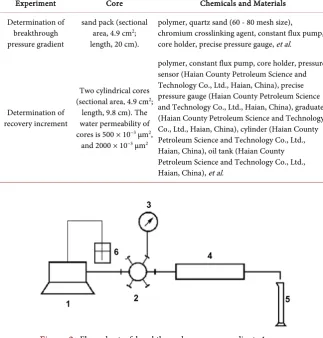
The temperature is set at 65˚C, which is under the reservoir conditions, while the injection rate is 0.5 mL/min. Use breakthrough pressure gradient to evaluate the shut off capacity of plugging agent, and the flow schematic drawing follows
Figure 2. The injection rate is 0.5 ml/min. Test procedure: 1) Fill the pack with sand and weigh the dry weight; saturate it with water and measure the wet weight and calculate the pore volume; 2) Flood by water and measure the per-meability after the pressure is stable; 3) Inject gel solution (add the crosslinking agent solution into the polymer solution), as much as one time pore volume, wait for gelling; 4) Water drive and record the pressure when the water starts flowing out, account the breakthrough pressure gradient.
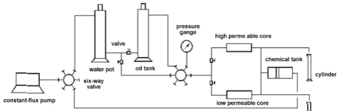
2.2.2. Determination of Recovery Increment
DOI: 10.4236/msce.2019.71002 13 Journal of Materials Science and Chemical Engineering
Experiment Core Chemicals and Materials
Determination of breakthrough pressure gradient
sand pack (sectional area, 4.9 cm2;
length, 20 cm).
polymer, quartz sand (60 - 80 mesh size), chromium crosslinking agent, constant flux pump, core holder, precise pressure gauge, et al.
Determination of recovery increment
Two cylindrical cores (sectional area, 4.9 cm2;
length, 9.8 cm). The water permeability of cores is 500 × 10−3 μm2,
and 2000 × 10−3 μm2
polymer, constant flux pump, core holder, pressure sensor (Haian County Petroleum Science and Technology Co., Ltd., Haian, China), precise pressure gauge (Haian County Petroleum Science and Technology Co., Ltd., Haian, China), graduate (Haian County Petroleum Science and Technology Co., Ltd., Haian, China), cylinder (Haian County Petroleum Science and Technology Co., Ltd., Haian, China), oil tank (Haian County Petroleum Science and Technology Co., Ltd., Haian, China), et al.
Figure 2. Flow chart of breakthrough pressure gradient. 1—cons- tant-flux pump; 2—six-way valve; 3—precision pressure gauge; 4— sand pack ; 5—measuring cylinder; 6—beaker.
[image:4.595.207.537.159.523.2] [image:4.595.208.532.168.507.2]DOI: 10.4236/msce.2019.71002 14 Journal of Materials Science and Chemical Engineering
Figure 3. The recovery increment measuring device of double core model.
3. Results and Discussion
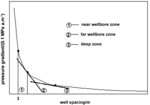
Compute the pressure gradient curve from the water well to oil well by numeri-cal stimulation, and divide zones according to drawdown curve.
3.1. Divided the Profile Control Zone
The drop curve of the target well is shown in Figure 4. The stratum is divided by the tangent line of the formation pressure gradient curve, and the tangent point corresponds to the boundary point near the well area, the far well zone and the deep stratum. Follows as Figure 3, the near wellbore zone 3 - 8 m; far wellbore zone 8 - 20 m; deep zone ≥ 20 m, in order to prevent shaft plugging, no plugging agent is set within 3 meters.
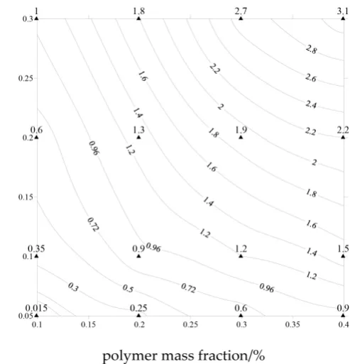
3.2. Determination of Breakthrough Pressure Gradient Isogram
Determine the breakthrough pressure gradient at different formulations of plug-ging agents. Mark the breakthrough pressure gradient on the map area, and connect the equivalent point, then draw the breakthrough pressure gradient iso-gram, follows as Figure 5. The data unit is MPa/m, and with the increase of reactant concentration, the breakthrough pressure gradient increases in Figure 5, and the range is 0.015 MPa/m - 3.1 MPa/m.3.3. Slugs Combination Optimization Design
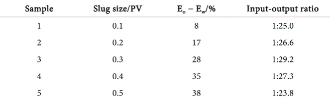
3.3.1. Optimization of the Slug CombinationDetermine the recovery increment of blocking agent with different volume, cal-culate the input-output ratio, and optimize the combination. Hypothetic the oil price is Ұ2500 per ton, the blocking agent is Ұ80 per square, and the other in-vestment is twice the cost of blocking agent. Table 3 presents the Effect of slug size on input-output ratio, when the injection rate is 0.3Vp(thief zone), the in-put-output ratio attain smallest, have better economic benefit, and cost is oppo-site lower.
3.3.2. Optimization Model
According to geological reservoir data, the permeability of the thief zone is 2 μm2, the porosity is 30%, thickness is h, well spacing R
DOI: 10.4236/msce.2019.71002 15 Journal of Materials Science and Chemical Engineering
(
2- 32)
(
2- 32)
0.3e
r h R h
[image:6.595.223.520.65.424.2]π × π × = , r = 55 (m).
Figure 4. The pressure gradient curve of injection well.
[image:6.595.261.508.448.705.2]DOI: 10.4236/msce.2019.71002 16 Journal of Materials Science and Chemical Engineering
Table 3. Effect of slug size on input-output ratio.
Sample Slug size/PV Eo − Ew/% Input-output ratio
1 0.1 8 1:25.0
2 0.2 17 1:26.6
3 0.3 28 1:29.2
4 0.4 35 1:27.3
5 0.5 38 1:23.8
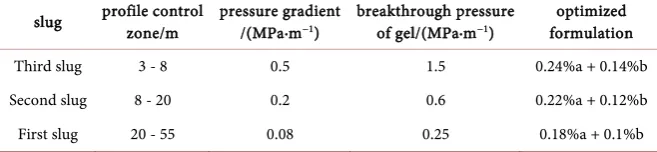
According to the formation conditions above mentioned, the entrance depth is 55 m, so the profile control range is 3 - 55 m. The blocking agent is divided into three slugs as follows in Figure 6. In order to ensure the agent can effec-tively plug formation, choose the maximum pressure gradient of each slug as the blocking agent required strength, namely the breakthrough pressure gradient of third slug is the pressure gradient when well spacing is 3 m, the breakthrough pressure gradient of second slug is the pressure gradient when well spacing is 8 m, and the breakthrough pressure gradient of first slug is the pressure gradient when well spacing is 20 m.
In the actual displacing process, the strength loss of plugging agent is affected by perforation, ground flow, well head, well spacing and so on, and the perfora-tion loss attains 40%. Considering various factors, improve gel strength to 3 times of theoretical strength. The breakthrough pressure gradient of near well-bore zone is 1.4 MPa·m−1, the breakthrough pressure gradient of far wellbore zone is 0.6 MPa·m−1, and the breakthrough pressure gradient of deep zone is 0.2 MPa·m−1. Select a series of formulation from the breakthrough pressure gradient isogram of gel, and optimize the synergy follows as Table 4. The best combina-tion is: the first slug is 0.18% polymer and 0.10% crosslinker, the second slug is 0.22% polymer and 0.12% crosslinker, the third slug is 0.24% polymer and 0.14% crosslinker.
4. Conclusions
1) The iso-pressure drop gradient progressive deep profile control method took into account the reservoir pressure distribution. Classify zones according to drawdown curve, and divide the formation into near wellbore zone, well-far zone and deep zone.
2) Draw the breakthrough pressure gradient isogram of gel, the data show that with the increase of reactant concentration, the breakthrough pressure gradient increases, and the range is 0.015 MPa/m - 3.1 MPa/m.
DOI: 10.4236/msce.2019.71002 17 Journal of Materials Science and Chemical Engineering
Figure 6. The schematic diagram of gel slug.
Table 4. The slug optimization of gel.
slug profile control zone/m pressure gradient /(MPa∙m−1) breakthrough pressure of gel/(MPa∙m−1) formulation optimized
Third slug 3 - 8 0.5 1.5 0.24%a + 0.14%b
Second slug 8 - 20 0.2 0.6 0.22%a + 0.12%b
First slug 20 - 55 0.08 0.25 0.18%a + 0.1%b
(a—ploymer, b—crosslinker).
polymer and 0.12% crosslinker, the third slug is 0.24% polymer and 0.14% cros-slinker.
Conflicts of Interest
The authors declare no conflict of interest.
References
[1] Liu, Y., Zhu, M., Liu, X., et al. (2006) Hans-JuergenHigh Clay Content Nano- Composite Hydrogels with Surprising Mechanical Strength and Interesting Des- welling Kinetics. Polymer, 47, 1-5. https://doi.org/10.1016/j.polymer.2005.11.030 [2] Alhuraishawy, A.K., Bai, B., Imqam, A., et al. (2018) Experimental Study of
Combining Low Salinity Water Flooding and Preformed Particle Gel to Enhance Oil Recovery for Fractured Carbonate Reservoirs. Fuel, 214, 342-350.
https://doi.org/10.1016/j.fuel.2017.10.060
[3] Hua, Z., Lin, M., Dong, Z., et al. (2014) Study of Deep Profile Control and Oil Dis-placement Technologies with Nanoscale Polymer Microspheres. Journal of Colloid & Interface Science, 424, 67-74. https://doi.org/10.1016/j.jcis.2014.03.019
[4] Kotlar, H.K., Olav Selle, S., et al. (2007) Enhanced Oil Recovery by COMB-Flow: Polymer Floods Revitalized.
[5] Du, Y. and Guan, L. (2004) Field-Scale Polymer Flooding: Lessons Learnt and Ex-periences Gained during Past 40 Years.
[6] Wang, Q.M., Liao, G.Z., Niu, J.G., et al. (1999) Theoretical Research on Polymer Flooding. Petroleum Geology & Oilfield Development in Daqing, 18, 1-5.
[image:8.595.207.536.259.335.2]DOI: 10.4236/msce.2019.71002 18 Journal of Materials Science and Chemical Engineering https://doi.org/10.2118/124798-MS
[8] Seright, R.S. (2016) How Much Polymer Should Be Injected During a Polymer Flood? Review of Previous and Current Practices. SPE Journal, 1-18
[9] Huang, B., Zhang, W., Xu, R., et al. (2017) A Study on the Matching Relationship of Polymer Molecular Weight and Reservoir Permeability in ASP Flooding for Duanxi Reservoirs in Daqing Oil Field. Energies, 10, 1-10.
https://doi.org/10.3390/en10070951
[10] Alsofi, A.M. and Blunt, M.J. (2014) Polymer Flooding Design and Optimization under Economic Uncertainty. Journal of Petroleum Science and Engineering, 124, 46-59. https://doi.org/10.1016/j.petrol.2014.10.014
[11] Zhu, D., Wei, L., Wang, B., et al. (2014) Aqueous Hybrids of Silica Nanoparticles and Hydrophobically Associating Hydrolyzed Polyacrylamide Used for EOR in High-Temperature and High-Salinity Reservoirs. Energies, 7, 3858-3871.
https://doi.org/10.3390/en7063858
[12] Liu, S., Shen, A., Qiu, F., et al. (2017) Matching Relationship and Alternating Injec-tion for Polymer Flooding in Heterogeneous FormaInjec-tions: A Laboratory Case Study of Daqing Oilfield. Energies, 10, 1018. https://doi.org/10.3390/en10071018
[13] Liu, B., Sun, X.Z., Wang, K., et al. (2007) Flooding by High-Concentration Polymer Doubled Oil Recovery of Common Polymer on Field Test with 20% Closed to the Result of Laboratory Test in Daqing.
[14] Azarshin, S., Moghadasi, J., Aboosadi, Z.A., et al. (2017) Surface Functionalization of Silica Nanoparticles to Improve the Performance of Water Flooding in Oil Wet Reservoirs. Energy Exploration & Exploitation, 35, 685-697.
https://doi.org/10.1177/0144598717716281
[15] Abedi, B., Ghazanfari, M. and Kharrat, R. (2012) Experimental Study of Polymer Flooding in Fractured Systems Using Five-Spot Glass Micromodel: The Role of Fracture Geometrical Properties. Energy Exploration & Exploitation, 30, 689-706. https://doi.org/10.1260/0144-5987.30.5.689
[16] Sun, P.X. (2012) A Fuzzy Method to Judge Water Passages with Ineffective Injec-tion-Production for Heterogeneous Sandstone Reservoir. Advanced Materials Re-search, 524-527, 1306-1309.
[17] Liu, L., Song, K., Pi, Y., et al. (2010) Notice of Retraction Recognize the Low-Effi- ciency Water Passage in Multilayer Non-Uniform Reservoir with Fuzzy Evaluation. International Conference on Advanced Computer Control, Singapore, 5, 139-141. [18] Paradis, C.J., Dixon, E.R., Lui, L.M., et al. (2018) Improved Method for Estimating
Reaction Rates during Push-Pull Tests. Ground Water.
[19] Zhang, T., Su, L., Liu, J., et al. (2009) Research and Development Trend of Profile Technology on the Deep of Gel. Oil-Gasfield Surface Engineering, 28, 26-27. [20] Wu, J.C., Wang, Z., Zhao, Y., et al. (2013) Study on the Evaluation Method of Deep
Profile Control and Flooding Effect. Advanced Materials Research, 712-715, 773-
777.https://doi.org/10.4028/www.scientific.net/AMR.712-715.773
[21] Mattias, S. and Einar, N. (2013) Methods and Systems for Streamer Depth Profile Control. American Patent, US8573050.
[22] Liu, Y., Bai, B. and Shuler, P.J. (2006) Application and Development of Chemi-cal-Based Conformance Control Treatments in China Oil Fields. SPE 99641. [23] Li, M., Wang, A., Yu, X., et al. (2007) The Flowing Diversion Mechanism of Linked