MASTER THESIS
DESIGN AND
CONSTRUCTION OF A
SETUP THAT REPRESENTS
THE BEHAVIOR OF A
HELICOPTER ROTOR
BLADE SYSTEM
J. Wolters
FACULTY OF ENGINEERING TECHNOLOGY APPLIED MECHANICS
EXAMINATION COMMITTEE
prof.dr.ir. A. de Boer dr.ir. R. Loendersloot dr.ir. W.B.J. Hakvoort
MASTER THESIS
DESIGN AND CONSTRUCTION OF A SETUP THAT REPRESENTS THE
BEHAVIOR OF A HELICOPTER ROTOR BLADE SYSTEM
Student
Full name Joris Wolters
Student number s0166847
University
Institution University of Twente
Faculty Engineering Technology
Research group Applied Mechanics
Chair Structural Dynamics & Acoustics
Supervisors dr.ir. R. Loendersloot and A. Sanchez Ramirez MSc.
Graduation professor prof.dr.ir. A. de Boer
Preface
This report presents the work that has been performed during my master’s assignment. This assignment was done at the department of Applied mechanics at the University of Twente. For this assignment, I designed and built a demonstrator that represents the behavior of a helicopter Rotor Blade System. It has been a memorable year with several ups and downs during the assignment. With finishing this assignment, my career as a Mechanical Engineering student also comes to an end. Looking back on my life as a student, I can conclude that it has been an amazing time and that I’ve had lots of unforgettable experiences during my student life. Leaving my parent’s house to live in Enschede, the many group projects during the bachelor’s phase and the study tour to Dubai and Indonesia in 2010 are some of the highlights of the bachelor phase. For my master phase, my internship at KND in Cape Town in 2013 has been an absolute highlight. It really opened my eyes for the possibility of working abroad and besides that, it was a wonderful time in an amazing city and country.
Summary
Rotor Blade Systems (RBS) like helicopters or wind turbines are complex mechanical structures that make use of flexible rotating blades to fulfill their functions. When an RBS is in operation, the blades will display several types of deformations that are highly dependent on the flight (helicopter) or weather (wind turbine) conditions. With the rotor and blades usually being the main source of vibrations in RBS, it would be favorable to monitor the behavior of the system by monitoring directly on the rotor and blades. On-blade monitoring is however not that advanced in RBS.
Previous performed experimental research regarding RBS was reviewed to investigate the added value of on-blade monitoring in systems like these. The reviewed experiments are presented in a table that shortly describes the characteristics and the goals of the experiments. Furthermore, each of the experiments was classified on the basis of the number of Degrees Of Freedom (DOFs) that were being excited and monitored. It turned out that not a lot of experimental research was performed where multiple DOFs were being excited and monitored.
This thesis focuses on the design and construction of a functional setup that represents the behavior of a helicopter RBS. This demonstrator can be used to test different strategies for on-blade monitoring in RBS. Investigation of the characteristics of RBS learned that the behavior of these systems is complex. Therefore, the complexity of the behavior is reduced for the design of the demonstrator. How this complexity was reduced is described after defining the behavior of the RBS. On the basis of the desired behavior of the demonstrator, the design requirements are stated. An important requirement was that the ratio between first mode frequencies of the setup correspond with those of a real helicopter. Another important requirement was that the demonstrator could be used to test different blade profiles on it.
The demonstrator that was eventually built contains of a single hanging, for which cyclic pitch (change of the blade angle over the radial axis) and flap (up and down movement of the blade) are excited. By exciting two DOFs, the demonstrator can potentially fill a gap in the table with the classified experiments; i.e. by exciting and monitoring multiple DOFs. Cyclic pitch is actuated at constant frequency by a Voice Coil Motor (VCM), while flap is actuated with a broadband frequency signal by a shaker. Furthermore, the demonstrator contains hinges for all DOFs. The flap and lag hinges have a rotational stiffness, generated by torsion springs that are connected on the outer side of the hinges. These rotational stiffnesses in the hinges are needed to be able to realize the required mode frequencies. By keeping the torsion springs outside the hinges, it is possible to replace the springs if other stiffnesses are required when different blade profiles are tested.
vibrations in the system, which is highly unfavorable when on-blade monitoring strategies will be tested with the demonstrator.
Samenvatting
Rotor-blad-systemen (RBS), zoals bijvoorbeeld helikopters of windturbines, zijn complexe mechanische systemen die gebruik maken van flexibele roterende bladen om aan hun functie te voldoen. Wanneer een RBS in operatie is, zullen de bladen verschillende vervormingen laten zien, welke afhankelijk zijn van het type vlucht (helikopter) of het weer (windturbine). Gezien het feit dat de rotor en de bladen vaak de hoofdoorzaak van trillingen in RBS zijn, zou het gewenst zijn om het gedrag van de rotor en de bladen direct te kunnen observeren door het uitvoeren van metingen op het blad en rotor. Het blijkt echter dat het direct op het blad monitoren van RBS nog niet erg geavanceerd is.
Experimenten die met RBS te maken hebben zijn bekeken om de mogelijk toegevoegde waarde van het direct op het blad monitoren in RBS te onderzoeken. De onderzochte experimenten zijn in een tabel weergegeven waarin elk van de onderzoeken kort wordt beschreven middels de eigenschappen en het hoofddoel van de experimenten. Verder zijn de experimenten ingedeeld op basis van het aantal vrijheidsgraden (Degrees Of Freedom, DOFs) welke zijn gemonitord en welke zijn ge¨exciteerd. Het bleek dat er weinig experimenteel onderzoek gedaan is waarin meerdere DOFs zijn ge¨exciteerd en gemonitord.
Dit proefschrift richt zich op het ontwerpen en het bouwen van een opstelling welke het gedrag van een helikopter RBS representeert. Deze opstelling kan worden gebruikt om verschillende meetstrategie¨en voor RBS te testen waarbij er direct op het blad gemonitord wordt. Het blijkt dat het gedrag van RBS complex is, waardoor is besloten om de complexiteit van het gedrag te reduceren voor het ontwerp van de opstelling. In welke mate de complexiteit is gereduceerd zal worden beschreven nadat het gedrag van de RBS is beschreven. Aan de hand van het gewenste gedrag voor de opstelling is een lijst van ontwerpeisen samengesteld. Een belangrijke eis was dat de verhouding tussen de frequenties behorende bij de eerste trillingsvormen van de opstelling gelijk moest zijn aan die van een helikopter. Een andere belangrijke eis was dat de opstelling gebruikt moet kunnen worden om er verschillende bladprofielen mee te testen.
De opstelling die uiteindelijk gebouwd is bestaat uit een hangend blad, waarvoor cyclische pitch (hoekveran-dering van het blade over de radiale as) en flap (op- en neergaande beweging van het blad) ge¨exciteerd kunnen worden. Door twee verschillende DOFs aan te sturen, zou de opstelling in potentie een leeg plekje in de tabel met de ingedeelde experimenten kunnen opvullen; namelijk door meerdere DOFs te exciteren en te monitoren. Cyclische pitch wordt met constante frequentie aangestuurd door een Voice Coil Motor (VCM), terwijl flap met een breedband frequentiesignaal wordt aangestuurd door een shaker. Verder heeft de opstelling scharnieren voor alle DOFs. Van deze scharnieren hebben de flap- en lagscharnieren een rotatiestijfheid, die nodig is om de gewenste frequenties bij de trillingsvormen te realiseren. Deze rotatiestijfheden worden gerealiseerd door torsieveren die aan de buitenkant van de scharnieren aan het systeem worden verbonden. Door ze aan de buitenkant te verbinden, wordt de mogelijkheid om de veren te vervangen opengehouden. Dit zou nodig kunnen zijn als andere stijfheden gewenst zijn wanneer andere bladprofielen gebruikt worden.
ook getest; het aansturen van zowel pitch als flap. Excitatie van pitch door middel van een VCM bleek een aantal problemen op te leveren. Zo was het door de magnetische kern van de actuator onmogelijk om een stabiele evenwichtspositie te vinden. Daarnaast maakten de kern en de spoel contact met elkaar bij elke cyclus, wat ongewenste trillingen in het systeem met zich meebrengt. Dit is zeer ongewenst wanneer er direct op het blad gemeten moet worden.
Nomenclature
This section a list of terms, abbreviations and symbols that are used throughout this report.
Glossary
Accelerometers are sensors that were used during the testing phase fo this assignment and that can measure the acceleration of the point it is subjected to.
ANSYSis a finite element analysis package that is used during the design process.
Demonstratoris the setup that was designed built during this assignment.
Featheringis the twist motion of the blade around the radial axis.
Flappingis the up and down movement of the blade.
Flexureis the flexible element that is used for the actuation of flap in the demonstrator.
Lead-lagging is the forwards and backwards movement of the blade in the plane of rotation. Lead-lagging is referred to as Lead-lagging throughout most of the report.
MATLAB is a technical computing language that is used for the calculations throughout this assign-ment.
Pitchis the rigid twist of the blade around the radial axis.
Shakeris an actuator that is used to excite the flapping movement in the demonstrator.
SolidWorksis a 3D CAD software package that is used to model the design of the demonstrator.
Abbreviations
DOFstands for Degree Of Freedom
EDMstands for Electric Discharge Machining
FBSstands for Function-Behavior-Structure
FRFstands for Frequency Response Function
RBSstands for Rotor Blade System
RMSstands for Root Mean Square
VCMstands for Voice Coile Motor
WSNstands for Wireless Sensor Networks
List of symbols
A is a constant for the calculation of the natural bending frequency of a beam.
A1,2 are the integration constants in the solution forT(t).
B1,2,3,4 are the integration constants in the solution forY(x). Cf is the desired rotational stiffness of the flap hinge. Cg is the gravitational rotational stiffness of a pendulum. CF is the desired rotational stiffness of the flap hinge. CL is the desired rotational stiffness of the lag hinge.
CSF is the torsional stiffness of the torsion spring that is used for the flap hinge.
CSL is the torsional stiffness of the torsion spring that is used for the lag hinge.
E is the Young’s modulus.
f is the rigid body pendulum frequency of a hanging blade.
f(x, t) represents the external forces on a beam at positionxand timet.
ffel,1 is the first elastic flapping frequency of the blade. ffr is the rigid body flapping frequency of the blade.
flr is the rigid body lagging frequency of the blade.
F is the force that the torsion spring legs exert on the demonstrator.
Fmax is the maximum force that is needed for the actuation of pitch. FRM S is the root mean square of the force for the actuation of pitch. g is the gravitational constant.
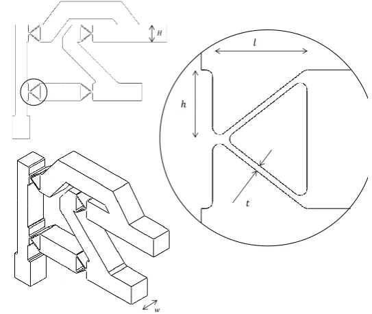
h is a design parameter of the flexure; it represents the leaf height.
dh is the change in distance between the torsion spring legs.
H is a design parameter of the flexure; it represents the beam height.
H is a characteristic of a cross hinge; it represents half the hinge height.
I(x) is the area moment of inertia of a cross section at positionx.
IRM S is the root mean square of the current for the actuation of pitch.
Iy is the mass moment of inertia with respect to the pitch axis of the demonstrator. K is the rotational stiffness of a cross hinge.
K is the rotational stiffness that is used for the derivation of the effect of such a stiffness on the bending frequency.
Kf is the force constant of the VCM.
Kf lap is the rotational stiffness of the flap hinge.
Kh is the rotational stiffness of a single hinge of the flexure. Klag is the rotational stiffness of the lag hinge.
l is a design parameter of the flexure; it represents the hinge length.
l is a characteristic of a cross hinge; it represents the leaf length of a single leaf.
L is the blade length.
LF is the arm that is used to connect the flap torsion spring to the flap hinge. LL is the arm that is used to connect the lag torsion spring to the lag hinge. LSF is the leg length for the torsion spring that is used for flap.
LSL is the leg length for the torsion spring that is used for lag.
m is the mass of the blade.
m is the total moving mass experienced by the VCM.
mef f is the effective mass of the demonstrator experienced by the pitch actuator. MF is the moment around the flap axis.
MS is the torsional moment of the torsion spring. P is the power dissipation for the actuation of pitch.
PC is the continuous power of the VCM. r is the arm at which pitch is actuated.
R is the resistance of the VCM.
t is the time.
t is a design parameter of the flexure; it represents the leaf thickness.
T is the cycle time for the actuation of cyclic pitch.
T(t) is a function of time that is needed to describe the deflection of a bending beam.
w is a design parameter of the flexure; it represents the width of the mechanism.
x determines the position on a beam.
x(t) is the function that describes the positional output of the linear pitch actuator.
˙
xmax is the maximum velocity that is required for the actuation of pitch. ¨
X is the total stroke for the pitch actuator.
y is the deflection of a bending beam.
dy is the deflection of the flexure at a certain load.
Y(x) is a function of displacement that is needed to describe the deflection of a bending beam.
β is a variable that is needed to calculate the natural bending frequency of a beam that has a rotational stiffness at one side.
θ is the rigid body flapping angle of a blade.
θ is the angle change of a hinge of the flexure at a certain load.
dθ is the angle change of the torsion spring for the derivation of the required leg length.
Θ is the angle amplitude for the actuation of pitch.
ρ is the mass density per unit length of a beam.
φ is the angle of the blade for te derivation of the natural bending frequency.
ϕ is a characteristic of a cross hinge; it represents the angle of the leafs.
dϕ is the angle change of the blade for the derivation of the required torsion spring leg length.
ωn is the natural bending frequency of a beam.
Contents
Preface i
Summary iii
Samenvatting v
Nomenclature vii
1 Introduction 1
1.1 Rotor Blade Systems . . . 2
1.2 Assignment objective . . . 5
1.3 Thesis outline . . . 5
2 Literature 7 2.1 RBS . . . 7
2.2 Previous experiments . . . 9
2.3 Classification of experiments . . . 14
2.4 Conclusion of experiments . . . 15
3 Design process 17 3.1 Function . . . 17
3.2 Behavior . . . 17
3.3 Structure . . . 18
3.4 Design requirements . . . 19
3.5 Design procedure . . . 20
3.6 First design decisions . . . 21
3.7 Summary . . . 22
4.2 Blade clamp . . . 24
4.3 Flap hinge . . . 24
4.4 Lag hinge . . . 27
4.5 Pitch hinge . . . 29
4.6 Summary . . . 29
5 Design of actuation and frame 31 5.1 Actuation of flap . . . 31
5.2 Actuation of pitch . . . 35
5.3 Frame . . . 37
6 Experiments 41 6.1 Flexure tests . . . 41
6.2 Demonstrator tests . . . 44
6.3 Blade tests . . . 46
6.4 Pitch . . . 48
6.5 Test conclusions . . . 50
7 Conclusions & Recommendations 51 7.1 Conclusions . . . 51
7.2 Recommendations . . . 52
Bibliography 55 Appendices 57 A Effect of a rotational stiffness 59 B External torsion spring design 63 C ANSYS analysis of the flexure mechanism 67 C.1 Elements . . . 67
C.2 Verification of the model . . . 68
C.3 Adaptations after testing . . . 70
C.4 Recommendations for new flexure design . . . 71
D Mini-shaker data sheet 73
1. Introduction
Rotor Blade Systems (RBS) such as helicopters and wind turbines are complex structures with complex behavior. Systems like these make use of flexible rotating blades that display several types of deformations while they are in operation. The rotor and blades are an important source of vibrations in RBS [1]. For the case of the helicopter, this is shown in figure 1.1. As can be seen in this figure, frequencies resulting from the main rotor are predominant throughout most of the fuselage. If the rotor or one of the blades of an RBS would be damaged, it would most likely result in unwanted vibrations in the rest of the system. For this reason, it would be favorable to monitor the behavior of the rotor and blades for maintenance purposes, so that rotor damage can be detected in an early stage and more targeted maintenance can be performed. This can lead to a decrease of downtime due to unplanned maintenance. Vibration monitoring of RBS is however not so advanced [2].
With the development of autonomous Wireless Sensor Networks (WSN) such as the WiBRATE Project, new possibilities regarding vibration monitoring arise. The WiBRATE Project deals with the develop-ment of wireless self-powered vibration sensors that make use of wireless communication [3]. With this technology in development, new possibilities regarding on-blade monitoring arise, which is considered to be a significant improvement [2]. To explore the possibilities of on-blade monitoring in RBS, it is useful to build a demonstrator that represents an RBS. For this master assignment, an experimental setup that represents a helicopter RBS was designed and built. This demonstrator can be used to test different strategies for on-blade monitoring in RBS.
This assignment was performed under the chair of Applied Mechanics at the University of Twente. This section is part of the Faculty of Engineering Technology. Rotor dynamics are an interesting subject for this chair. Parallel with the research described in this report, another study regarding RBS was performed by Stefan Oosterik [4], in which an analytical model of a helicopter rotor was developed. These two theses together will be used as a basis for further research of on-blade monitoring in RBS. This introducing chapter will go more into detail on RBS. Furthermore, the objectives of this thesis are described. The chapter ends with an overview of the outline of this report.
1.1
Rotor Blade Systems
This section will go more into detail on RBS. As mentioned, RBS make use of flexible rotating blades that display several types of deformations. These Degrees Of Freedom (DOFs) are described in this section. Next, the complexity of monitoring RBS is explained, followed by a comparison between helicopters and wind turbines.
1.1.1
Degrees Of Freedom in RBS
Figure 1.2 shows the different DOFs of an RBS. The DOFs shown in figure 1.2a are feathering, flapping and lead/lagging. Figure 1.2b shows the axes for the rigid and elastic body DOFs. The different DOFs will now be described. The first degree of freedom that is described is pitch, which is the rigid feathering mode of the blade. Pitch is the only DOF that can really be controlled from outside. The rest of the DOFs depend on other factors, such as flight or weather conditions, aerodynamics and blade loading.
(a) DOFs of an RBS
Rigid lag
Rigid flap
Pitch Elastic lag
Elastic flap
Elastic feathering
(b) Rigid and elastic DOFs
Figure 1.2: Degrees of freedom of an RBS rotor [5]
Pitch
As mentioned, pitch is the only DOF that is fully controlled. Pitch is the rigid twist of the blade around the radial axis. Figure 1.3 represents the cross section of an RBS blade. In this figure,θ represents the pitch angle. Two types of pitch exist; collective and cyclic pitch. A change in collective pitch changes the pitch angle of all the blades with the same amount, while a change in cyclic pitch changes the pitch angle over each rotation.
θ
Figure 1.3: Blade pitch angle
In wind turbines, cyclic pitch is usually not present. The collective pitch angle determines the amount of torque that the wind generates on the rotor; when the pitch angle is changed, the angular velocity of the rotor will change if the other conditions stay the same.
are used to control both cyclic and collective pitch. The principle of swashplates and is explained in the figure 1.4. Figure 1.4a shows the side view of a helicopter rotor with the vertical axis of rotation and two blades at opposite sides of the rotor. The swashplates consists of two plates: the blue plate is connected to the blades and is rotating, while the red one is not rotating. The red plate is actuated to control its height and angle. In figure 1.4b, the height of the red plate is increased. As can be seen, this changes the collective pitch angle; the pitch angle of the two blades in the figure changes with the same amount. The amount of lift that the rotor generates is controlled by collective pitch. Figure 1.4c shows a change in the angle of the red plate. As can be seen, the change of the pitch angle differs for the two blades in the figure. When cyclic pitch is changed, the pitch angle of each blade changes individually. A change in cyclic pitch results in a change of lift distribution over the rotor disk area. The horizontal movement of a helicopter is controlled with cyclic pitch.
(a) Swashplate (b) Collective pitch (c) Cyclic pitch
Figure 1.4: Cyclic and collective pitch in swashplates
Feathering
Feathering is the twist of the blade around the radial axis. Two types of feathering can occur in operation; rigid and elastic feathering. Rigid feathering changes the pitch angle of the total blade. As described, this type of feathering is controlled. Besides rigid feathering, elastic feathering occurs due to the aerodynamic loads on the blade [6]. Unlike rigid feathering, elastic feathering is not controlled. Because of elastic feathering, the blade pitch angle changes over the length of the blade. Therefore, this type of feathering is unwanted and the torsional stiffness of the blade is usually high [7].
Flapping
Flapping is the up and down movement of the blade. It occurs in response to the changes in lift or velocity due to cyclic pitch [8]. Flapping is a harmless movement of the blade. In fact, it is wanted in helicopters to compensate dissymmetry of lift that occurs in case of horizontal flight.
Lead-lag
Overview of DOFs
The DOFs described in this section are all DOFs of the RBS. To get a better overview, the characteristics of the DOFs are presented in table 1.1. A schematic picture of the helicopter RBS and its DOFs is drawn in figure 1.5.
Table 1.1: Characteristics of the different DOFs in RBS
DOF Type Wanted? Controlled?
Pitch Rotor Wanted Controlled
Rigid flap Rotor+blade Wanted Not controlled
Rigid lag Rotor+blade Unwanted Restricted by rotor damping
Elastic flap Blade Wanted Not controlled
Elastic lag Blade Unwanted Not controlled
Elastic torsion Blade Unwanted Not controlled
Ω
Axis of rotation
Rotor
Rotor + blade
Blade
Rigid body frequencies (Pitch, flap, lag)
Elastic body frequencies (Torsion, flap, lag)
Figure 1.5: Degrees of freedom of the RBS
1.1.2
Complexity
Due to the rotation, the blades of an RBS experience different effects; centrifugal effects result in an added rotational stiffness and radial loading, while a change in rotational inertia caused by relative motions of the blade can lead to Coriolis and gyroscopic effects that result in coupling of motions. Furthermore, the aerodynamic loading on the blades is highly dependent on the flight (helicopters) and weather (wind turbines) conditions. These are all effects that make monitoring of RBS complex [4].
1.1.3
Helicopters and wind turbines
Table 1.2: Differences between helicopter and wind turbine rotors
Helicopter Wind turbine
Function Generate lift Generate power
Driving force Motor power Wind
Location of power On the rotor On the blades
Rotor frequency Constant (±4Hz) [5] Depends on wind and pitch
Pitch Both cyclic and collective Collective
Internal moments Depending on type of rotor (Sec.
2.1.3), some moments can be released through hinges
Hub has to deal with moments
Gravity Direction of axis of rotation; blades
experience constant gravitational loads, gravity does not contribute to fatigue problems
Perpendicular to axis of rotation; gravity contributes to fatigue when the system is in operation
As mentioned, this thesis was performed parallel with a thesis in which an analytical model of a helicopter rotor was developed [4]. These theses together will be used as a basis for further research on how on-blade monitoring can be of value in RBS, e.g. to investigate the detectability of certain damage scenarios. To be able to combine these studies more easily, the focus of this thesis will be on helicopter RBS.
1.2
Assignment objective
As stated in the introduction of this chapter, it is useful to build a demonstrator that represents an RBS to explore the possibilities of on-blade monitoring in RBS. This thesis focuses on the design and construction of such a demonstrator that represents the behavior of an RBS. The following objectives are defined:
• Investigate the added value of on-blade monitoring in RBS by generating an overview of previously performed experiments regarding RBS.
• Design and build a functional setup that represents the behavior of an RBS. This demonstrator is expected to display the different DOFs; flap, lag and feathering.
The first objective aims at generating more insight in the research that has been done regarding RBS and conclude if and how the different experiments could have benefited if on-blade monitoring was an option. Furthermore, investigation of the different experimental setups might help during the design process of the demonstrator.
Due to the complexity of an RBS, it is not realistic to build a demonstrator that fully represents its behavior. Therefore, the complexity will be reduced for the demonstrator, while the behavior will still be represented.
1.3
Thesis outline
This chapter introduces the problem and the objectives of this thesis. The last section of this chapter contains an outline of this thesis report.
• Chapter 3 describes the first phase of the design process. On the basis of a Function-Behavior-Structure framework, the design requirements for the demonstrator are listed. The chapter de-scribes how the complexity of a helicopter RBS is reduced and how its behavior will be represented by the demonstrator. Besides, the procedure that is followed to come up with the design of the demonstrator is described and the first decisions that were taken during are listed and motivated.
• Chapter 4presents the design of the demonstrator. The end result is first presented, followed by the design of the different subsystems.
• Chapter 5 describes the design of the surrounding subsystems of the demonstrator, i.e. the actuation and the frame.
• Chapter 6describes the experiments that were performed with the demonstrator.
2. Literature
To be able to come up with a design for the demonstrator that represents a helicopter RBS, it is important to gather the required information about systems like these. For this reason, the literature was reviewed to generate the required knowledge. Besides collecting the necessary information on helicopter systems, the literature was reviewed for another reason, i.e. to review the experimental research that was performed regarding (rotating) blade systems. This chapter will describe this literature review.
2.1
RBS
This section will describe the helicopter RBS into more detail. This will be done in the Function-Behavior-Structure (FBS) framework. The FBS framework is often used to describe the different aspects of a design object. Three types of variables form the basis of the FBS framework [9]:
• Function variables: These describe the purpose of the object, i.e. what it is for.
• Behavior variables: These describe the characteristics that can be derived from the object’s structure, i.e. what it does.
• Structure variables: These describe the components of the object and their relationships, i.e. what it is.
The FBS framework is often used as a guideline for design processes. In this case, it will be used the other way around, i.e. to describe a system that already exists; the helicopter RBS.
2.1.1
Function
The first variable of the helicopter rotor, the function, is to generate and control the amount of lift to be able to control the position and speed of the helicopter. This lift is generated by the rotation of the blades. Both the horizontal and the vertical position and speed are controlled by the rotor; vertical movement is controlled by the collective pitch, while the horizontal movement is controlled by adjusting the cyclic pitch.
2.1.2
Behavior
In section 1.1.1, the DOFs present in RBS are described. These motions are part of the behavior of the RBS. However, it is not clear yet how these DOFs are related to each other in an RBS.
mode, are the rigid body modes of the system. The rest of the modes are elastic modes, they represent the natural frequencies of the blade.
Table 2.1: First blade natural frequencies in terms of rotor frequency Ω [10]
Mode Ω
Lag 1 0.3
Flap 1 1.04
Flap 2 2.68
Lag 2 4.56
Flap 3 5.35
Feathering 1 5.82
Flap 4 9.65
Lag 3 11.9
Damage scenario
Consider the helicopter rotor that was used for the determination of the mode frequencies of table 2.1. Now suppose that this rotor has one damaged blade, it is likely that the mode frequencies presented in table 2.1 shift for this specific blade. If for example a crack develops in the blade at the red dashed line in figure 2.1, the consequence will be that the flapwise stiffness of the blade decreases. Therefore it is likely that the mode frequencies for flapping will decrease as well, while the frequencies corresponding with the other modes are not likely to change that much.
When on-blade monitoring would be used on a helicopter, knowledge of the mode frequencies of the undamaged system can be useful. If the measured mode frequencies turn out to differ with respect to the ‘normal’ values, it might be because of a starting damage in the system. By detecting this starting damage in an early stage, the maintenance that is required can be targeted and the unplanned downtime of the helicopter can be reduced.
Figure 2.1: A damage scenario for the helicopter blade
2.1.3
Structure
A helicopter RBS can be divided into three components, i.e. the actuation, the hub and the blade. The function of actuation is to generate the rotating movement. The hub is the connecting component, the most important function of the rotor hub is to restrain unwanted DOFs and to deal with the high moments and forces. The blade is the component that generates the lifting force. Besides generating lift, the blade has to deal with the internal DOFs.
for which the structure and the properties differ. Three different main types of helicopter rotors can be pointed out:
• Rigid or hingeless rotor
• Semi-rigid rotor
• Fully articulated rotor
The characteristics of these rotor types will now be described according to the Helicopter Flying Hand-book [8]. In each of the figures presented, the black dashed line represents the axis of rotation of the rotor, a yellow line represents a pitch axis, a red line represents the axis of a flap hinge and a blue line represents the axis of a lag hinge.
Rigid rotor
The rigid or hingeless rotor is mechanically the most simple type of the three rotor types described. The blade roots are rigidly attached to the rotor hub, so the loads due to the different modes are absorbed by the hub. For flap and lag, the rigid body modes will not be present in the rigid rotor, because of the rigid attachment. In other words, this rotor can only display elastic modes for flap and lag. The only rigid blade mode available in this rotor is the pitch. To compensate for dissymmetry of lift, the blades should be flexible enough to be able to flap while the helicopter is in operation. An example of a rigid helicopter rotor is shown in figure 2.2.
Semi-rigid rotor
The semi-rigid rotor system usually consists of two blades which are rigidly connected to the rotor hub. This hub can tilt with respect to the rotor shaft, so the blades can flap together as a unit. As for the rigid rotor system, the loads due to the lagging modes will be absorbed by the hub. However, because of the tilting of the hub, no moments due to flapping will be transferred to the rotor hub. A semi-rigid helicopter rotor is shown in figure 2.3.
Fully articulated rotor
The fully articulated rotor system is mechanically the most complex one of the three. In this type of rotor, the blades can flap and lag independent of the other blades. Due to the presence of flap and lag hinges, no moments due to flap and lag are transferred to the rotor hub. Figure 2.4 shows a fully articulated helicopter rotor.
2.2
Previous experiments
Figure 2.2: Rigid rotor [11]
Figure 2.3: Semi-rigid rotor [12]
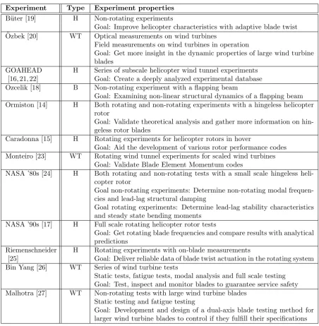
Table 2.2: Reviewed previous experiments
Experiment Type Experiment properties
B¨uter [19] H Non-rotating experiments
Goal: Improve helicopter characteristics with adaptive blade twist ¨
Ozbek [20] WT Optical measurements on wind turbines
Field measurements on wind turbines in operation
Goal: Get more insight in the dynamic properties of large wind turbine blades
GOAHEAD H Series of subscale helicopter wind tunnel experiments [16, 21, 22] Goal: Create a deeply analyzed experimental database Ozcelik [18] B Non-rotating experiment with a flapping beam
Goal: Examining non-linear structural dynamics of a flapping beam Ormiston [14] H Both rotating and non-rotating experiments with a hingeless helicopter
rotor
Goal: Validate theoretical analysis and gather more information on hin-geless rotor blades
Caradonna [15] H Rotating experiments for helicopter rotors in hover
Goal: Aid the development of various rotor performance codes Monteiro [23] WT Rotating wind tunnel experiments for scaled wind turbines
Goal: Validate Blade Element Momentum codes
NASA ’80s [24] H Both rotating and non-rotating tests with a small scale hingeless heli-copter rotor
Goal non-rotating experiments: Determine non-rotating modal frequen-cies and lead-lag structural damping
Goal rotating experiments: Determine lead-lag stability characteristics and steady state bending moments
NASA ’90s [17] H Full scale rotating helicopter rotor tests
Goal: Get rotating blade frequencies and compare results with analytical predictions
Riemenschneider H Rotating experiments with on-blade measurements
[25] Goal: Deliver reliable data of blade twist actuation in the rotating system Bin Yang [26] WT Series of wind turbine tests
Static tests, fatigue tests, modal analysis and full scale testing Goal: Test, inspect and monitor blades to guarantee service safety Malhotra [27] WT Non-rotating tests with large wind turbine blades
Static testing and fatigue testing
Goal: Development and design of a dual-axis blade testing method for larger wind turbine blades to control if they fulfill their specifications
Abbreviations
H Helicopter WT Wind turbine
2.2.1
On-blade monitoring in the rotating system
Four of the reviewed experiments made use of on-blade monitoring in the rotating system, i.e. the two experiments of NASA [17, 24], the GOAHEAD project [16, 21, 22] and Riemenschneider’s research [25]. These experiments will first be described.
NASA ’80s
The experiments described in the technical report of Sharpe were performed for NASA in the 1980s [24]. The goal of this research was to generate more knowledge about the characteristics of hingeless helicopter rotors; these rotors were relatively new in the time of this research. Non-rotating tests were performed to determine the modal frequencies and lead-lag structural damping. For the non-rotating tests, all DOFs were being monitored.
Besides these tests, rotating tests were performed to determine stability characteristics for lagging motion. Only lagging was monitored for the rotating tests. The rotating frequencies could only be calculated, no attempts were made to determine these experimentally, since this was not possible with the available equipment. For both types of tests, lagging was the only excited DOF, this was done by a shaker.
NASA ’90s
In the 1990s, another research regarding helicopters was performed by NASA, which is described in the technical report of Keats Wilkie [17]. The tests performed for this research made use of a four-bladed fully articulated rotor hub. The experiment described in the report was performed to evaluate a modified finite element method, which includes rotational effects for hub designs. The tests were conducted in the Langley Helicopter Hover Facility, a high-bay facility for hover testing, see figure 2.5.
Figure 2.5: Helicopter Hover Facility for NASA’s experiments
This experiment made use of on-blade monitoring, but instrumentation of the blade was limited. For this reason, only elastic blade frequencies up to and including the first elastic feathering mode were measured. Besides, no attempt to measure the blade mode shapes was made.
GOAHEAD
For the GOAHEAD (Generation Of an Advanced Helicopter Experimental Aerodynamic Database) project, multiple wind tunnel experiments were performed with a scaled model of a complete helicopter. Main goal of this project was to create an experimental database for the validation of 3D computational fluid dynamics and comprehensive aeromechanics methods for complete helicopter configurations [16,22]. For these wind tunnel experiments, more than 800 sensors were used for all the measurements. Most of these sensors were located on the helicopter fuselage, however, strain gages and pressure transducers were also used on the rotor and blades. The GOAHEAD project succeeded in creating a comprehensive database with data and documentation for complete helicopters. Besides, the CFD solvers that were applied were capable to perform simulations with good accuracy.
Riemenschneider
The experiment of Riemenschneider [25] also made use of on-blade monitoring in the rotating system. Multiple strain gages were used to retrieve data of the blade. Instrumentation of this experiment was described to be a complex procedure, due to the many wires running through the blade. The setup of this experiment consisted of a single rotating blade, of which the pitch was controlled. The research focused on the design and evaluation of a reliable measuring concept that would be used to generate data about the blade actuation. The most complex part of this was to determine the blade tip twist angle. It was concluded that it was impossible to determine this angle with acceleration sensors, so optical measurements were performed to determine it.
2.2.2
Other type of experiments
The experiments just described all made use of on-blade monitoring in the rotating system. Besides these, other experiments that did not make use of on-blade monitoring in the rotating system were reviewed. Some of these experiments will now be described.
Ormiston
As for NASA’s tests in the 1980s, the experiment described by Ormiston aimed at gathering more knowledge about hingeless helicopter rotors [14]. Both rotating and non-rotating tests were performed. The goal of these non-rotating tests was to measure the bending moments of the blades which are caused by flap and lag. The rotating tests examined both steady state and transient operation. For the transient tests, a shaker was used to excite the fixed hub in a direction parallel to the plane of rotation. This excitation was done at the lagging natural frequency.
The research has provided more knowledge about the behavior of hingeless helicopter rotors. In the time of this research (1972), hingeless helicopter rotors were not widely used, so for a rational approach to the design of these systems, more knowledge about the behavior of these rotors was important.
Adaptive blade twist
Wind turbine blade testing
As the size of wind turbines becomes bigger, the necessity of testing, inspecting and monitoring the blades increases to be able to guarantee their service safety. The paper of Bin Yang [26] describes different technologies to test these wind turbine blades, of which the fatigue tests are interesting for this research. These fatigue tests were performed for both flap and lag, but these tests were performed separately from each other. The paper of Malhotra [27] also deals with the testing of large wind turbine blades. This research introduces a new type of testing, in which flap and lag are excited simultaneously for the fatigue tests. This method of excitation might be interesting to consider when both flap and lag are to be excited for the demonstrator.
Monitoring of wind turbines
For ¨Ozbek’s PhD thesis [20], optical measurements on wind turbines in operation were performed. This was done with the goal to generate more knowledge about the dynamic properties of large wind turbines. The setup of these measurements is shown in figure 2.6. The wind turbine was monitored from three different positions at large distance from the turbine. Multiple markers were installed on the blades to be able to monitor the system more accurately. The accuracy of these measurements will depend on several factors, both controllable (e.g. camera resolution) and uncontrollable (e.g. the weather). Due to the large distance between the cameras and the wind turbine, the accuracy of the data can be questioned.
Figure 2.6: The measurement setup of ¨Ozbek’s research [20]
2.3
Classification of experiments
The classification on the basis of the main purpose is shown in table 2.3. For the demonstrator of this thesis, the goal is to test monitoring strategies for maintenance purposes, so it would be classified best in the last column of the table.
Table 2.3: Main goals of the reviewed experiments
Performance/control Validation of soft-ware codes
Generate insight in the behavior
Service/maintenance testing
B¨uter GOAHEAD Ozcelik Bin Yang
Caradonna Ormiston Ozbek¨ Malhotra
Riemenschneider Monteiro NASA 80s
NASA 90s
The classification of the setups of the different experiments is done on the basis of the DOFs which were being excited and monitored. This classification is shown in table 2.4. As can be seen, the table is divided into four quarters. This division is made on the basis of the number of DOFs that are monitored and excited. The experiments in the first quarter excite and monitor maximum one DOF, while for the experiments of the fourth section the number of excited and monitored DOFs are both at least two.
Table 2.4: Classification of the reviewed experiments
MONITORED DOFS
None Fe Fl L Fe+Fl Fe+L Fl+L Fe+Fl+L
EX
CITED
DOFS
None [15](R)[23](R) [20](R) [16](R)
Fe [25](R) [17](R)
Fl [26](NR) [18](NR)
L [26](NR) [24](R) [14](R) [24](NR)
Fe+Fl [19](NR)
Fe+L
Fl+L [27](NR) [14](NR)
Fe+Fl+L
References Abbreviations
[14] Ormiston Fe Feathering
[15] Caradonna Fl Flap
[16] GOAHEAD L Lag
[17] NASA ’90s R Rotating
[18] Ozcelik NR Non-rotating
[19] B¨uter [20] Ozbek¨ [23] Monteiro [24] NASA ’80s [25] Riemenschneider [26] Bin Yang [27] Malhotra
2.4
Conclusion of experiments
sensors. By doing this, the accuracy of the measurements does not depend on uncontrollable factors such as the weather anymore. For the tests in the last column, the fatigue tests of wind turbine blades performed in the experiments of Bin Yang and Malhotra, developing fatigue cracks could be detected in an earlier stage with on-blade monitoring.
As can be concluded from the classification of the reviewed experiments, not much experimental research has been done where multiple DOFs are excited and monitored, i.e. the shaded quarter in table 2.4. When on-blade monitoring will be implied in RBS it is favorable that all DOFs are being monitored, to be able to detect different damage scenarios.
3. Design process
The first chapters of this report described the problem and provided required knowledge on the subject of this thesis. This chapter will go into detail on the first phase of the design process. The demonstrator will first be described through the FBS framework. After this, a set of design requirements for the demonstrator is listed. On the basis of the FBS-framework and the design requirements, the design procedure that is followed is described. Furthermore, the first design decisions that were taken are described and motivated at the end of this chapter.
3.1
Function
With the FBS of the helicopter rotor described in the previous chapter, the characteristics of the demon-strator that are desired become more clear. This FBS framework was done to get a better understanding of the RBS. The FBS framework will also be used as a guideline for the design of the demonstrator.
The function of the demonstrator is to represent the behavior of a helicopter RBS. As stated in section 1.2, the complexity will be reduced for the demonstrator, so the desired behavior should be clear. The list below sums up the different types of behavior of a helicopter RBS.
• Rotation of blades
• DOFs (Flap, lag, feathering)
• Vary pitch angle to control the position of the helicopter
• Display modes according to table 2.1
3.2
Behavior
The decision of what kind of behavior is desired for the demonstrator is an important one, because the design fully depends on it. For rotating scaled rotor models, the blade tip speed is considered to be an important parameter to keep constant [28]. If for example a 50% scaled rotor model will be used, the rotational velocity will have to be doubled to keep the blade tip speed constant. In other words, the rotational velocity will change in inversely proportion with the scaling. Taking in mind the available space for the demonstrator, scaling will certainly be necessary for the demonstrator. Due to the safety precautions that have to be taken with the resulting high rotational velocity of the system, the rotating aspect is the first type of behavior that was excluded.
The desired behavior of the demonstrator is listed as follows:
• Display flap, lag and rigid feathering
• Display the first three modes according to table 2.1
This means that the demonstrator should be able to display all DOFs. As explained in section 1.1.1, cyclic pitch is the change of pitch over each rotation. This can be simulated in a non-rotating system by actuating the pitch angle with a sinusoidal function. The frequency of this function will represent the rotor frequency Ω. The third type of desired behavior listed regards table 2.1. The frequencies of the first three modes, i.e. rigid lag (flr), rigid flap (ffr) and the first elastic flapping mode (ffel,1) should
be in the same range with respect to the actuation frequency Ω as in the table. This means that one frequency can be chosen out of Ω,ffr,flr andffel,1, while the other three are then decided.
3.3
Structure
This section describes the structure of the demonstrator to complete the FBS-framework. It will first describe the rotor type that should be represented. Next, the actuation of the system will be discussed. Furthermore, the structure of the demonstrator will be described as a series of subsystems.
Rotor type
With the desire to let the demonstrator display the first couple of modes according to table 2.1, the rotor type that should be represented by the demonstrator is already clear. To be able to display both rigid flap and lag, the demonstrator should contain hinges for these DOFs, which means that it represents a fully articulated rotor.
Actuation
For the actuation, it should be decided which modes will be actuated. In a helicopter, rotation and pitch are directly actuated by the engine and the pilot, while flap, lag and elastic feathering are a result of the rotation of the blades, aerodynamic loads, Coriolis forces and unequal lift distribution over the rotor disk.
For the demonstrator, the actuation of pitch should be at constant frequency Ω, because this is also the case in helicopters. For the other modes, actuation at constant frequency will not give a realistic image of the situation in helicopters. If these other modes will be actuated, this should be done at a broadband frequency signal. A possible way to do this, is by actuating it with a noise signal from a shaker.
Subsystems
The total system of the demonstrator can be divided into several subsystems. As mentioned, the demon-strator should contain hinges for all these DOFs. Five different main subsystems can be pointed out, i.e. the blade, the three hinges and the actuation.
The sequence in which the hinges are ordered is important for the design, because the frequencies of the different modes depend on them. If for example the hinges for lag and pitch are located between the flap hinge and the blade, then these hinges experience the flapping movement that is released by the flap hinge. This means that the lag and pitch hinges should be considered in the design process of the flap hinge to realize the desired frequencies.
1 2 3 4 5 6 7 8
Pitch hinge Lag hinge Flap hinge Blade
Figure 3.1: Global structure of the demonstrator
taken into account. Since the lag hinge determines one frequency and the pitch link determines none, it is decided to locate the lag hinge directly after the flap hinge, so that the design of the pitch link does not display lag and therefore does not affect the lagging frequencies. Besides, the fact that the pitch hinge does not display flap and lag makes it easier to actuate it. The global structure of the demonstrator without actuation is shown in figure 3.1. As can be seen, this figure shows eight subsystems, i.e. the four remaining main subsystems (blade and hinges) and the connections between them:
1. Connection between rigid world and the demonstrator
2. Pitch hinge
3. Pitch-lag connection
4. Lag hinge
5. Lag-flap connection
6. Flap hinge
7. Flap-blade connection
8. Blade
3.4
Design requirements
On the basis of the FBS analysis performed in the previous sections, a set of design requirements can be listed for the demonstrator. This section gives an overview of the design requirements. The requirements are classified into three different types; behavior, structure and monitoring requirements.
Behavior
• DOFs: The demonstrator should display flap, lag and rigid feathering.
• Frequencies: The frequencies Ω,flr,ffr andffel,1 should be related to each other as in table 2.1.
Structure
• Rotor type: The demonstrator should represent a fully articulated rotor; it must contain hinges for flap and lag.
• Balancing: The demonstrator should be self-balancing; there must be a neutral position to which it returns when displaying flap or lag.
• Blade profile: To be able to test different blade profiles, the demonstrator will have to be designed such that the blade can be easily replaced.
Monitoring
• Operation frequency: To keep the option of implementing a shaker open, the operation frequency (Ω) should be at least 10Hz. Many shakers have a frequency range that starts at 10Hz, so when a lower operation frequency is chosen, the usefulness of the low-frequent data can be questioned when a shaker is used.
• DOFs: Flap and lag should be monitored to be able to determine the different mode frequencies for which the demonstrator is designed.
3.5
Design procedure
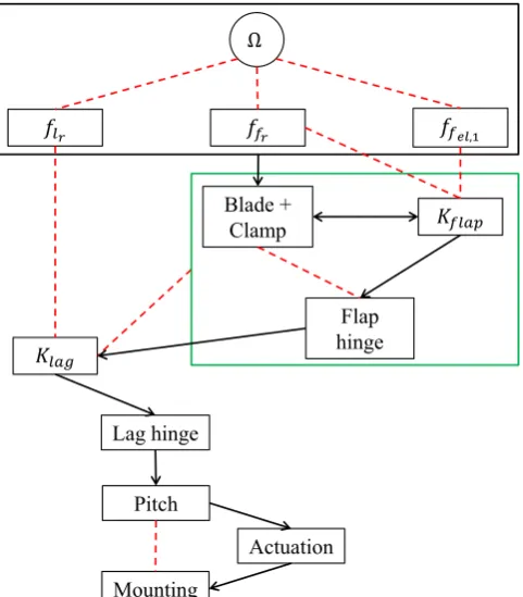
Section 3.3 divided the total system of the demonstrator into five main subsystems. Several relations that are important to keep in mind during the design process exist between the different subsystems. The design procedure that was followed is schematically shown in figure 3.2. In this figure, black arrows define the path of the design process. The red dashed lines represent direct relations between the two elements it connects. Kf lap andKlag represent added stiffnesses in the hinges that are required to realize the desired frequencies for the corresponding modes.
The first thing that was done during the design process, was to choose the operation frequency Ω. With this frequency chosen, the resulting target frequencies ffr, flr and ffel,1 are calculated to realize the
same ratios as in table 2.1. After choosing Ω, the black box at the top of figure 3.2 is completely decided. With the desired frequencies known, the demonstrator was designed from section 8 to 1 according to the numbering of figure 3.1.
𝐾𝑙𝑎𝑔
Lag hinge
Pitch
Mounting
Actuation Blade +
Clamp 𝐾𝑓𝑙𝑎𝑝
Flap hinge
Ω
[image:38.595.183.424.427.702.2]𝑓𝑙𝑟 𝑓𝑓𝑟 𝑓𝑓𝑒𝑙,1
3.6
First design decisions
This section gives an overview of the first decisions that were taken during the design process.
Operation frequency
As mentioned in the previous section, the operation frequency was the first thing that was chosen. The design requirements state that an operation frequency of at least 10Hz is required to gather useful data. Since an increase in the desired mode frequency will lead to an increase in the system’s stiffness to be able to realize this frequency, it is decided to work with the minimal operation frequency (Ω = 10Hz), to prevent the system from becoming too stiff. With this operation frequency, the desired frequencies for the three other modes are calculated:
• flr = 0.3Ω = 3Hz
• ffr= 1.04Ω = 10.4Hz
• ffel,1= 2.68Ω = 26.8Hz
Actuation
Besides actuating pitch at constant frequency Ω, it is decided to actuate flap as well. It is considered to be too complex to actuate both flap and lag besides pitch. Because the demonstrator has two desired frequencies for flapping modes while only having one for lag, excitation of flap is more interesting than it is for lag. Lagging can be activated by introducing an unbalance in lag, it will however not constantly be actuated.
Material
The main material used in the demonstrator is aluminium. The advantage of aluminium is that it has sufficient strength, without becoming too heavy.
Blade orientation
The demonstrator is required to be self-balancing. As mentioned in the FBS-framework, the demonstrator is not desired to display rotation. To realize the self-balancing requirement, it is decided to let the blade hang, so that it is self-balancing by the gravitational loading. By doing this, no pretension is needed to balance the system. Besides, due to centrifugal loads, the effect of the gravitational loading is minimal on a rotating helicopter blade.
Global blade dimensions
3.7
Summary
This chapter described the first phase of the design process. This last concluding section will give an overview of where the design process stands after this chapter.
The desired frequencies are set as follows:
Ω = 10Hz Controlled rotor frequency
flr = 0.3Ω = 3Hz Restrained rotor/blade frequency ffr = 1.04Ω = 10.4Hz Restrained rotor/blade frequency ffel,1 = 2.68Ω = 26.8Hz Restrained rotor/blade frequency
The pitch will be actuated at Ω, while the design of the flap and lag hinges will have to result in the other three frequencies.
The demonstrator will be actuated by two different excitation sources. Pitch will be actuated at a con-stant frequency Ω, while flap is to be actuated at a broadband frequency signal to mimic a more realistic situation for the helicopter blade. By having two independent excitation sources for the demonstrator, it can be placed in the ‘empty’ shaded quarter of table 2.4, with two DOFs being actuated independently and all being monitored.
2 3 4 5 6 7 8
F
P L B
AP 10 AF
1
9
Figure 3.3: Schematic structure of the demonstrator
Figure 3.1 in section 3.3 showed the global structure of the demonstrator without actuation. Now that it is decided which DOFs are being actuated, a more detailed structure can be sketched. This updated structure is shown in figure 3.3. In this figure, the black subsystems form the actual demonstrator. The red parts represents the actuation sources, they are connected to the pitch and flap hinges. The blue part forms the frame in which the demonstrator will be mounted. As can be seen, ten subsections are identified:
1. Connecting frame
2. Pitch hinge
3. Pitch-lag connection
4. Lag hinge
5. Lag-flap connection
6. Flap hinge
7. Flap-blade connection
8. Blade
9. Actuation of flap
4. Design of the demonstrator
The previous chapter described the first phase of the design process. This chapter will go into detail on the actual design of the demonstrator, i.e. the black subsystems of figure 3.3. The design process went from subsystem 8 to 2; the blade and its clamp were first designed, followed by the flap hinge, lag hinge and the pitch hinge. The modeling CAD software package SolidWorks was used for the design of the demonstrator. This chapter will first present the final design of the demonstrator, after which the design of the individual subsystems is described.
4.1
End result
The final design of the demonstrator is shown in figure 4.1. In this figure, the red dashed line represents the flap axis, the yellow one represents the lag axis and the black one represents the pitch axis.
2: Lag torsion spring
3: Flexure mechanism
1: Flap torsion spring 4: Actuation point
for pitch Pitch axis
[image:41.595.161.435.390.641.2]Lag axis Flap axis
Figure 4.1: The final design of the demonstrator
The numbers in the figure represent the following:
2. Torsion spring that is used to generate a rotational stiffness in the lag hinge, this is needed to realize the desired rigid body frequency for lag. The selection of this torsion spring is described in section 4.4.
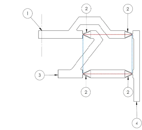
3. Flexure mechanism that is used to be able to actuate flapping at a point that only rotates when pitch is actuated. Because of this flexure, the actuation source for flapping can be mounted in a non-moving environment, while exerting a force on a point that displays flap and lag. The red dot is the point where the flexure will be actuated, this point is located on the pitch axis, so it will only rotate along with pitch. The design of the flexure is described in section 5.1.
4. The point where pitch will be actuated. It is decided to actuate pitch with a translational actuator. The selection of an actuator is described in section 5.2.
4.2
Blade clamp
[image:42.595.207.387.412.547.2]As stated in the design requirements, the demonstrator should be designed such that the blade can be easily replaced. This is required to be able to test different blade profiles with it. To make it possible to replace the blade easily, it is decided to use a blade clamp as a connecting part between the flap hinge and the blade. This part will be replaced with other blade configurations. The section that clamps the blade will change with other blade profiles, while the section that is connected to the flap hinge will have to be the same for all blade configurations.
Figure 4.2 shows the design of the blade clamp. The bottom section is the specific part where the blade will be clamped, this is the part that will change for different blade configurations. The design of this specific section depends on the blade profile that is used. The top section is the generic part that will be mounted in the flap hinge. This end section is 30mm wide, 10mm thick and 16mm high.
Generic
Specific
Figure 4.2: Design of the blade clamp
4.3
Flap hinge
This section describes the design of the flap hinge. At first, the design process of the hinge is explained, followed by the actual design of the hinge.
4.3.1
Design process
The design requirements state that the ratios between the different mode frequencies of the demonstrator should give a representation of a real helicopter RBS; the rigid and the first elastic flapping mode frequencies should be in the same range with respect to the operation frequency Ω as they are in table 2.1. To realize the desired flapping frequencies, an added rotational stiffness is necessary in the flap hinge. The effect of this added rotational stiffness on the elastic body frequency of the blade is determined in appendix A. It appears that adding a rotational stiffness in the hinge leads to a decrease of the bending frequency, while increasing the rigid body frequency.
With the method described in the appendix, it is possible to calculate the elastic body frequency when the blade parameters and the rotational stiffness are known. To get both the rigid and elastic body frequencies in the range of the desired frequencies, the blade parameters can be changed. The iterative process of figure 3.2 is schematically shown in figure 4.3. For the initial blade design, the required rotational stiffness for the rigid flapping frequency is calculated. With the stiffness known, the resulting elastic flapping frequency is calculated using the method of appendix A. If this fulfills the design requirements, the required rotational stiffness is known and the flap hinge can be designed. If the result is not good enough, the parameters of the blade are changed until the requirements are fulfilled.
Initial blade
design 𝑓𝑓𝑟 𝐾𝑓𝑙𝑎𝑝 𝑓𝑓𝑒𝑙,1
Satisfying result?
Change 𝐿 of the blade
Flap hinge
Figure 4.3: Iterative process to realize the desired frequencies
As can be seen in this figure, only the length of the blade was changed when the desired frequencies were not realized. This is done because the width of the blade does not have an effect on the natural frequen-cies, while it is favorable to use a standard thickness for the blade; a thickness of 4mm is used. Following this process, the required rotational stiffness and blade length were found to beCF ≈2.2Nm/deg and L= 551mm.
4.3.2
Hinge design
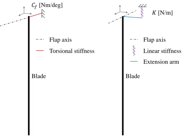
There are different ways to generate a rotational stiffness in the flap hinge. It can be done by placing a torsion spring directly on the flap axis. However, if small angles are assumed, the torsional stiffness can also be generated by placing a linear stiffness at a certain distance from the flap axis. See figure 4.4.
It is decided to generate the rotational stiffness by using an external stiffness at a certain distance from the flap hinge. When the rotational stiffness is generated at the outside of the system, it is easy to replace it when other blade configurations that require a different stiffness are used. Besides, when an external stiffness is used, it will be easier to control the distance between the hinges; a quick investigation of standard torsion springs that could be used shows that relatively large torsion springs are needed to realize the required rotational stiffness in the hinge. This automatically means that the hinge itself, and thus the distance between the flap and lag hinge, will become large as well. The distance between these hinges will quickly become around 15 to 20% of the blade length. This is highly unfavorable; the different axes are all close to the root in a fully articulated helicopter rotor, so to better represent a helicopter RBS, it is favorable to keep the distance between the hinges as small as possible.
Flap axis
Linear stiffness
Blade
Extension arm 𝐾[N/m] 𝐶𝑓[Nm/deg]
Flap axis
Torsional stiffness
Blade
[image:44.595.142.455.75.309.2]Figure 4.4: Two ways to generate a rotational stiffness in the hinge
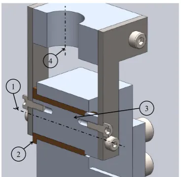
Figure 4.5: Torsion spring end design
standard springs, including torsion springs [29]. It was possible to customize the design of the standard springs to be able to fit them in the design. For the spring that was selected for the flap hinge, the leg length was changed. Besides, the springs’ end design was customized to be able to fit it more easily in the design, see figure 4.5. The legs of the left spring are in the original configuration, while the right one has the customized configuration that is used in the demonstrator.
The torsion spring that was used for the flap hinge is a customized SF-VFR 8503, with a spring rate of 0.488Nm/deg [29]. The arm that was used to connect the torsion spring was arbitrarily chosen to be 50mm. With these parameters, the leg length that was required to realize a rotational stiffness of CF ≈2.2Nm/deg was calculated to be 23.5mm. The derivation of this required leg length is explained in appendix B.
At this stage of the design process of the flap hinge, it is known how the torsion spring is going to be implemented in the hinge. Besides, the hinge should contain a clamping section to connect the blade. These are the two most important characteristics of the hinge, so the rest of the design of the hinge can now be done. Figure 4.6 shows the final design of the flap hinge. The bottom section is the part that clamps the blade, the black dashed line is the flap axis and the arm in the front is the part where the torsion spring is connected.
Flap axis
Blade connection Connection with
torsion spring
Figure 4.6: Design of the flap hinge
Connection with lag hinge
Flap torsion spring Flap axis
50mm 23.5mm
Figure 4.7: Assembly of subsystems 6 to 8
4.4
Lag hinge
Following the procedure of figure 3.2, the design of the lag hinge is next in the process. This section will describe the design of this hinge. The following requirements are made for the design:
• Form a connection with the flap torsion spring
• Form a connection to the flap axis, while releasing the flapping motion of the flap hinge
• Generate a rotational stiffness that results in a rigid lagging frequency offlr ≈3Hz
When looking at the schematic structure of the demonstrator in figure 3.3, the subsystems 6, 7 and 8 are already designed at this stage. Because these parts will all display lag in the demonstrator, they should be taken into account to be able to calculate the required rotational stiffness of the lag hinge. It is desired to have the lag and the flap axes close to each other, to generate a more realistic representation of a helicopter rotor. For this reason, it is decided to make use of an external torsion spring for the lag hinge as well.
leg length was calculated with the method of appendix B, this turned out to be 36.4mm with an arm of 50mm for the lag axis.
The design of the lag hinge is shown in figure 4.8. As can be seen, the hinge has two arms. The bottom one is the arm that connects to the torsion spring of the flap hinge, while the top one connects to the lag torsion spring. To ease the manufacturing process of the lag hinge, it will be made out of two pieces. The arm that is connected to the lag torsion spring will be made as a separate part and will be mounted to the rest of the hinge by bolts.
Connection with flap torsion spring Connection with
lag torsion spring
Lag axis
Figure 4.8: Design of the lag hinge
With the lag hinge designed, the assembly can be updated to a system where subsystems 4 to 8 are present. This updated assembly is shown in figure 4.9. The flap hinge is made transparent in this figure, to clarify how the flap and lag hinges are connected to each other. As can be seen, the flap shaft is connected to the lag hinge. The flapping motion is released by two standard plain bearings between the flap shaft and the hinge. The parts used for this are standard bronze plain bearings (GLI BBF 061010) that are ordered at Brammer [30]. The numbers in the figure indicate the following:
1. Flap axis
2. Flap torsion spring
3. Plain bearings used to release flapping motion between the flap hinge and shaft
4. Lag axis
5. Lag torsion spring
6. Connection with pitch hinge
1
2 3
5
4 6
Connection with lag torsion spring
Pitch axis
Figure 4.10: Design of the pitch hinge
4.5
Pitch hinge
At this stage of the design process, the blade, the flap hinge and the lag hinge are all designed. The torsion spring of the lag hinge has to be connected to the next hinge, i.e. the pitch hinge. This section describes the design process of this last hinge. This is the least complex of the three hinges, because it has no constraints for mode frequencies. The three desired frequenciesflr,ffr andffel,1are all constraint by the flap and lag hinges, while the frequency corresponding to pitch will be actuated at the operation frequency.
The requirements for the pitch hinge are listed as follows:
• Connect to the lag torsion spring
• Form a connection with the lag axis, while releasing the lagging motion of the lag hinge
The design of the pitch hinge is shown in figure 4.10. The arm in the front of this figure will be connected to the lag torsion spring. The threaded holes on both sides are to mount the connection plates to the sides. These plates are made out of 2mm thick steel and will be made by laser cutting. They are used to connect the pitch hinge to the lag shaft.
With the pitch hinge designed, the assembly of subsystems 2 to 8 can be made. This updated assembly is shown in figure 4.11. The lagging motion is released by a plain bearing between the lag shaft and the lag hinge. This is shown in figure 4.12. This figure shows the section view of the rectangular area in figure 4.11. The bearing that is used for this, is a standard bronze plain bearing (GLI BBF 101320) that is ordered at Brammer [30]. The numbers in the figure indicate the following:
1. Lag axis
2. Plain bearing that is used to release lagging motion between the lag hinge and shaft
3. Lag shaft
4. Pitch axis
4.6
Summary
Figure 4.11: Assembly of subsystems 2 to 8
2
3 1
4
Figure 4.12: Section view of the connection to the lag hinge
![Table 2.1: First blade natural frequencies in terms of rotor frequency Ω [10]](https://thumb-us.123doks.com/thumbv2/123dok_us/9900194.491363/26.595.198.394.131.240/table-blade-natural-frequencies-terms-rotor-frequency.webp)