University of Southampton Research Repository
ePrints Soton
Copyright © and Moral Rights for this thesis are retained by the author and/or other copyright owners. A copy can be downloaded for personal non-commercial
research or study, without prior permission or charge. This thesis cannot be
reproduced or quoted extensively from without first obtaining permission in writing from the copyright holder/s. The content must not be changed in any way or sold commercially in any format or medium without the formal permission of the
copyright holders.
When referring to this work, full bibliographic details including the author, title, awarding institution and date of the thesis must be given e.g.
UNIVERSITY OF SOUTHAMPTON
ADVANCED BRAGG GRATING BASED
INTEGRATED OPTICAL DEVICES FOR
WAVELENGTH DIVISION MULTIPLEXING SYSTEMS
By
Christos Riziotis
A Thesis submitted for the degree of
Doctor of Philosophy
FACULTY OF ENGINEERING AND APPLIED SCIENCE
DEPARTMENT OF ELECTRONICS AND
COMPUTER SCIENCE
OPTOELECTRONICS RESEARCH CENTRE
UNIVERSITY OF SOUTHAMPTON
ABSTRACT
FACULTY OF ENGINEERING AND APPLIED SCIENCE
DEPARTMENT OF ELECTRONICS
AND COMPUTER SCIENCE
OPTOELECTRONICS RESEARCH CENTRE
Doctor of Philosophy
ADVANCED BRAGG GRATING BASED
INTEGRATED OPTICAL DEVICES FOR
WAVELENGTH DIVISION MULTIPLEXING SYSTEMS
by Christos Riziotis
This thesis presents experimental and theoretical work towards the development of advanced integrated planar optical devices for application in Wavelength Division Multiplexing (WDM) in optical communication systems. The presented work lies within a broad range of research areas, namely: design and simulation of novel Bragg grating based WDM passive devices, their performance characterization in simulated optical communication systems, fabrication and characterization of photosensitive thin films and finally device fabrication using ultraviolet induced refractive index changes. A complete model for the analysis of Bragg grating assisted devices in waveguide structures has been developed. Bragg grating based optical Add/Drop Multiplexers (OADM) have been simulated and studied by using this modelling tool. A fully optimised design for an OADM based on a null coupler and a tilted Bragg grating has been proposed. This device can exhibit optimised Add and Drop actions with suppressed backreflections and crosstalk to a level lower than –40 dB. A novel interferometric OADM configuration based on a full cycle full (100%) coupler is also proposed. This design exhibits fully optimised and symmetrical Add/Drop actions in contrast to the compromised performance of traditional interferometric configurations.
A software simulation tool has also been developed and employed for the theoretical characterization of optical filters, linking this way the proposed devices to real communication system issues related to high bit rate WDM networks. The effect of group delay ripple in WDM filters is studied for different modulation formats and a simplified figure of merit is proposed for the characterization of the effect.
For the fabrication of photosensitive thin film structures, a prototype in-house Flame Hydrolysis Deposition facility was built and it was initially characterized. Further experimental work involved detailed analysis and characterization of highly photosensitive Lead Germanate glasses grown by Pulsed Laser Deposition.
A developed direct UV-writing facility is presented and major issues around the functionality of the technique are discussed, by demonstrating solutions for the control of the optical system.
Table of Contents
Acknowledgements vii
List of Abbreviations viii
Introduction 1
Chapter 1: Passive Optical Devices
for Wavelength Division Multiplexing Systems 6
1.1 Introduction 6
1.2 General properties of optical filters 8
1.3 Arrayed waveguide gratings 10
1.4 Thin film filters 12
1.5 Bragg grating based filters 14
1.6 Comparison of specially designed Bragg grating filters with TFF 15
1.7 Bragg grating based OADMs 19
1.8 References 24
Chapter 2: Analysis and Modelling of Bragg Grating Assisted
Waveguide Devices 29
2.1 Introduction 29
2.2 Local normal mode analysis and step transition model 31 2.2.1 Dispersion equation for the five layer waveguide structure 32 2.2.2 Step-wise approximation of waveguide structures 33 2.3 General analysis of a non-uniform Bragg grating 36 2.4 Analysis of the composite grating-coupler structure 41
2.4.2 Calculation of the response of the composite structure 42
2.5 Summary 43
2.6 References 43
Appendix 2.A: Pseudo-algorithm for the step transition model 46
Chapter 3: Null Coupler -Tilted Bragg Grating Based OADM 47
3.1 Introduction 47
3.2 Principle of operation 47
3.3 Null coupler design and optimisation 49
3.3.1 Waveguide asymmetry optimisation 50
3.3.2 Taper shape optimisation 51
3.4 Grating section 55
3.4.1 Calculation of tilted Bragg grating’s coupling coefficients 56
3.4.2 Tilted grating optimisation 57
3.5 Full spectral response of the OADM 63
3.6 Conclusions 71
3.7 References 72
Appendix 3.A: Analytical expressions for the optimum tilt angle 75
Chapter 4: Full Coupler Based Interferometric OADM 77
4.1 Introduction 77
4.2 Half-cycle coupler (HCC) based OADM 77
4.3 Full-cycle coupler (FCC) based OADM 87
4.3.1 Design procedure 88
4.4 Spectral response of the full-cycle coupler (FCC) based OADM 94
4.5 Conclusions 101
Chapter 5: Characterization of Optical Filters in
High Speed WDM Transmission Systems 103
5.1 Introduction 103
5.2 Simulation of an optical communication system 104 5.3 Fundamental operations in optical network’s nodes 105 5.4 Characterization of half-cycle coupler (HCC) based OADM 106
5.4.1 EOP calculations 110
5.5 Characterization of full-cycle coupler (FCC) based OADM 114
5.5.1 EOP calculations 116
5.5.2 Performance comparison of HCC and FCC OADMs 117 5.6 Effect of group delay ripple on WDM filters performance 121
5.6.1 Time delay ripple definition 121
5.6.2 EOP calculations 122
5.6.3 Time delay ripple figure of merit 126
5.7 References 129
Chapter 6: Fabrication and Characterization
of Photosensitive Thin Film Layers 131
6.1 Introduction 131
6.2 Silica-on-Silicon technology 132
6.3 Devices fabrication technology based on photosensitive films 133 6.4 Photosensitive films fabrication techniques 134 6.5 Flame Hydrolysis Deposition (FHD) technique 135
6.5.1 FHD operational principles 136
6.5.2 FHD prototype facility 142
6.6 Film fabrication considerations related to UV written devices properties 146 6.7 Characterization of photosensitive Lead Germanate optical waveguides 149
6.7.1 Growth of Lead Germanate glasses 149
6.7.2 Properties and loss characterization of the films 152 6.7.3 Photosensitivity of Lead Germanate films 158
Chapter 7: Direct UV-Writing System and Applications 166
7.1 Introduction 166
7.2 Direct UV writing system 168
7.2.1 Writing spot focusing procedure 170
7.3 Photosensitivity of Germanium doped Silica glasses 173 7.4 Photosensitization of Germanium doped Silica thin films 176
7.5 Photosensitivity locking technique 179
7.6 Conclusions 183
7.7 References 184
Chapter 8: Conclusions 187
8.1 Conclusions 187
8.2 Proposed future work 190
Acknowledgments
Firstly, I would like to thank both my supervisors Dr. Peter Smith and Prof. Michalis Zervas for their continuous support, guidance, encouragement and friendship.
Peter was a continuous source of new ideas and he passed to me some of his great ability and talent to think and act effectively as an experimentalist. Michalis entered me into the fascinating world of devices and optical communications. He inspired me and formed in a great degree my attitude towards research. I am also grateful to him for suggesting and helping me to come to Southampton and join this extremely stimulating and international environment of work.
I am grateful also to my ex-supervisor Dr. Richard Laming for suggesting and offering me the research project.
I would like also to thank all the people I worked with during my PhD research. I am grateful to Prof. Rob Eason, Dr. Sakellaris Mailis, Dr. Eleanor Tarbox, Dr. Ricardo Feced, Dr. Richard Williams, Alexander Fu and Carlos Alegria for their help and the skills they passed to me.
I am grateful to my wife Maria for all her help, support, and encouragement during all these years in Southampton …and for the years before.
List of Abbreviations
AFM Atomic Force Microscopy
AWG Arrayed Waveguide Grating
BG Bragg Grating
CW Continuous Wave
DWDM Dense Wavelength Division Multiplexing EDFA Erbium Doped Fibre Amplifier
EOP Eye-Opening Penalty
FCC Full-Cycle Coupler
FFT Fast Fourier Transform
FHD Flame Hydrolysis Deposition
FRED Frequency Doubled (Ar – Ion Laser) GODC Germanium Oxygen Deficient Centres
HCC Half Cycle Coupler
IFFT Inverse Fast Fourier Transform
IM-DD Intensity Modulation – Direct Detection LPCVD Low Pressure Chemical Vapour Deposition
LPF Low Pass Filter
MZI Mach-Zehnder Interferometer
MZM Mach-Zehnder Modulator
NRZ Non Return-to-Zero Modulation format OADM Optical Add/Drop Multiplexer
OC Optical Circulator
OVD Outside Vapour Deposition
PLC Planar Lightwave Circuit
PLD Pulsed Laser Deposition
PRBS Pseudo Random Bit Sequence
RIE Reactive Ion Etching
RZ Return-to-Zero Modulation Format
TFF Thin Film Filter
UV Ultra-Violet
VAD Vapour Axial Deposition
WDM Wavelength Division Multiplexing
INTRODUCTION
Optical Communications is an extremely fast growing technology driven mainly by the increasing need for global expansion of the Internet and multimedia communications. Only the huge bandwidth of the optical fibre seems to be able to accommodate the increasing amount of network traffic today and much more in the future. However, the bandwidth of the 3rd low loss optical window (at around 1550 nm) of single mode optical fibre is currently restricted by the availability and performance of optical amplifiers. For low bandwidth requirements initially only the red C-Band (1540-1563 nm) was used, where the Erbium Doped Fibre Amplifier (EDFA) exhibits a quite flat response. As the need for capacity is increased, the entire C-Band (1530-1570 nm) and even the L-Band (1570-1610) are being used. Additional capacity is also available from the S-band (1480-1520 nm) by using Semiconductor optical amplifiers (SOA), Thulium doped fibre amplifiers (TDFA) or lumped Raman amplifiers.
This thesis describes performed work within a broad range of activities towards the understanding, design and development of passive components for use in WDM transmission systems. Chapter 1 discusses the developing technology of passive components and reviews the main proposed architectures and technologies. The performance and the general characteristics of Thin Film Filters, Arrayed Waveguide Gratings and Bragg grating based devices are discussed. The effect of the spectral characteristics of those filters is studied in conjunction with communication systems issues such as cascading and filter-Laser source misalignments. Various configurations of Bragg grating based Multiplexers and Add/Drop filters are presented and their performance, limitations and related fabrication issues are discussed. The following Chapters of the thesis are dedicated to the underlying fabrication technology of such Bragg grating based passive devices and also to the design, modeling and system characterization of novel high performance Bragg grating based filters.
The choice of the material platform for the development of those devices in the long-term target of this project is Silica-on-Silicon. The aim of the project was to transfer device and fabrication technology of fibre-Bragg gratings into an integrated optics implementation, which forms a more compact, and environmentally stable solution. This implementation adds more degrees of freedom to the device design enabling thus the development and fabrication of much more sophisticated devices with greater density of operation over volume compared with fibre based components. Environmental stability, compactness and device’s functional density are a major concern in future WDM communication systems, since the number of the employed WDM channels is continuously increased.
The first part of the thesis (Chapters 2 to 5) is devoted to the theoretical analysis and characterization of Bragg grating based devices, while the second part (Chapters 6 and 7) describe the experimental part of the work.
Specifically, Chapter 2 presents the analysis and modeling of coupled waveguide structures using the normal modes coupled mode theory. The Chapter describes also the development of the theory for the analysis of non-uniform Bragg gratings employed within multimode waveguide structures. The combination of the two analyses can model successfully any Bragg grating based coupled waveguide device, and is used within the following Chapters for the modelling of the full spectral response of Bragg grating based filters.
Chapter 3 presents a detailed study of a non-interferometric OADM configuration, which is based on mode conversion by using an asymmetric grating perturbation. The Chapter discusses the general properties of a device of this kind and proposes a fully optimized design, which predicts theoretically excellent spectral characteristics. The proposed architecture is more robust than interferometric configurations and its demonstrated performance is compatible with the stringent DWDM components requirements.
Chapter 5 concludes the theoretical work on Optical Add Drop Multiplexers, with simulations of their performance characteristics when deployed in high bit rate WDM transmission systems. A complete simulation tool has been developed during this work, which allows the simulation of passive devices in an optical communication system. The developed software can incorporate many system parameters, like different modulation formats and line codes, pulse shaping through filters and Mach-Zehnder modulators, filter- misalignments and cascades. The analysis of a communication system and the description of the simulation tool are described initially and applied in the characterization process of some cases of WDM filters.
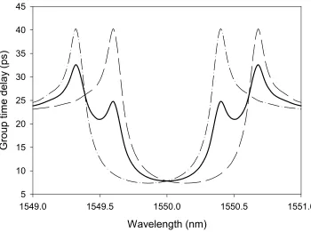
Based on this tool the intra-band characteristics of the Half and Full cycle 100% coupler based OADM –discussed in Chapter 4- are examined. Conclusions are made about the resulting system penalty due to the spectrally degraded filter response. These filters are compared with the counterpart non-interferometric configuration where the Add and Drop characteristics can be fully optimized. The second part of the chapter is devoted to the study of the dispersion characteristics of OADMs. The shape of in-band group delay and consequently in-band dispersion are studied and conclusions are drawn regarding the performance of traditional Bragg gratings and specially designed dispersion-less gratings. Another important issue related to these novel-grating devices, resulting from design compromises or fabrication imperfections, is the presence of group delay ripples in the in-band reflection spectrum. We thoroughly study the implications of these ripples for different input signal modulation formats and we also firstly propose that the average time delay and not the average dispersion is the appropriate figure of merit, describing more accurately the signal distortion effects.
The second part of Chapter 6 is devoted to the characterization of the properties of photosensitive Lead-Germanate glass optical waveguides grown by the Pulsed Laser Deposition (PLD) technique. This part presents results of a collaborative research project between the ORC and the FORTH Centre (Greece) where these optical glass waveguides were fabricated for the first time using the PLD technique. These waveguides characterized in the ORC and their properties –propagation loss, and photosensitivity- were related to the PLD fabrication parameters.
In Chapter 7 the newly developed ORC prototype facility for direct UV writing is presented. Initially, the main mechanical and optical parts of the system are described. Major issues around the control of the UV writing optics are considered and proposed and implemented solutions are presented. A number of the UV writing experiments performed are discussed and the results confirm and justify the fully operational status of the facility.
In general, the intrinsic photosensitivity of Ge-doped silicate glasses is not sufficient for the definition of all UV written waveguides and gratings. Hydrogen or Deuterium indiffusion into the glass matrix is a standard procedure of critical importance for increasing the photosensitivity. A major drawback of this method is the rapid outdiffusion of the gas from the thin film layer, which consequently leads to fabrication problems due to continuously degraded photosensitivity during the direct UV writing. A novel method based on a rapid heat treatment of the gas-loaded films, is proposed in this thesis in order to overcome the problem. Experiments and initial results are presented suggesting that this method ‘locks’ the enhanced photosensitivity for effectively an infinite period of time. The application of this method should enable in the future the implementation of all directly UV written devices by providing a stable photosensitive layer for further development.
CHAPTER 1
Passive Optical Devices for Wavelength Division
Multiplexing Systems
1.1 Introduction
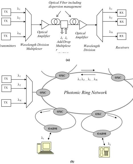
The continuous and global spread of multimedia communications and the Internet can only be accommodated by the huge bandwidth that optical fibre networks can offer. However there is a great demand for expanding the intrinsic capacity and improving the flexibility of optical networks, and the enabling key technology is proven to be Wavelength Division Multiplexing (WDM). This way, the capacity of the already installed optical fibre cable network can be multiplied by the number of employed WDM channels within the system.
Wavelength Division Multiplexer
TX λ1
λ2
λN
Transmitters Wavelength
Division
λ1
λ2
λN
Receivers Optical Fiber including
dispersion management
Optical Amplifier
(a)
λi λi
Add/Drop Multiplexe r
(OADM)
Optical Amplifier
TX
TX RX
RX RX
TX λ1
λ2
λN
TX
TX
OXC
OADM OXC
OADM OXC
OXC OXC
Photonic Ring Network
λ1 λ2 … λi … λNλi
λj
[image:17.595.98.565.90.662.2](b)
In a photonic ring network (Fig. 1.1(b)) the stream of WDM channels enter the ring and they are directed into the subscribers serving nodes by the use of Optical Cross Connects (OXC). Within the nodes, specific channels are Dropped or Added by using Optical Add/Drop Multiplexers (OADM) in order to serve the subscribers.
For the successful implementation of future WDM networks and systems the performance of all these aforementioned passive and active components is of paramount importance. The available bandwidth for today’s optical networks lies between the 1530 - 1570 nm (EDFA C-Band) and is currently being expanded to the L-Band (1570-1610 nm) and S-L-Band (1480-1520 nm) to accommodate the increasing network traffic. For the efficient use of the total optically amplified window the optical device specifications are getting ever more stringent. Indeed, the channel spacing in WDM systems has evolved from 200 or 100 GHz few years ago to 50 GHz and 25 GHz. Furthermore, planned bit-rate migration towards 40 Gbit/s and higher, sets extremely tight requirements especially on WDM components/subsystems and filters. Filters are incorporated in optical multiplexers and demultiplexers as well as OXC and OADMs, and are the most important passive devices used in WDM networks.
This Chapter gives a review of the state of art of different optical filter technologies. The filters are classified into general categories and in some cases their performance is compared using system simulations. Finally an expanded discussion is presented around the Bragg grating based OADM architectures.
1.2 General properties of optical filters
To date there have been proposed many different architectures for optical filters and they have been implemented in many forms. The most representatives are:
• Mach-Zehnder interferometer based filters (MZI) [1.1]
• Arrayed Waveguide Gratings (AWG) [1.2, 1.3] - also known as Waveguide Grating Routers (WGR)
• Thin Film Filters (TFF) [1.5] • Bragg Grating based Filters [1.6]
Based on their fundamental operational principles, these filters can be classified in different classes, which accordingly define the general performance characteristics and limitations of the filters.
DWDM systems, set stringent specifications on optical filters by means of in-band characteristics (flatness, ripple, steepness of the filter edges, dispersion), out-of-band characteristics (crosstalk, side lobes, dispersion), and insertion loss. These characteristics depend on both the particular implementation of the filter but also on their underlying fundamental operational principle. For example, as we will show later, identical Bragg gratings deployed in various device architectures exhibit different filtering characteristics although their operational principle and function is common in all these implementations.
An Arrayed Waveguide Grating (AWG) is a very successful filtering device, especially for applications, which require high count of WDM channels. It is implemented exclusively in integrated planar form, known alternatively as Planar Lightwave Circuit (PLC), on the Silica-on-Silicon platform or alternatively on semiconductor materials (InP). The configuration of an NxN AWG multiplexer is shown in Figure 1.2.
Figure 1.2 Schematic of an NxN Arrayed Waveguide Grating
AWGs have also been fabricated with improved pass-band flatness but at expense of an increased insertion loss of about –8 dB [1.11]. A typical amplitude response for an AWG can be seen in Figure 1.3.
Figure 1.3 Full amplitude response of an AWG with Gaussian type amplitude response (left) and flattened response for an isolated channel (right) (after [1.12, 1.13])
Theoretically, the response of an AWG filter can be expressed as a finite number of weighted fixed delays [1.9]:
=
∑
−1 − 0) ( )
( N h n e j n
H ω ϖ (1.1)
where h(n) is the discrete impulse response and N the number of WGR arms and ω the normalized frequency. This type of response is known in digital filter theory as Finite Impulse Response (FIR). It has been show that theoretically this type of filter is non-MPF and is dispersionless [1.9]. However in real devices, presence of loss in the arrayed waveguides, random phase changes due to errors in the fabrication process, small differences in the input and output slabs and finally losses in the slab waveguides lead to dispersion in the AWG [1.14] and the device becomes a MPF variant. It has been shown recently that the dispersion characteristics of AWGs cannot be considered negligible and lead to substantial system penalties, especially at high bit rates such as 40 Gbit/s [1.14].
1.4 Thin film filters
Thin Film Filters (TFF) [1.5] have started being increasingly popular for WDM applications mainly because of their compactness, simplicity and environmental stability. Their structure is based on that of the Fabry-Perot (F-P) etalon, which is composed of a cavity and mirrors and acts as a bandpass filter. The centre operational wavelength is determined by the cavity length. A narrow-band thin film interference filter consists of more than two F-P cavities separated by dielectric reflection layers with a very high refractive index contrast (typically ∆n≈1). Each cavity contains a multiple-layer structure with more than 50 layers. Typical spectra of TFF are shown in Figure 1.4 and is obvious that the spectral shape is not inherently compatible with the requirements of DWDM technology.
example, fabrication of a 50 GHz filter requires typically several hundred layers of coating-, increased assembly cost and additional insertion loss.
Figure 1.4 Spectra of multicavity TFF [1.5] & detail of spectrum [1.12] (Thick line:Transmission)
The response of the TFF can be generally expressed as that of the reflection spectrum of a general multiple-layer structure [1.9]:
∑
∑
− − −
−
−
= 1
0 1
0 1 )
( N
n j n N
n j n
e a
e b H
ϖ ϖ
ω (1.2)
where coefficients αn, bn, are derived from the reflection coefficients between the different layers and N is the total number of layers. This type of response is known in digital filters theory as Infinite Impulse Response (IIR) and inherently involves a feedback mechanism, as indeed happens in TFF’s given that reflection is an inherently feedback mechanism. In contrast to the FIR type filters described before there is no feedback mechanism as is obviously the case in the operation of AWG’s.
the number of cavities, in order to improve their characteristics, will not only add ripple in the passband but also increase the dispersion near the filter’s edges.
1.5 Bragg grating based filters
Bragg grating filters (BGF) operate in reflection mode and their operational principle can be expressed generally from Equation 1.2. However there are major differences with TFF. Firstly TFF operate, based on a feedback mechanism, in transmission mode. Secondly the layers in photorefractive Bragg gratings involve very small index modulations which consequently means that a BGF is built from many layers and thus is a longer device than a TFF. Spectral characteristics of BGF are also very different than TFF, exhibiting a very flat amplitude response. A typical spectral response of a fiber Bragg grating is shown in Figure 1.5.
BGF have so far been implemented mostly in fibre geometry (FBG) and have the advantage of very low insertion loss and very good spectral characteristics compared with other waveguides based devices.
Figure 1.5 Spectral response of a fiber Bragg grating (Thick line:Reflection, Thin line: Transmission) (after [1.12])
laser irradiation through a phase mask [1.15]. The period of the written Bragg grating is typically around 0.5 µm in order to couple the forward and the backward propagating modes and to be operated in the third telecom window (1550nm). Phase Bragg gratings
written on photosensitive waveguides are much smoother than the etched gratings -used mainly in semiconductor materials - reducing greatly the associated loss. FBG
are very versatile devices and their characteristics can be easily tailored by adjusting suitable fabrication parameters, such as refractive index modulation, length, apodization profile, period chirp, tilt, and phase shift insertion. Advanced Bragg grating writing techniques [1.16] have allowed the fabrication of sophisticated high performance filters based on gratings with arbitrary apodization profiles and phase shifts. Bragg gratings written in coupled waveguide structures, which offer channel routing functions, have also been demonstrated. This class of devices is very important for fabrication of more functional components such as Add/Drop multiplexers and will be discussed later in this Chapter.
1.6 Comparison of specially designed Bragg grating filters with TFF
The spectral properties of phase Bragg gratings can be tailored to a great extent -in contrast with TFFs. This is primarily due to fact that TFF are transmissive devices and therefore the dispersion performance cannot be disentangled from the transmission profile. In addition due to causality, the more square the transmission profile, the larger the in-band dispersion variation [1.9]. It has been proved that spatially asymmetric Bragg gratings, working in reflective mode, are non-MPF and the dispersion spectrum may be defined independently from the reflection spectrum [1.9]. A recently developed inverse scattering technique has allowed efficient and physical realizable designs for high performance Bragg gratings [1.17]. Additionally, advanced fabrication techniques [1.16] have enabled the experimental demonstration of specially designed dispersionless gratings with near rectangular amplitude response [1.18].
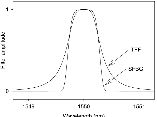
both with FWHM bandwidth of 0.5 nm. By using system simulations –as described in detail in Chapter 5- the effect of cascading is examined for both filters at 10 Gbit/s transmission speed for non-return-to-zero (NRZ) modulation format. The simulated communication system is an Intensity Modulation/Direct Detection system (IM/DD). Figure 1.6 gives the filter’s amplitude response.
Figure 1.6 Amplitude spectral response of TFF and specially designed SFBG
The performance of the filters is quantified by calculating the resulted Eye-Opening penalty (EOP) after passing the signal through the cascade of the filters. Initially we consider that all the cascaded filters are perfectly aligned to each other and also perfectly aligned with the spectrum of the signal source. Figure 1.7 gives the EOP, as a function of the number of cascades of the filters. Is obvious that due to elimination effect of in-band dispersion in the Bragg grating filter and also the better square characteristics of the amplitude response, the distortion effects to the initial signal are negligible even after 200 cascades.
Wavelength (nm)
1549 1550 1551
Filter amplitude
0 1
Figure 1.7 Effect of perfectly aligned cascaded filtering on EOP
Figure 1.8 Effect of uniformly misaligned cascading filtering on EOP
A major issue in real WDM systems is the effect of misalignments of the filters with the laser source. Misalignments can arise from fabrication imperfections, laser/transmitters instabilities, temperature drifts, and due to other environmental
Cascade number
0 50 100 150 200
E
ye-O
pening P
enalt
y (dB
)
0.0 0.5 1.0 1.5 2.0 2.5 3.0 3.5 4.0 4.5 5.0
FBG TFF
Cascade number
0 50 100 150 200
E
ye
-Op
en
in
g P
ena
lty
(d
B
)
0.0 0.2 0.4 0.6 0.8 1.0
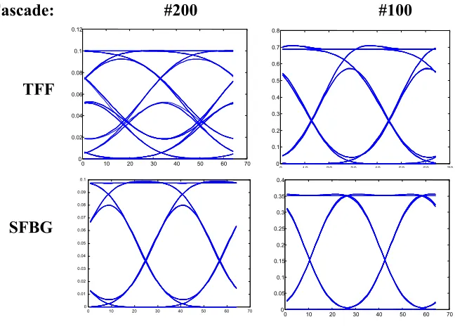
parameters. The effect of these misalignments to the overall performance of these two different types of cascaded filters is estimated here. We consider here a series of filters with central operating wavelengths uniformly distributed within a given symmetrical range of total misalignment. For a number of uniformly misaligned filters in the range of [-0.1nm, 0.1nm] around the central wavelength of 1550nm the EOP is estimated as a function of this number (Figure 1.8). After a number of 200 cascades the EOP for the Bragg grating is only ~1 dB in contrast with TFF case where the penalty approaches the value of 5 dB. Indicatively, Figure 1.9 shows the eye diagrams for both filters for the cascade number of 100 (Fig. 1.9(a)) and 200 (Fig. 1.9(b)).
Figure 1.9 Indicative eye-diagrams for Bragg grating and TFF
Based on the above results, is clear the great potential of the novel specially designed Bragg grating based filters (SBG), compared to the inherently MPF type and dispersive TFF. With the stringent filter specifications for DWDM systems in high bit-rate applications, the choice of SBG would be a much more favorable solution compared to today’s competitive TFF technology.
0 10 20 30 40 50 60 70 0
0.01 0.02 0.03 0.04 0.05 0.06 0.07 0.08 0.09 0.1
0 10 20 30 40 50 60 70
0 0.02 0.04 0.06 0.08 0.1 0.12
0 10 20 30 40 50 60 70
0 0.1 0.2 0.3 0.4 0.5 0.6 0.7 0.8
0 10 20 30 40 50 60 70
0 0.05 0.1 0.15 0.2 0.25 0.3 0.35 0.4
TFF
SFBG
[image:28.595.135.459.277.511.2]1.7 Bragg gratings based OADMs
Four-port devices that Add and/or Drop a particular channel are of great importance for optical networks. They can be used as simple components, which serve a single subscriber in a node of an optical network, or as building blocks of more complex modules such as optical cross connects and switch matrices. Simple OADM configurations, using the unique spectral characteristics of Bragg gratings, appear to be very promising solutions intended to find applications in DWDM systems.
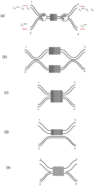
A number of different four-port OADM configurations have been proposed. The simplest one, which makes direct use of the reflection properties of a Bragg grating written in a single mode fiber, is the well-known configuration with the two optical circulators (OCs) [1.19] shown schematically in Figure 1.10(a). This OADM implementation is frequently used as a benchmark in the sense that it provides excellent crosstalk performance and negligible back reflections. In addition, the reflection and dispersion characteristics of the OADM are identical to the ones of the grating. However, it should be stressed that because of the circulators this OADM suffers from relatively high insertion loss (~1dB), it is bulky and expensive and cannot be easily integrated. It has been identified and realized that in future broadband communication networks WDM component’s volume or alternatively ‘component’s volume per Gb/s per WDM Channel [m3 –per- Gb/s –per- #Channel]’ becomes increasingly important parameter in commercial dence WDM systems and thus the systematic employment of bulky and expensive components cannot survive in the future. [1.20]
Figure 1.10 a) Circulator based OADM and explanation of the Add/Drop operation of a particular channel., b) Mach-Zehnder OADM configuration, (c) Symmetrical Coupler (SFC) OADM, d)Asymmetrical Coupler based OADM with Bragg grating in one waveguide only, e) Tilted Bragg grating based OADM
(a)
(b)
(c)
(d)
Perfectly matched MZI-based OADMs, with identical gratings in each arm, can potentially result in an ideal performance, better than the one of OC-based OADMs, since they show no backreflections and need no extra components, i.e. circulators or isolators. Additionally they can provide very low insertion losses (~0.1dB) and they can be fully integrated. However, grating mismatches and interferometer-arm imperfections compromise the OADM performance severely, resulting in strong backreflections and spectral distortions. In this case, careful post-processing and trimming is required. In addition, two extra isolators are quite likely to be required at the two input ports to avoid the deleterious effects of backreflections, making the total extra-component count equal to the OC-based devices.
devices will be to eliminate the sensitivity to environmental factors of vibrations, temperature changes and humidity.
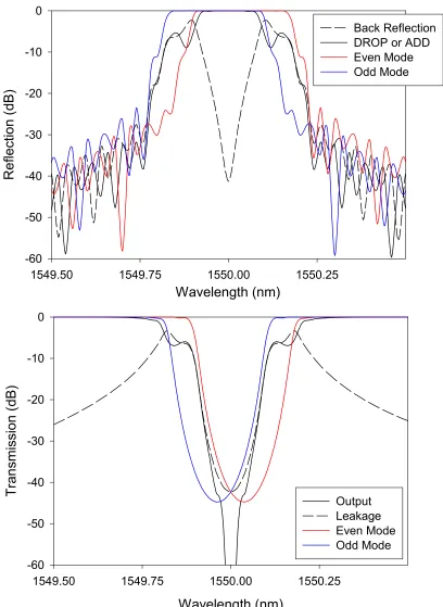
The third general category of Bragg grating based OADMs includes those based on asymmetric Bragg couplers [1.32-1.34]. In this case, a Bragg grating is used to contra-directionally couple light between two otherwise dissimilar uncoupled waveguides. In this geometry there are, in general, three types of interactions between the two lower order (even and odd) modes, involving even-even (e-e), odd-odd (o-o) eigenmode self-coupling as well as even-odd (e-o) eigenmode resonant cross-coupling. This results in a maximum of three reflection peaks appearing in the drop- and add-port spectra, as well as, strong backreflections in the input port. The relative strength of these peaks can be controlled by careful grating design.
resulting in a tight and restrictive relation between back reflections, bandwidth and minimum channel spacing [1.34].
Finally, another non-interferometric OADM configuration (see Figure 1.10(e)), based on a null coupler (with zero coupling) with a tilted grating in its waist, has been recently reported by Kewitsch et al. [1.33]. Null couplers are comprised of two dissimilar waveguides brought gradually into close proximity and finally in contact to form the waist. The devices are actually based on adiabatic mode transformation [1.35] taking place along the coupler arms and their waist. A short period UV-written tilted grating can provide resonant contra-directional coupling and add/drop function [1.6, 1.33]. A non-optimised null coupler device, however, will exhibit the same performance limitations as the other devices of this category, namely, a maximum of three reflection peaks at the drop- and add-port spectra, as well as, strong backreflections at the input port. In addition to OADMs, null couplers have also been excited with propagating flexural acoustic waves and successfully used for the implementation of other high quality fibre components, such as frequency shifters and switches [1.35]. With properly optimized characteristics of the null coupler and the employed tilted grating this device can exhibit theoretically superior characteristics [1.6] with a spectral response identical that of the employed Bragg grating, as will be described in Chapter 3
The performance of all these Bragg grating based OADM configurations and the requirements for optical isolators or circulators are concluded in the Table1.1 below.
Insertion
Loss reflections Back Spectru Drop-m Peaks
Add-Spectrum
Peaks
No of
Isolators Circulators No of
Circulator Based High Negligible 1 1 - 2
Interferometric
MZI (Ideal) Low Negligible 1 1 - -
MZI (Non-Ideal) Low High 1 1 2 -
Symmetric Coupler Low High 1 1 2 -
Frustrated Coupler Low High 1 1 2 -
Non-Interferometric (Grating-Assisted Couplers)
Normal written BG Low High 3 3 2 -
1.8 References
[1.1] D. C. Johnson, K. O. Hill, F. Bilodeau, and S. Faucher, “New design concept for a narrowband wavelength-selective optical tap and combiner,” Electronics Letters, vol. 23, pp. 668-669, 1987.
[1.2] C. Dragone, “An NxN optical multiplexer using a planar arrangement of two star couplers,” IEEE Photon. Technol. Lett., vol. 3, pp. 812-815, 1991.
[1.3] M. K. Smit, C. van Dam, “PHASAR-based WDM -devices: principles, design and applications,” IEEE Journal of selected topics in Quantum Electronics, vol. 2, no. 2, pp. 236-250, Jun. 1996.
[1.4] Y. P. Li, C.H. Henry, E. J. Laskowski, H. H. Yaffe, “Fourier transform based optical waveguide filters and WDM’s,” in OFC’96 Tech. Dig., vol. 2, pp. 97-98, 1996.
[1.5] M. A. Scobey, D. E. Spock, “Passive DWDM components using Microplasma optical interference filters,” in OFC’96 Tech. Dig., vol. 2, pp. 242-243, 1996.
[1.6] C. Riziotis, M. N. Zervas, “Design considerations of optical Add-Drop filters based on grating assisted mode conversion in null couplers,” IEEE/OSA Journal of Lightwave Technology, vol. 19, no. 1, pp. 92-104, Jan. 2001.
[1.7] M. Kuznetsov, N. M. Froberg, S. R. Henion, C. Reinke, C. Fennelly, “Dispersion-induced power penalty in fiber-Bragg-grating WDM filter cascades using optical preamplified and non-preamplified receivers,” IEEE Photonics Technology Letters, vol. 12, no.10, pp. 1406-1408, October 2000.
[1.8] A. V. Oppenheim and R. W. Schafer, Digital Signal Processing, Englewood Cliffs, NJ: Prentice-Hall, 1975.
[1.9] G. Lenz, B. J. Eggleton, C. R. Giles, C. K. Madsen, R. E. Slusher, “Dispersive properties of optical filters for WDM systems,” IEEE J. Quantum Elec., vol. 34, no. 8, pp. 1390-1402, 1998.
[1.10] Y. Hida, Y. Hibino, M. Itoh, A. Sugita, A. Himeno and Y. Ohmori, “Fabrication of low-loss and polarization-insensitive 256-channel arrayed-waveguide grating with 25 GHz spacing using 1.5% ∆ waveguides,” Electron. Lett., vol. 36, pp. 820-821, 2000.
[1.11] K. Okamoto, “Recent progress of integrated optics planar lightwave circuits,” Optical and Quantum Electronics, vol. 31, pp. 107-129, 1999.
[1.12] C. R. Giles, M. Spector, “The wavelength Add/Drop multiplexers for lightwave communication networks,” Bell Labs Technical Journal, pp. 207-229, Jan-Mar. 1999.
[1.13] Y. Hibino, “Passive optical devices for photonic networks,” IEICE Trans. Commun., vol. E83-B, no. 10, pp. 2178-2190, Oct. 2000.
[1.14] M. E. Vieira Segatto, G. D. Maxwell, R. Kashyap, J. R. Taylor, “High-speed transmission and dispersion characteristics of an arrayed-waveguide grating,” Optics Communications, vol. 195, pp. 151-157, Aug. 2001.
[1.15] K. O. Hill, B. Maro, F. Bilodeau, D. C. Johnson, J. Albert, “Bragg gratings fabricated in monomode photosensitive optical fiber by UV exposure through a phase mask,” Appl. Phys. Lett., vol. 62, pp. 1035-1037, 1993.
[1.16] W. H. Loh, M. J. Cole, M. N. Zervas, S. Barcelos, R. I. Laming, “Complex grating structures with uniform phase masks based on the moving fiber-scanning technique,” Opt. Lett., vol. 20, no. 20, pp. 2051-2053, Oct. 1995.
[1.18] M. Ibsen, P. Petropoulos, M. N. Zervas, R. Feced, “Dispersion-free fiber Bragg gratings,” paper MC1, Optical Fiber Communication Conference, OFC’2001, Anaheim, March 2001,
[1.19] K. P. Jones, M. S. Chadry, D. Simeonidou, N. H. Taylor, P. R. Morkel, “Optical wavelength add-drop multiplexer in installed submarine WDM network,” Electronics Letters, vol. 31, no. 24, pp. 2117-2118, Nov. 1995.
[1.20] Private communication with Dr. B. Garrett, Nortel Networks at PHOTON-Project Meeting, University College London, London, April, 2001
[1.21] T. Erdogan, T. A. Strasser, M. A. Milbrodt, E. J. Laskowski, C. H. Henry, and G. E. Kohnke, “Integrated-Optical Mach-Zehnder add-drop filter fabricated by a single UV-induced grating exposure,” Applied Optics, vol. 36, pp. 7838-7845, 1997.
[1.22] F. Bilodeau, K. O. Hill, B. Malo, D. C. Johnson, J. Albert, “High-return-loss narrow-band all-fibre bandpass Bragg transmission filter,” IEEE Photonics Technology Letters, vol. 6, no. 1, pp. 80-82, Jan. 1994.
[1.23] R. Kashyap, G. D. Maxwell, and B. J. Ainslie, “Laser-Trimmed four-port bandpass filter fabricated in single-mode photosensitive Ge-doped planar waveguide,” IEEE Photonics Technology Letters, vol. 5, no. 2, pp. 191-194, Feb. 1993.
[1.24] F. Bilodeau, D. C. Johnson, S. Theriault, B. Malo, J. Albert, K. O. Hill, “An all-fiber dense-wavelength-division multiplexer/demultiplexer using photoimprinted Bragg gratings,” IEEE Photonics Technology Letters, vol. 7, no. 4, pp. 388-390, Apr. 1995.
[1.26] K. Bakhti, P. Sansonetti, C. Sinet, L. Gasca, L. Martineau, S. Lacroix, X. Daxhelet, F. Gonthier, “Optical add-drop multiplexer based on UV written Bragg gratings in a fused 100% coupler,” Electronics Letters, vol. 33, no. 9, pp. 803-804, Apr. 1997.
[1.27] D. Marcuse, Theory of Dielectric Optical Waveguides, Chapter 7, Academic Press, New York, 1991.
[1.28] R. R. A. Syms, “Optical directional coupler with a grating overlay,” Applied Optics, vol. 24, no. 5, pp.717-726, Mar. 1985.
[1.29] J.-L. Archambault, P. St. J. Russell, S. Barcelos, P. Hua, L. Reekie, “Grating frustrated coupler: A novel channel-dropping filter in single-mode optical fiber,” Optics Letters, vol. 19, pp. 180-182, 1994.
[1.30] P. Yeh, H. F. Taylor, “Contradirectional frequency-selective couplers for guided wave optics,” Applied Optics, vol. 19, no. 16, pp. 2848-2855, Aug. 1980.
[1.31] N. Imoto, “An analysis for contradirectional-coupler-type optical grating filters,” Journal of Lightwave Technology, vol. LT-3, no. 4, pp. 895-900, 1985.
[1.32] L. Dong, P. Hua, T. A. Birks, L. Reekie, P. St. Russell, “Novel add-drop filters for Wavelength-Division Multiplexing optical fibre systems using a Bragg grating assisted mismatched coupler,” IEEE Photonics Technology Letters, vol. 8, no. 12, pp. 1656-1658, Dec. 1996.
[1.34] T. Erdogan, “Optical add-drop multiplexer based on asymmetric Bragg coupler,” Optics Communications, vol. 157, pp. 249-264, Dec. 1998.
CHAPTER 2
Analysis and Modelling of Bragg Grating
Assisted Waveguide Devices
2.1 Introduction
This Chapter describes the theoretical mathematical analysis and the simulation method for arbitrarily shaped coupled waveguide structures, and develops the complete formulation for the analysis and simulation of a non-uniform Bragg grating in a two-mode structure. Combination of the two formulations is implemented [2.1] in order to calculate the full spectral response of any device based on a grating based coupled waveguide structure.
The widely established approach for the simulation of waveguide devices and grating assisted coupled waveguide devices is probably the Coupled Mode Theory (CMT) [2.2, 2.3] which combines a deep physical and intuitive insight into the problem together with a much greater computational simplicity compared to other methods such as Finite Difference (FD) and Finite Element (FE) Beam Propagation Methods (BPM) [2.4, 2.5].
non-orthogonal CMT [2.7]. The first one is a simple intuitive approximation, which can model quite accurately devices with weakly coupled waveguides. The later is more complicated and can model a wider variety of problems involving dissimilar waveguides for even the strongly coupled case [2.8-2.10]. Strong coupled mode theory has been also applied to grating assisted filters and a discussion for the application of this theory can be found in [2.3, 2.5]. A very strong debate developed for over a decade during 1980s regarding these two theories. An extensive discussion and analysis about the debate, the accuracy and the applications of the two formulations can be found in the references [2.3] and [2.8].
A more rigorous and general coupled-mode approach uses the exact composite modes –normal modes- of the waveguide structure instead the approximation of the superposition of the individual waveguide modes. This approach is much more accurate and can be applied equally effectively in the strongly coupled case since the normal modes are calculated directly taking into account the exact shape of the structure, without considering any approximations. The local normal mode analysis in conjunction with the step transition model [2.11] has been applied by Burns & Milton and Yajima [2.12, 2.13] in the problem of strongly coupled branching waveguides. The power transfer mechanism and mode conversion between the local normal modes is described by the step transition model giving this way a quantitative estimation of the power propagating along the waveguide structure. The method is computationally more intensive than the traditional CMT since for the modeling of a device is required the solution of the dispersion equation at each step of the propagation simulation and the calculation of modal overlap integrals. This method has been applied for the modeling of strongly coupled tapered structures and resulted in very good agreement with the experimental findings [2.14].
sections present the mathematical analysis and the algorithmic implementation of the model.
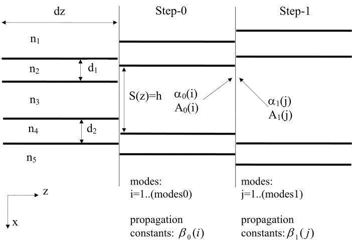
[image:42.595.120.471.333.582.2]2.2 Local normal mode analysis and step transition model
Figure 2.1 demonstrates the working principle of the model. An arbitrary continuous coupler structure –with refractive indices distribution and geometrical characteristics as described in the Figure- is divided in a number of discontinuous abrupt steps of length dz. Each step forms a parallel, five-layer waveguide structure and the normal modes are calculated by solving the dispersion equation of the 5-layer structure, as described in the next section. The propagation constants of the #modes0 normal modes at step-0 and #modes1 normal modes at step-1 are β0( )i , β1( )j respectively.
Figure 2.1 Schematic and parameters of the step transition model
The power transfer between the normal modes of the two successive step sections is
calculated at each interface. The amplitudes A1(j), and phases α1(j) at step-1 are
calculated as a function of the amplitudes A0(i), and phases α0(i) at step-0.
n1
n2
n3
n4
n5
z
d1
d2
S(z)=h
Step-0 Step-1
x
α0(i)
A0(i) αA1(j)
1(j) dz
modes: i=1..(modes0) propagation constants: β0( )i
All the calculations are based on a five-layer planar structure with step refractive index profile. For channel waveguides geometry the 3D problem can be reduced to a 2D problem through the effective index method and can be treated this way with the same model.
2.2.1 Dispersion equation for the five layer waveguide structure
In the analysis in this Chapter we consider for simplicity only the propagation of the Transverse Electric (TE) modes. All the waveguide structures and devices in this thesis are modeled also for the TE case. However, it should be stressed that under the weak guiding approximation the analysis and the results for the TE case can be applied with very good approximation to the TM case.
The TE electric field distribution for a five-layer waveguide can be expressed as follows:
e
E e x
E e E e x d
E e E e d x d h
E e E e d h x d h d
E e d h d x
y
k x
jk x jk x
k x k x
jk x jk x
k x
=
−∞ < <
+ < <
+ < < +
+ + < < + +
+ + < < + ∞ + − − + − − + − − − 1
2 2 1
3 3 1 1
4 4 1 1 2
5 1 2
1 1 2 3 3 4 4 5 0 0 (2.1) where
k n k i
k
i = − i =
= β ω µ ε
2
0 2
0 2
0 0
1 2 3 4 5
( ) , , , ,
(2.2)
For the TE modes we have ez =0, hy =0. From the Maxwell equations we derive
also that ez =0, ex =0 and:
The boundary conditions demand that ey (and thereby automatically hx) and x ey ∂ ∂
(and
thereby hz) be continuous at the boundaries x=0, d1, d1+h, d1+h+d2. By these
continuity conditions the eigenvalue equation can be obtained and is given by the expression:
{( ) ( ) tan( )} {( ) ( ) tan( )}
exp( ){( ) ( ) tan( )}
{( ) ( ) tan( )}
k k k k k k k d k k k k k k k d
k h k k k k k k k d k k k k k k k d
1 3 2 1 3 2
2
2 1 3 5 4 3 5 4
2
4 2
3 3 1 2 1 3 2
2
2 1
3 5 4 3 5 4
2
4 2
2
0
+ + − ⋅ + + −
− − − + + ⋅
− + + =
(2.3)
Using numerical methods this dispersion equation is solved at each step of the structure
and the propagation constants β of all the normal modes at the particular step are
calculated.
2.2.2 Step-wise approximation of waveguide structures
Next we describe briefly the model for the case of propagation of transverse electric (TE) guided modes in a multimoded coupled waveguide structure.
The guided-mode’s TE electric fields can be expressed as:
ey =E(z).Ψβ(x,z)exp(−j⋅a(z)), a(z)=βz+ϕ (2.4)
where E(z) is the real amplitude at the position z, Ψβ(x,z) the real electric field
distribution which corresponds to the propagation constant β and ϕ a phase constant
in a general case. At each step along the structure the propagation constants of the normal modes are obtained form the solutions of the eigenvalue equation for the TE modes. The computational core of the step transition model is based on the calculation of mode conversion and power transfer which takes place at the interface formed between the two successive abrupt steps 0 and 1 (Figure 2.1). The formulation which describes the power transfer of the #modes0 normal modes at step 0 to the #modes1 normal modes at step 1 originates from the expressions of boundary conditions of
continuity for the fields eyand hx .
The amplitude coefficient and phase of the j (j=1...modes1) mode - which corresponds
to propagation constant β1( )j - at step-1 is given [2.3] by the expression:
∑
=
− ⋅
⋅ =mod 0
1
1 0 0
1( ) ( , ) () cos( () ( ))
es i j a i a i A j i c j
A
(2.5)
∑
∑
= = ⋅ ⋅ ⋅ ⋅ = mod 01 0 0 0 mod 1 0 0 1 )) ( cos( ) ( ) , ( )) ( sin( ) ( ) , ( )) ( tan( es i es i i a i A j i c i a i A j i c j
a (2.6)
c i j i j
j j
j i
i i
I i j
I i i I j j
i j
i i j j
( , ) ( ) ( )
( ( ) ( )
( ) ( ) ( ) ( )
( ( ), ( ))
( ( ), ( )) ( `( ), ( )) =
+
+ +
⋅
2 0 1
0 1
0 1
0 1
0 1
0 0 1 1
0 1
0 0 1 1
β β
β β
β β
β β
β β
β β β β (2.7)
The overlap integrals are estimated according to the formula:
Ii j c i d i i x j x dx c d
c d( ( ),β β ( ))= βc( )( )⋅ βd( )( )⋅ , , = ,
−∞ +∞
∫
Ψ Ψ 0 1 (2.8)For convenience, the amplitude coefficient on the above expressions is the normalized real amplitude A(z) of the mode, defined as the ratio of the mode amplitude in the
presence of mode conversion to that amplitude which corresponds to unity power. After these computations at each discontinuity of the structure the ‘new’ local normal
modes at step-1 are propagated along the finite length dz of the step. The mode propagation along the length of a waveguide structure is simulated by iterative calculations of transmitted modes’s amplitude and phase, as described in Equations 2.5-2.7. A pseudoalgorithmic implementation of the procedure is presented in Appendix 2.A.
2.3 General analysis of a non-uniform Bragg grating
In this section we develop and present the theory for the calculation of the spectral response of a nonuniform–apodized Bragg grating. The treatment is very general and accurate because it takes into account the two (even and odd) forward and the two backward propagating normal modes of the grating and was applied for first time by Weber [2.15] for the special case of a uniform grating.
Figure 2.2 Model for the calculation of spectral response of a Non-Uniform Grating
Initially, the non-uniform Bragg grating is divided into #n uniform step-regions
[Lk, Lk+1], where k = 0, …(n, -1). Let us assume that in the grating region, Fi (z) (i=1,2)
are the amplitudes of the two forward propagating normal modes and Gi (z) are the
amplitudes of the two backward propagating normal modes as illustrated at the schematic model in Figure 2.2.
The electric field in the grating can be expressed as:
E F z e G z e x
F z e G z e x e
g
j z j z
j z j z j t
g g
g
g g
g
= +
+ +
− +
− +
{ ( ) ( ) ) ( )
( ) ( ) ) ( )}
1 1
1 1
1 1
1
2 2
2
β β
β
β β
β ω
Ψ
Ψ (2.9)
L0 = 0 Ln = L
GRATING
F1(0)
F2(0)
G1(0)
G2(0)
F1(L)
F2(L)
G1(L)
G2(L)
z
where Ψβgi are the normal modes of the refractive index-averaged waveguide, because
of the grating perturbation, which correspond to the propagation constants βgi i=1,2 at
the waist waveguide. Real grating’s fabrication capabilities [2.16] allow us to assume always that the average refractive index of the perturbed waveguide is the same as that of the waveguide outside the grating section, simplifying this way the problem. The normal modes in the above equation are normalized according to the following equation:
Ψβ Ψβ ωµ
β δ
gi x gj x dx i j
gi ij
( )⋅ ( ) = , = ,
−∞ +∞
∫
2 0 1 2 (2.10)The wave equation for the electric field component is the following:
∇2 + 2 0[ ( )+∆ ( , )] =0
g r
r
g x x z E
E ω µε ε ε (2.11)
where εr is the relative permittivity and ∆εr, is the perturbation of the dielectric
permittivity because of the grating presence , which is periodic in the z-direction with zero average over a period. This perturbation can be expanded in Fourier series:
∆ε ∆ε Λ
π
r m
jm z
m
x z x e
( , )= ( )⋅ −
≠
∑
20
(2.12)
where Λ is the period of the perturbation. In our analysis we retain only the
fundamental harmonic (m=1)
dF
dz jk G z e jk G z e dF
dz jk G z e jk G z e dG
dz jk F z e jk F z e dG
dz jk F z e jk F z e
j z j z
j z j z
j z j z
j z j z
1
11 1 2
12 2
2
12 1 22 2 2
1
11 1 2
12 2
2
12 1 22 2 2
1 1 2
1 2 2
1 1 2
1 2 2
= − − = − − = + = + + + − − + − + − ( ) ( ) ( ) ( ) ( ) ( ) ( ) ( ) ( ) ( ) * * ( ) * ( ) * ∆ ∆ ∆ ∆ ∆ ∆ ∆ ∆ ∆ ∆ ∆ ∆
β β β
β β β
β β β
β β β
(2.13)
where ∆βiare the phase detunings from the Bragg condition:
∆βi =βgi −KB =βgi −π/Λ (2.14)
and kij the three coupling coefficients:
∫
∫
∫
Ψ ∆ = Ψ Ψ ∆ = = Ψ ∆ = + + + xb xa xb xa xb xa dx x x k dx x x x k k dx x x k g g g g ) ( ) ( 4 ) ( ) ( ) ( 4 ) ( ) ( 4 2 1 0 22 1 0 * 21 12 2 1 0 11 2 2 1 1 β β β β ε ωε ε ωε ε ωε (2.15)The integration bounds xα, xb define the spatial transverse extension of the grating.
The system of differential equations can be rewritten in the form:
S z
jk e jk e
jk e jk e
jk e jk e
jk e jk e
j z j z
j z j z
j z j z
j z j z
( ) ( ) ( ) * * ( ) * ( ) * = − − − − + + − − + − + − 0 0 0 0 0 0 0 0 11 2 12 12 22 2
11 2 12
12 22 2
1 1 2
1 2 2
1 1 2
1 2 2
∆ ∆ ∆
∆ ∆ ∆
∆ ∆ ∆
∆ ∆ ∆
β β β
β β β
β β β
β β β
(
2.17)and the vectors F, G are defined as
= = ) ( ) ( ) ( ) ( ) ( ) ( 2 1 2 1 z G z G z G and z F z F z
F (2.18)
Generally we can relate the vectors F, G at the position z= Lb with the vectors F, G at
z= La using the transfer matrix P L L( , ) : a b
⋅ = ) ( ) ( ) , ( ) ( ) ( a a b a b b L G L F L L P L G L F (2.19)
The matrix P L L( , ) is the solution of the system and can be calculated by numerical a b
integration of the differential equations system (2.16) between La,Lb. However, by
making use of the special structure of the matrix S(z) it can be proved [2.15] that the solution matrix can be calculated analytically using the following form:
P L L( , ) exp(a b = S L1∆ ) exp(S L2∆ ) , ∆L L= b−La (2.20)
where S j j j j 1 1 2 1 2
0 0 0
0 0 0
0 0 0
0 0 0
and
S S L S
j jk e jk e
j jk e jk e
jk e jk e j
jk e jk e j
a
j z j z
j z j z
j z j z
j z j z
z La
2 1
1 11
2
12
2 12 22
2 11 2 12 1 12 22 2 2 0 0 0 0
1 1 2
1 2 2
1 1 2
1 2 2
= − = − − − − − − + + − − + − + − = ( ) ( ) ( ) * * ( ) * ( ) * ∆ ∆ ∆ ∆ ∆ ∆ ∆ ∆ ∆ ∆ ∆ ∆ ∆ ∆ ∆ ∆ β β β β
β β β
β β β
β β β
β β β
(2.22)
The exponential of the matrix S2 can be easily calculated by finding the equivalent third
degree polynomial and the eigenvalues of matrix S2 [2.15].
Using the above formulation we can calculate the response of a non-uniform grating by dividing the structure into many segments and estimating the solution matrix for each one. Then it can be proved that the total solution matrix for the whole non-uniform grating structure can be expressed as:
Ptotal( , )0 L = P L( n−1, )Ln ⋅P L( n−2,Ln−1) ... ( , )⋅ ⋅P L L1 2 ⋅P L L( , )0 1 (2.23)
and finally ⋅ = ) 0 ( ) 0 ( ) , 0 ( ) ( ) ( G F L P L G L F
total (2.24)
The total solution matrix can be expressed in the form:
4 4 2 2 2 2 2 2 2 2 ) ( ) ( ) ( ) ( ) , 0 ( x x GG x GF x FG x FF
total P P
P P L P
= (2.25)
The grating spectral response can now be calculated from Equation (2.24).
normal modes F(0) and G(L), we calculate the output normal modes F(L) and G(0). From Equation (2.24) we have:
(
)
⋅ ⋅ − ⋅ = ⋅ ⋅ − ⋅ ⋅ + ⋅ = ⇔ ⋅ ⋅ − ⋅ = ⋅ + ⋅ = ⇔ ⋅ + ⋅ = ⋅ + ⋅ = − − − − − − ) 0 ( ) ( ) 0 ( ) 0 ( ) ( ) 0 ( ) ( ) 0 ( ) ( ) 0 ( ) 0 ( ) 0 ( ) ( ) 0 ( ) 0 ( ) ( ) 0 ( ) 0 ( ) ( 1 1 1 1 1 1 F P P L G P G F P P L G P P F P L F F P P L G P G G P F P L F G P F P L G G P F P L F GF GG GG GF GG GG FG FF GF GG GG FG FF GG GF FG FFwhich after some minor manipulations leads to the expression: 1 4 2 1 2 1 4 4 2 2 1 2 2 1 2 2 1 2 2 1 1 4 2 1 2 1 ) ( ) ( ) 0 ( ) 0 ( ) ( ) ( ) ( ) ( ) 0 ( ) 0 ( ) ( ) ( x x x GG x GF GG x GG FG x GF GG FG FF
x G L
L G F F P P P P P P P P P G G L F L F ⋅ ⋅ − ⋅ ⋅ ⋅ − = − − − − (2.26)
The phase and the amplitude information of the normal modes are contained in this complex representation.
2.4 Analysis of the composite grating-coupler structure
2.4.1 Excitation of the input waveguides
When a multimode structure is excited by an input field Ψ(i)(x) then the excitation
amplitude apof the pth normal mode Ψp(x)in the multimode section is given by the
overlap integral between the two modes:
1/2
2 ) ( ) ( ) ( ) ( Ψ Ψ ⋅ Ψ =
∫
∫
∞ + ∞ − +∞ ∞ − dx x dx x x a p p ip (2.27)
The fraction of incident power excited in each mode fp can be calculated as:
dx x dx x a f i p p p 2 ) ( 2 ) ( ) (
∫
∫
∞ + ∞ − +∞ ∞ − Ψ Ψ ⋅= . (2.28)
2.4.2 Calculation of the response of the composite structure
Lets consider that in the multimode structure, #N normal modes are propagating. At the output ports #1 and #2 the relative amplitude and the phase of those modes are
Αi, αi, i=1 2, ,...,N. Let E x E x1( ), 2( ) are the electric field distributions of the
fundamental modes of the individual waveguides 1 and 2 respectively.
The total electric field at the position L of the structure is:
∑
= ⋅ − ⋅ Ψ ⋅ = Ε N i a j i itot x A x e i
1
) ( )
where Ψi(x), i=1,2,...,N are the electric field distributions of the respective normal
modes.
Figure 2.3 Output waveguides