AbstractOrganic microcavities provide unique properties that are highly advantageous for designing microlasers, but lack in efficient ways to directly integrate electrodes able to drive high currents. The introduction of thin, patterned metal films, lead-ing to the formation of local Tamm-plasmon-polariton states, has been recently demonstrated as a possible route to preserv-ing coherence in the presence of significant optical loss. Here, periodic micron-scale gratings of silver are embedded into a high-quality organic microcavity, creating a crystal-like photonic potential structure. Despite strong absorption of metallic lay-ers, these structures readily lase upon optical excitation. In that case, the above threshold emission originates not from isolate metal-free areas but instead from phase-locked supermodes spreading over several grating periods. Remarkably, in-plane coherence can spread even further when decreasing the grat-ing period, covergrat-ing distances of more than 50 µm and more than 10 metal stripes. One- and two-dimensional gratings with varying periods are investigated using tomographic scanning of thek-space emission fine structure, which exhibits a strong dependence on the grating geometry. These results support the fabrication of highly customizable organic microlasers with tailored in-plane coherence, and demonstrate the coexistence of extended coherence and optical loss.
Phase-locked lasing in one- and two-dimensionally patterned
metal-organic microcavities
Andreas Mischok
1,2,*, Mona Kliem
1, Robert Br ¨
uckner
1, Stefan Meister
1, Hartmut Fr ¨
ob
1,
Malte C. Gather
2, Karl Leo
11. Introduction
Organic microlasers promise a range of useful applications and are therefore of considerable interest in current re-search [1, 2]. However, the realization of an electrically pumped solid state organic laser remains elusive and is still regarded as the ”holy grail“ of the field. While considerable effort is directed towards highly efficient conductive as well as emissive organic materials [3] and polariton lasing [4–6], identifying efficient electrode designs is equally important. Most cavity designs for organic microlasers utilize either distributed feedback on a pre-structured grating or verti-cal feedback by sandwiching the active layer in between highly reflective distributed Bragg reflectors (DBRs) [7], with the latter having advantages in device footprint and offering surface emission. Such vertical microcavities effi-ciently confine light between the dielectric mirrors, leading to a parabolic dispersion of cavity photons, but usually do not offer a direct way of electrical contacting. By introduc-ing thin, highly conductive metal films into such cavities,
their photonic potential is altered. As cavity photons or po-laritons interact with plasmons in the metal, they experience a jump in phase, leading to the creation of red-shifted states known as Tamm-plasmons-polaritons (TPPs) [8, 9] which have been shown to have the potential for high optical qual-ity [10, 11]. In devices with extended metal layers, these have found a multitude of use for lasers [11, 12], thermal emitters [13], and exciton-polariton coupling [14, 15] as well as sensing and photodetection [16, 17]. Patterning this metal layer however, leads to a local shift in cavity poten-tial [18] and enables strong lateral confinement [19–21], but also surprisingly facilitates a macroscopic in-plane coher-ence [22] where the coherent mode is spread across several periods of a metal grating. When coherent emission couples between individual spots of lasing or polariton condensates, their phases interlock [22–28] and complex supermodes are formed, exhibiting an intricate fine structure in real-,k-, and phase-space.
1Dresden Integrated Center for Applied Physics and Photonic Materials, Technische Universit ¨at Dresden, N ¨othnitzer Strasse 61, 01187 Dresden, Germany 2Organic Semiconductor Centre, SUPA, School of Physics and Astronomy, University of St. Andrews, North Haugh, St. Andrews KY16 9SS, UK
Ag 1.93
V (eV)
p
x
Ag
1.85
DBR
p
DBR
DBR Cavity (a)
V0 p
675 650
W
avelen
gth (nm)
625 600
kx ky
Extended Cavity States
Confined TPP States (c)
Angle (deg)
0 20 40
-20 -40
W
avelen
gth (nm) 640
660 620 (b)
680 (1)
(2)
(2) Extended
Cavity States
Confined TPP States
p=5μm p=4μm
Ag
Intensity (a.u.) 10 10
-1 1 (1)
�
x y
[image:2.595.61.534.66.284.2]Lx
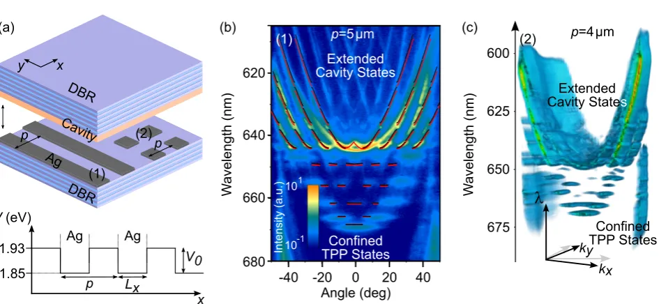
Figure 1 (a) Sample schematic of the microcavity with patterned metal layers. On top of the bottom DBR, a thin layer of silver is patterned to obtain either 1D stripe- (type (1)) or 2D dot- (type (2)) and hole- gratings. The lower part shows the photonic potential in the patterned microcavity, where potential wells are created at the position of the silver structures. (b) Dispersion of a stripe-grating microcavity red inkx- direction. Introducing a 1D grating of type (1) (compare (a)), with a period of 5 µm leads to the formation of trapped discrete Tamm-plasmon-polariton (TPP) states (>645nm) and a Bloch-like band structure (<645nm). Bright (dark) red lines show the calculated band structure of the device in TE (TM) polarization. (c) Dispersion tomography of a dot-grating microcavity (type (2)) with a period of 4 µm, showcasing fully confined TPP states below and extended Bloch states above the potential barrier (at
≈645nm).
Here, we introduce both one- and two-dimensional metal gratings into an organic microcavity and vary the period of these structures to systematically study the influ-ence on above-threshold emission. In all cases, we observe lasing from phase-locked states spanning over many peri-ods. Surprisingly, coherence is retained for various types of gratings, even when the majority of the sample surface is covered by metal. Utilizing dispersion tomography, we investigate thek-space fine structure of such phase-locked lasing modes for one- and two-dimensional gratings and find an enhanced spread of coherence compared to unpatterned devices.
2. Methods and Materials
The structure of the investigated device is schematically drawn in Figure 1 (a). The design comprises two DBRs with 10.5 alternatingλ/4 layers of TiO2(n≈2.15) and
SiO2(n≈1.45, raw materials purchased from Prof.
Feier-abend GmbH) sandwiching an organic activeλ/2 layer of
Tris-(8-hydroxyquinolinato)-aluminium (Alq3, purchased
from Sigma Aldrich) doped by 2 wt% with the laser dye Dicyanomethylene-2-methyl-6-p-dimethylaminostyryl-4H-pyran (DCM, purchased from Radiant laser dyes).
Between bottom DBR and organic cavity, a thin silver layer (≈30 nm) is deposited and patterned into (i) a one-dimensional periodic stripe grating (Fig. 1 (a), type (1)), (ii) a two-dimensional periodic square (Fig. 1 (a), type (2)) or (iii) hole grating with periods between 4 µm and 9 µm.
The interaction between cavity photons and the plasmonic metal layer now leads to the formation of TPP states [8, 9], where the highest energy TPP state is significantly red-shifted compared to the original cavity mode. Consequently, patterning the silver film leads to the formation of photonic potential wells [18] as depicted in the lower half of Fig. 1 (a), which are the building blocks to create one- and two-dimensional lattices [29].
Here, the oxide layers are deposited via electron-beam evaporation in a custom vacuum chamber at a base pressure of 10−6mbar and a partial oxygen pressure of 2×10⁻⁴mbar to prevent the formation of sub-oxides. The organic mate-rials are purified by vacuum gradient sublimation at least twice before they are deposited by thermal co-evaporation of matrix and dopant at a base pressure of 10−8mbar. To facilitate the metallic structures of interest, a negative pho-toresist (AZ nLOF2020 from MicroChemicals) is patterned using a SUESS MJB4 mask aligner to act as lift-off resist before subsequently depositing a 30 nm thick layer of silver on top of an adhesion layer of 2 nm gold. After lift-off, the organic layer and top DBR are deposited on the final silver structures.
The devices are investigated using angle-resolved micro-photoluminescence spectroscopy, with a high NA objective (NA=0.8, 63×) projecting the Fourier plane of the sample emission onto the entrance slit of an 0.6 m spectrometer equipped with a cooled charge-coupled device. For sam-ple excitation, either a cw laser diode at 405 nm (Coherent CUBE 405-50C) excites the matrix (Alq3), to record
pulse length at 2 kHz repetition, CryLas FDSS-532-Q2) excites the laser dye (DCM) directly and is used for both spontaneous and stimulated emission of the device.
For tomographic scanning along thekyaxis, the far field
lens is moved out of the optical axis to record higher in-plane angles (details see [30]). The final image is recreated using Mayavi [31].
3. Results
3.1. Dispersion in One- and Two-Dimensional
Gratings
Figure 1 (b) shows thekx- dispersion of aλ/2 microcavity
with 30 nm of silver patterned into stripes along they-axis, with a period of 5 µm (type (1)). The one-dimensional pho-tonic wires that are created by the silver stripes efficiently confine TPP states in red the observed x-direction [18] within potential wells of depthV0=80 meV. This strong
confinement results in discrete, flat modes in the dispersion, localized below the potential barrier at wavelengths greater than 645 nm. Above this barrier, photons travel freely be-tween adjacent metal-free areas, exhibiting a Bloch-like band structure of the extended cavity states. To confirm our observation, we calculate the Bloch bands via a modified Kronig-Penney model [18, 32]. Atky=0, the cavity energy
is given by:
E(k) =hc¯ q
k2
z+kx2≈E0+
¯
h2
2mphot
kx2, (1)
with ¯has the reduced Planck constant,cthe speed of light in the organic material, E0≈πhc/L¯ C the energy of the
fundamental cavity mode, the cavity length LC, and the effective mass of photonsmphot. In vertical microcavities,
photons and polaritons obtain an effective mass due to the vertical confinement between the mirrors, its value being on the order of 10−5times the free electron mass. When the cavity is detuned from the DBR design wavelength, as is inevitably the case in these metal-organic devices, this effective mass becomes dependent on the polarization of light. By considering cavity length and DBR penetration depth of the cavity photons [32, 33], we obtain values of
mphot,TE=1.06×10⁻³⁵kg andmphot,TM=1.02×10⁻³⁵kg.
The resulting values can be used to calculate the band struc-ture of the well-known Kronig-Penney model corresponding to the artificial potential structure created here. In Fig. 1 (b), this calculation is overlaid on the measured dispersion as bright (dark) red lines, representing the calculated bands in TE (TM) polarization. Both discrete, core-electron-like states below the potential barrier (at≈645 nm), as well as the extended, valence-electron-like bands above the barrier are well reproduced in the calculation. A further variation of periods in this structure is shown in the supporting informa-tion, Figure S1. While the dispersion perpendicular to the stripe orientation exhibits this rich structure, no confinement is observed in parallel direction red (data not shown here). As demonstrated previously for dielectric photonic wires
embedded in such cavities [30], dispersion parabolas appear inky-direction, with additional parabolic branches for the
corresponding discrete states at higherkx.
It is also important to note that the confined TPP states exhibit broader linewidths and in turn lower quality factors (<450) when compared to the above-barrier Bloch bands (600 - 1000). As the TPPs are highly localized on the metal while the above-barrier states mainly reside in the metal-free area, it becomes clear that the parasitic absorption of this metal layer limits the cavity photon lifetime and thus the quality factor here.
By comparison to the one-dimensional structure, the two-dimensional square dot grating leads to a full confine-ment of light. Figure 1 (c) shows a reconstructed tomo-graphic scan of the full dispersion in bothkxandky
direc-tions for such a device with a period of 4 µm. As light in TPP states is now essentially trapped at the position of a square metal dot, the dispersion exhibits fully flat discrete modes below the confining potential (again>645 nm), in bothkxandkydirections, according to [34]:
E(k)≈hc¯ r
π LC
+ π Lx
(qx+1) + π Ly
(qy+1), (2)
withLx,Ly andqx,qy as potential width and mode
num-ber inxandy-direction, respectively. Again, the behaviour above the barrier shows a Bloch-like band structure, now in two dimensions, albeit more difficult to resolve in the experiment.
Interestingly, the highest below-barrier states already show signs of cross-talk between different stripes, that is, they deviate from a completely flat dispersion and are able to travel in between different metal stripes without losing coherence. It is important to note that the observation of such a complex dispersion indicates the presence of a high degree of in-plane coherence in the spontaneous emission. This confirms the high quality of the cavity and the metal patterning.
A third type of patterning is also realized, namely the inverse of pattern type (2), i.e. a fully metal-covered bot-tom mirror with a square hole grating. For this structure, the dispersion is not fundamentally different from the dot pattern, although the degree of confinement in TPP states is naturally much lower. A clear difference with respect to the dot grating can be seen in their stimulated emission fine structure.
3.2. Stimulated Emission of Phase-Locked
States
Angle (deg)0 20 40 -20
-40
p=5μm
k=0
W
avelen
gth (nm) 640
660 620
(a) (b)
Confined TPP States Extended Bloch-like states
Lasing 2�-state
680
6μm
7μm
8μm
9μm
�-state
��-state
�-state
�-state
��-state
W
avelen
gth (a.u.)
p=6μm
Intensity (a.u.)
0 1
Intensity (a.u.) 10
10
-1 4
Angle (deg)0 20 40 -20
-40
Real-space distance (μm)-20-10 0 -30
-40 10 20 30 40
0 0.2 0.4 0.6 0.8 1.0
Intensity (a.u.) 0 0.2 0.4 0.6 0.8 1.0
0 0.2 0.4 0.6 0.8 1.0
p=5μm
p=7μm
p=9μm
approx. position of metal stripe
�-state
�-state
��-state
Amplitude Envelope
(c)
(d)
[image:4.595.56.536.60.271.2](e)
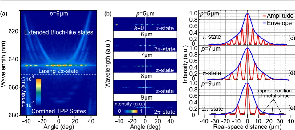
Figure 2 (a) Dispersion of a lasing2π-state in a stripe-grating microcavity (type (1)) atp=6.0µm. Due to the modified photonic potential, lasing starts as a supermode spanning several periods. (b) Lasing states at varying periods. By decreasing the period from 9 µm to 5 µm, thek-space separation of lasing antinodes increases while their individual width decreases - pointing towards a larger spread of coherence in real space. Please note that the color scale in (b) is linear while it is logarithmic in (a). (c)-(e) Real-space distribution of coherent emission. By Fourier-transformation of the far-field image, the coherent spatial extension of lasing states can be obtained. In each case, the lasing supermode is spread over several stripe periods, confirming the long-range coherence of the emission. For smaller periods (comparep=5µm (c), 7 µm (d), 9 µm (e)) the mode extension increases both in number of periods as well as in absolute distance.
While some systems show lasing from single confined re-gions created by patterning [12, 21, 22], in our system lasing always originates from a phase-locked supermode spanning a multitude of grating periods. Despite apparent optical loss induced by the silver structure, such an extended mode is consistently preferred over uncoupled lasing from individual stripes. In the investigated patterns, the supermode stretches over in-plane distances of tens of µm, and covers up to∼10 grating periods.
Figure 2 (a) shows the dispersion of a lasing cavity with a type (1) stripe-grating at a grating period of p=6 µm when excited in the centre of a metal-free stripe with a spot diameter of 5 µm. The emission of the device is concentrated around a number of evenly spaced spots at a wavelength of 644 nm and an angular spacing of≈7.5◦. This lasing mode can be identified as the 2π-state [18, 22, 35] in the lowest band of the Bloch-like dispersion above the energy barrier [28]. The spacing of lasing spots corresponds to the grating period and all spots are part of the same coherent mode, showing the same threshold behaviour. A trend of increased spacing of lasing spots in devices with different grating periods can be clearly seen in Figure 2 (b), where the period is varied fromp=9 µm (lowest image) top=5 µm (highest image), as the spacing in reciprocal space follows the inverse of the grating period, according to the angle difference∆ϑ =sin−1λc/p, with the fundamental cavity
wavelengthλc. Two features become immediately obvious
in this picture: First, the parity of the lasing states changes betweenπ and 2π for varying periods. As an increasing
period means also an increase in the width of the TPP-confining potential well, the number of trapped modes varies between different gratings. As we have shown before, the
emergence ofπand 2πstates depends on the parity of the lowest-energy Bloch band [18]. In turn, this depends on the parity of the highest-energy discrete state and thus their total number, i.e. the lasing state switches fromπ for an
uneven, to 2πfor an even number of discrete states. Second,
the width of the individual spots ink-space decreases for a decreasing grating period. In turn, the real space extension of the lasing mode increases for smaller periods and spans not only a single stripe but a multitude of phase-locked lasing spots in adjacent metal-free areas [22].
DBR kx (μm -1
)
W
avelen
gth (nm)
DBR
ky (μm
-1 )
kx (μm -1
)
W
avelen
gth (nm)
kx (μm -1
)
W
avelen
gth (nm)
kx (μm -1 )
W
avelen
gth (nm)
ky (μm
-1 )
ky (μm
-1 )
ky (μm
-1 )
(a) (b)
(c) (d)
Intensity (a.u.) 10
10
-1 4
0 0
[image:5.595.54.381.74.385.2]0 0
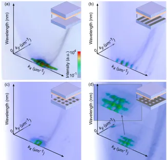
Figure 3 Dispersion tomography of lasing in (a) an unpatterned cavity, (b) a stripe-grating cavity at p=7µm, (c) a dot-grating at p=7µm, and (d) a hole-grating atp=8µm (compare with sketches as inset). The characteristics of the grating employed are manifested in the coherentk-space emission of the cor-responding microcavity as well. In turn, coherence in real space is spread ac-cording to the Fourier-transformation of the laser modes observed here i.e. uni-formly (a), mainly inx-direction (b), or in x- andy- directions ((c),(d)).
3.3. Dispersion Tomography of Phase-Locked
Lasing Modes
As a final step, stimulated emission is also assessed in the two-dimensional gratings of metal dots and holes introduced earlier. To obtain a full picture of the coherent mode, the dispersion inkx-direction is recorded while tomographically
scanning theky-direction by moving the Fourier-imaging
lens out of the optical axis [30]. Figure 3 shows the recre-ated three-dimensional tomograms of stimulrecre-ated emission comparing an unpatterned laser (a) and devices with a stripe grating at p=7 µm (b), a metal dot grating atp=7 µm (c), and a hole grating atp=8 µm (d). For the unpatterned cavity and the stripe-grating, the mode is not confined in
kydirection and thus shows a large width inkspace. Inkx
direction, however, the difference between the two becomes most striking. The mode of the unpatterned laser covers at least five of the individual spots observed in the stripe grating, suggesting an inverse behaviour in real space. In the two-dimensional gratings, thekspace dispersion behaves according to the Fourier transform of the actual grating, suggesting that emission is concentrated at the corners of metal dots for grating type (2), Fig. 3 (c), and inside the metal-free holes for the inverse grating as seen in Fig. 3 (d) (compare schematic 2-D FFT in supporting information, Fig. S3). In both cases, the observed mode fine structure points toward an increased in-plane spread of coherence in two dimensions. Even for a comparatively large aspect ratio of metal-covered to metal-free areas as in Fig. 3 (d), macro-scopically coherent emission is obtained in these organic
microcavities. This effect should allow designing effective electrodes for electrically driven solid state organic micro-lasers.
4. Conclusion
Acknowledgements
The authors gratefully acknowledge financial support by the Deutsche Forschungsgemeinschaft, Projects No. LE 747/53-1 and LE 747/55-747/53-1, and via the excellence cluster cfaed. A.M. and M.C.G. acknowledge additional funding by the Volkswagen-Stiftung, Project No. A123031. K.L. acknowl-edges support by the Canadian Institute for Advanced Re-search (CIFAR).
Supporting Information
Supporting information containing additional dispersion measurements, input-output measurements, as well as fast Fourier transformation images are available. In addition, supporting movies 1-5 show rotating animations of Fig. 1 (c) and Fig. 3 (a)-(d).
Key words: organic microlaser, Tamm plasmon polariton, phase locked lasing, metal-organic microcavity, photonic lattices
References
[1] S. Ch´enais and S. Forget, “Recent advances in solid-state
organic lasers,”Polymer International, vol. 61, no. 3, pp. 390–
406, 2012.
[2] A. J. Kuehne and M. C. Gather, “Organic lasers: recent de-velopments on materials, device geometries, and fabrication
techniques,”Chemical Reviews, vol. 116, no. 21, pp. 12823–
12864, 2016.
[3] J. Liu, H. Zhang, H. Dong, L. Meng, L. Jiang, L. Jiang, Y. Wang, J. Yu, Y. Sun, W. Hu, and A. J. Heeger, “High
mobility emissive organic semiconductor,”Nature
Communi-cations, vol. 6, p. 10032, 2015.
[4] K. Daskalakis, S. Maier, R. Murray, and S. K´ena-Cohen, “Nonlinear interactions in an organic polariton condensate,”
Nature Materials, vol. 13, no. 3, pp. 271–278, 2014. [5] J. D. Plumhof, T. St¨oferle, L. Mai, U. Scherf, and R. F.
Mahrt, “Room-temperature bose–einstein condensation of
cavity exciton–polaritons in a polymer,”Nature Materials,
vol. 13, no. 3, pp. 247–252, 2014.
[6] C. P. Dietrich, A. Steude, L. Tropf, M. Schubert, N. M. Kro-nenberg, K. Ostermann, S. H¨ofling, and M. C. Gather, “An exciton-polariton laser based on biologically produced
fluo-rescent protein,”Science Advances, vol. 2, no. 8, p. e1600666,
2016.
[7] K. J. Vahala, “Optical microcavities,” Nature, vol. 424,
no. 6950, pp. 839–846, 2003.
[8] M. Kaliteevski, I. Iorsh, S. Brand, R. Abram, J. Chamberlain, A. Kavokin, and I. Shelykh, “Tamm plasmon-polaritons: Pos-sible electromagnetic states at the interface of a metal and a
dielectric Bragg mirror,”Physical Review B, vol. 76, no. 16,
p. 165415, 2007.
[9] R. Br¨uckner, M. Sudzius, S. Hintschich, H. Fr¨ob, V. Lyssenko, and K. Leo, “Hybrid optical Tamm states in a planar dielectric
microcavity,”Physical Review B, vol. 83, no. 3, p. 033405,
2011.
[10] C. Symonds, S. Azzini, G. Lheureux, A. Piednoir, J. Benoit, A. Lemaitre, P. Senellart, and J. Bellessa, “High quality
fac-tor confined tamm modes,”Scientific Reports, vol. 7, no. 1,
p. 3859, 2017.
[11] R. Br¨uckner, V. Lyssenko, S. Hofmann, and K. Leo, “Lasing of Tamm states in highly efficient organic devices based on
small-molecule organic semiconductors,”Faraday
Discus-sions, vol. 174, pp. 183–201, 2014.
[12] C. Symonds, G. Lheureux, J. Hugonin, J. Greffet, J. Laver-dant, G. Brucoli, A. Lemaitre, P. Senellart, and J. Bellessa,
“Confined Tamm plasmon lasers,”Nano Letters, vol. 13, no. 7,
pp. 3179–3184, 2013.
[13] Z.-Y. Yang, S. Ishii, T. Yokoyama, T. D. Dao, M.-G. Sun, P. S. Pankin, I. V. Timofeev, T. Nagao, and K.-P. Chen, “Nar-rowband wavelength selective thermal emitters by confined
tamm plasmon polaritons,”ACS Photonics, vol. 4, no. 9,
pp. 2212–2219, 2017.
[14] M. Wurdack, N. Lundt, M. Klaas, V. Baumann, A. V. Ka-vokin, S. H¨ofling, and C. Schneider, “Observation of hybrid Tamm-plasmon exciton-polaritons with GaAs quantum wells
and a MoSe 2 monolayer,”Nature Communications, vol. 8,
no. 1, p. 259, 2017.
[15] C. Grossmann, C. Coulson, G. Christmann, I. Farrer, H. Beere, D. Ritchie, and J. Baumberg, “Tuneable polariton-ics at room temperature with strongly coupled tamm plasmon
polaritons in metal/air-gap microcavities,”Applied Physics
Letters, vol. 98, no. 23, p. 231105, 2011.
[16] C. Zhang, K. Wu, V. Giannini, and X. Li, “Planar hot-electron
photodetection with tamm plasmons,”ACS Nano, vol. 11,
no. 2, pp. 1719–1727, 2017.
[17] A. Mischok, B. Siegmund, D. S. Ghosh, J. Benduhn, D. Spoltore, M. Bohm, H. Frob, C. Korner, K. Leo, and K. Vandewal, “Controlling tamm plasmons for organic
narrowband near-infrared photodetectors,”ACS Photonics,
vol. 4, no. 9, pp. 2228–2234, 2017.
[18] A. Mischok, V. G. Lyssenko, R. Br¨uckner, F. L¨ochner,
R. Scholz, A. A. Zakhidov, H. Fr¨ob, and K. Leo, “Zero-andπ
-states in a periodic array of deep photonic wires,”Advanced
Optical Materials, vol. 2, no. 8, pp. 746–750, 2014. [19] O. Gazzano, S. M. de Vasconcellos, K. Gauthron,
C. Symonds, J. Bloch, P. Voisin, J. Bellessa, A. Lemaˆıtre, and P. Senellart, “Evidence for confined tamm plasmon modes un-der metallic microdisks and application to the control of
spon-taneous optical emission,”Physical Review Letters, vol. 107,
no. 24, p. 247402, 2011.
[20] I. Y. Chestnov, E. Sedov, S. Kutrovskaya, A. Kucherik, S. Arakelian, and A. Kavokin, “One-dimensional tamm plas-mons: Spatial confinement, propagation, and polarization
properties,”Physical Review B, vol. 96, no. 24, p. 245309,
2017.
[21] A. Mischok, R. Br¨uckner, M. Sudzius, C. Reinhardt, V. G. Lyssenko, H. Fr¨ob, and K. Leo, “Photonic confinement in
laterally structured metal-organic microcavities,”Applied
Physics Letters, vol. 105, no. 5, p. 051108, 2014.
[22] R. Br¨uckner, A. A. Zakhidov, R. Scholz, M. Sudzius, S. Hintschich, H. Fr¨ob, V. Lyssenko, and K. Leo, “Phase-locked coherent modes in a patterned metal-organic
micro-cavity,”Nature Photonics, vol. 6, no. 5, pp. 322–326, 2012.
[23] H. Ohadi, R. Gregory, T. Freegarde, Y. Rubo, A. Kavokin, N. G. Berloff, and P. Lagoudakis, “Nontrivial phase coupling
in polariton multiplets,”Physical Review X, vol. 6, no. 3,
[24] E. Tan, H. Sigurdsson, and T. Liew, “Parity bifurcations in trapped multistable phase locked exciton-polariton
conden-sates,”arXiv preprint arXiv:1712.02559, 2017.
[25] A. J. Koll´ar, A. T. Papageorge, V. D. Vaidya, Y. Guo, J. Keel-ing, and B. L. Lev, “Supermode-density-wave-polariton con-densation with a bose–einstein condensate in a multimode
cavity,”Nature Communications, vol. 8, 2017.
[26] G. Christmann, G. Tosi, N. G. Berloff, P. Tsotsis, P. S. El-dridge, Z. Hatzopoulos, P. G. Savvidis, and J. J. Baumberg, “Oscillatory solitons and time-resolved phase locking of two
polariton condensates,” New Journal of Physics, vol. 16,
no. 10, p. 103039, 2014.
[27] T. Gao, E. Estrecho, G. Li, O. Egorov, X. Ma, K. Winkler, M. Kamp, C. Schneider, S. Hoefling, A. Truscott, and E. A.
Ostrovskaya, “Talbot effect for exciton polaritons,”Physical
Review Letters, vol. 117, no. 9, p. 097403, 2016.
[28] A. Nalitov, T. C. H. Liew, A. Kavokin, B. Altshuler, and Y. Rubo, “Spontaneous polariton currents in periodic lateral
chains,”Physical review letters, vol. 119, no. 6, p. 067406,
2017.
[29] K. Winkler, J. Fischer, A. Schade, M. Amthor, R. Dall, J. Geßler, M. Emmerling, E. A. Ostrovskaya, M. Kamp, C. Schneider, and S. H¨ofling, “A polariton condensate in a
photonic crystal potential landscape,”New Journal of Physics,
vol. 17, no. 2, p. 023001, 2015.
[30] A. Mischok, F. Lemke, C. Reinhardt, R. Br¨uckner, A. Za-khidov, S. Hintschich, H. Fr¨ob, V. Lyssenko, and K. Leo, “Dispersion tomography of an organic photonic-wire
micro-cavity,”Applied Physics Letters, vol. 103, no. 18, p. 183302,
2013.
[31] P. Ramachandran and G. Varoquaux, “Mayavi: 3d
visualiza-tion of scientific data,”Computing in Science & Engineering,
vol. 13, no. 2, pp. 40–51, 2011.
[32] F. J. L¨ochner, A. Mischok, R. Br¨uckner, V. G. Lyssenko, A. A. Zakhidov, H. Fr¨ob, and K. Leo, “Coexisting localized and extended optical Bloch states in a periodic deep wire
ar-ray microcavity,”Superlattices and Microstructures, vol. 85,
pp. 646–652, 2015.
[33] G. Panzarini, L. C. Andreani, A. Armitage, D. Baxter, M. Skolnick, V. Astratov, J. Roberts, A. V. Kavokin, M. R. Vladimirova, and M. Kaliteevski, “Exciton-light coupling in single and coupled semiconductor microcavities:
Polari-ton dispersion and polarization splitting,”Physical Review B,
vol. 59, no. 7, p. 5082, 1999.
[34] T. Gutbrod, M. Bayer, A. Forchel, P. A. Knipp, T. L. Reinecke, A. Tartakovskii, V. D. Kulakovskii, N. A. Gippius, and S. G. Tikhodeev, “Angle dependence of the spontaneous emission
from confined optical modes in photonic dots,” Physical
Review B, vol. 59, pp. 2223–2229, Jan 1999.
[35] C. W. Lai, N. Y. Kim, S. Utsunomiya, G. Roumpos, H. Deng, M. D. Fraser, T. Byrnes, P. Recher, N. Kumada, T.
Fuji-sawa, and Y. Yamamoto, “Coherent zero-state andπ-state
in an exciton-polariton condensate array,”Nature, vol. 450,
no. 7169, 2007.
[36] A. Mischok, T. Wagner, R. Br¨uckner, M. Sudzius, H. Fr¨ob, V. G. Lyssenko, and K. Leo, “Lasing and macroscopic coher-ence of hybridized modes in coupled 2d waveguide-vcsel
res-onators,”Advanced Optical Materials, vol. 4, no. 8, pp. 1215–