Abstract— in this study, the problem of natural convection and radiation heat transfer in a micro fin array heat sink is numerically investigated. A two-dimensional model is used to formulate the problem. The governing equations of the problem are mass, momentum and energy equations of the fluid along with conduction equation in the micro fin. The radiation exchange between two adjacent fins, between fin and base plate and between fin and ambition is considered. To address the micro dimensional effects of the problem Maxwell's velocity slip and Smoluchowski's temperature jump boundary conditions are used. A finite difference approach is used to solve transient vorticity-stream function formulation using the alternating direction implicit (ADI) scheme .The steady state velocity and temperature field which are obtained by marching through the transient stage, are used to calculate the local Nusselt number and total heat transfer. The effects of the fin height on the heat transfer are investigated through parametric studies.
Index Terms— Free convection, MEMS, Micro fin array heat sink, Radiation, Slip flow.
I. INTRODUCTION
In the past decades, rapid growth in micro-electro-mechanical systems (MEMS) has urged the need for more compact and smaller devices. These devices produce a relatively high amount of heat but don’t have enough surface area in order to dissipate this heat. Also, the temperature of electronic devices is a major factor in their durability and function. All these factors highlight the urgent necessity of efficient cooling systems for these devices.
Micro fin array heat sinks seem to be an efficient cooling system for small electronic devices. These heat sinks are reliable and noiseless cooling systems that don’t need a lot of power to run. A typical micro fin array heat sink is made of several rectangular fins with micro dimensions that are mounted on a flat plate.
To obtain an efficient design for micro fin array heat sinks, the free convection heat transfer in the fluid field that surrounds all the fins should be studied. Also, a portion of total heat transfer is carried out by radiation exchange
Manuscript received October 21, 2009.
Hossein Shokouhmand is a distinguished Professor of the department of Mechanical Engineering at University Of Tehran, Iran.(email: [email protected])
Ali Ahmadpour is a graduate student of the department of Mechanical Engineering at University Of Tehran, Iran. (email: [email protected])
between adjacent fins, fin and base plate and fin and ambient that should be investigated thoroughly.
Although the heat transfer from fin arrays through natural convection is a three-dimensional phenomenon, a two-dimensional model is assumed here because the length of heat sink is much larger than its other dimensions. The micro-dimensional effect of the problem is modeled by using slip velocity and temperature boundary jump conditions near solid walls.
The concept of micro dimensional heat sinks was first introduced by Tuckerman and Pease [1] who conducted some experiments on silicon based micro channel heat sinks cooled with water. Wei et al. [2] studied pool boiling on the micro pin-finned surface in FC-72.Go et al.[3] fabricated a micro fin array by bulk Si micromachining and studied its performance under periodic pressure distribution. J.S.Kim and B.K.Park and J.S.Lee [4] experimentally investigated the performance of micro fin arrays with fin height of 100 and 200µm. It turns out that heat transfer correlation for macrofin arrays is improper in estimating heat transfer from micro fin arrays. Also, the orientation effect is negligible at micro scales.
Numerical investigations of micro fin array heat sinks are rare to find. Hence, to study this type of heat sinks, the conservation of mass, momentum and energy balance equation of the flow are solved simultaneously with the heat conduction and radiation equation within two adjacent fins enclosure. The radiation heat transfer occurs between the surfaces of two adjacent fins, the fin and the base surface and the fin and the wall of the room. The steady state temperature and the velocity field in the fluid are obtained from the solution of the two-dimensional transient stream function-vorticity equations, using the alternating direction
implicit (ADI) scheme and marched through the transient
stage.
II. PHYSICAL MODEL AND FORMULATION
The array consists of many uniformly spaced fins which are mounted on a horizontal isothermal flat base plate with temperature Tb as depicted in Fig. 1.
A. Fluid governing equations
Heat is transferred from the fin surface to the surrounding fluid by laminar natural convection. The governing equations are continuity, momentum and energy equation. In
Heat Transfer from a Micro Fin Array Heat Sink
by Natural Convection and Radiation under Slip
Flow Regime
momentum equation Boussinesq approximation is considered. Using the following dimensionless variables,
H V VH
H
t
2 ) 1 ( T T T T b
The governing equation for fluid are given as,
(2)Pr 1 . . ) . ( 0 . 2 2 V e Gr V P V V V V x
Where Grashof number Gr, and Prandtl number Pr are
defined as,
T T
Pr (3)H g
Gr 2b
3
In our two- dimensional model, we use vorticity-stream function formulation to achieve a more convenient set of governing equations. For a two dimensional flow dimensionless vorticity Ω is defined as,
) 4 ( 2
1
V
For a two-dimensional, incompressible flow dimensionless stream function is defined as,
) 5 ( X V Y U According to definitions of vorticity and stream function, there is a relation between these quantities as,
) 6 ( 2
Eq.(6) is called stream function equation. Using the definition of vorticity, one can combine X- and Y- momentum equations into a single equation which is called vorticity transport equation. Thus, the new set of governing equations in terms of vorticity and stream function can be written as, Y Gr Y X Y V X U
( 2 )
2 2 2 2 2 2 2 Y X ) 7 ( ) ( Pr 1 2 2 2 2 Y X Y V X U
B. Fin equation
In our study the fin thickness (tf) is negligible so that a one
dimensional temperature distribution is assumed along the fin. The heat is conducted through fin height and then transmitted to surroundings by natural convection and radiation from fin surface. The fin equation is given as,
) 8 ( Pr , 0 2 2 d d q N Y M X W r W rad R Y
W
Where
) 9 ( ) ( 2 2 4 4 2 T q q T T T T k k Lt t L H M t T T k T H N rad rad b W W W r W f f f b W R and
q
rad,W is radiation heat flux from fin surface.Radiation analysis using infinitesimal areas [5] is used to predict the radiation heat transfer from fin surface and base plate. In this study we assume that all surfaces are diffuse gray and we consider the open top boundary of the geometry as a black surface with ambient temperature. Also, we assume that all the properties of surfaces are independent of temperature.
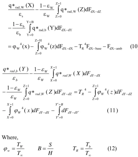
The radiative heat flux from fin surface regarding to radiation exchange with adjacent fin, base plate and environment, can be formulated by using non-dimensional variables as, ) 10 ( F F T dF ) z ( ) x ( dF ) Y ( q 1 dF ) Z ( q 1 ) X ( q amb dX base dX 4 R H Z 0 Z dX dX 4 W 4 W B Y 0 Y dY dX b , rad b b 1 Z 0 Z dZ dX W , rad W W s W , rad
) 11 ( ) ( ) ( ) ( 1 ) ( 1 ) ( 1 0 0 4 1 0 4 4 1 0 , 1 0 , ,
X X B Y Y Y d dY dX dY W Z Z dZ dY W R Z Z dZ dY W rad W W X X dX dY W rad W W b b rad dF dF x dF z T dF Z q dF X q Y q Where, ) 12 ( T T T H S B T T b R W w In Eqs. (10) & (11), dF is configuration factor between differential surface elements that are available in literature [5].
C. Boundary conditions
In this paper, the rarefaction effect is modeled through Maxwell’s velocity slip and Smoluchowski’s temperature jump boundary conditions [6, 7].
H
L
[image:2.595.302.545.416.692.2]S
) 13 ( 2
s m
m w
s
n u F
F u
u
) 14 ( Pr
1 1 2 2
s T
T w
s
n T F
F T
T
m
F and FT are the momentum and energy
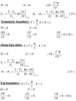
accommodation coefficient respectively. For gases these coefficients are approximately 1.0. Along the fin surface and base plate tangential velocity and temperature are modified through Eqs. (13) & (14). Due to the geometrical symmetry, it is sufficient to analyze only half of the fin spacing. as shown in Fig. 3.The boundary conditions at right, left, bottom and top boundaries of the enclosure are given below,
Along fin height:Y 0,0 X 1
) 15 ( Pr
2 ,
2
, 0
, 0
0 0
2 2
Y T
T w
j Y m
m s
Y Kn F
F Y
U Kn F
F U
Y V
Symmetric boundary: ,0 1
2
B X Y
) 16 ( 0 , 0
, 0
0 , 0
Y Y
U Y
V
Along base plate: , 0
2 0Y B X
0
2 2
2
, 0
, 0
X m
m s
X V Kn F
F V
X U
) 17 ( Pr
2
0
X T
T w
j
X Kn F
F
Top boundary: , 1
2 0Y B X
) 18 ( 0 , 0
, 0
0 , 0
X X
U X
V
III. NUMERICAL SOLUTION
In order to obtain a proper numerical solution for Eqs. (7-18) finite differences method is utilized. Vorticity transport and energy equation are discretized by the
alternating direction implicit (ADI) scheme and a successive
over relaxation method (SOR) is used to solve stream function equation. Convection terms in governing equation are approximated by first order upwind scheme. A fully implicit method is used for fin equation and the convection and radiation heat fluxes are computed by the temperature of the fin from previous time step through trapezoidal numerical integration.
The solution procedure can be summarized as,
1. Begin from initial conditions for velocities (zero everywhere) and temperature (zero everywhere except base plate)
2. Solve fin equation to obtain temperature distribution along the fin which is the boundary condition for fluid energy equation.
3. Solve vorticity transport and energy equation to acquire vorticity and temperature values everywhere.
4. Solve stream function equation to obtain velocities throughout the domain.
5. Repeat the above procedure until the steady state solution is obtained.
In this paper, for all the cases we use a 50×40 uniform grid size corresponding to x-and y-direction respectively. For the SOR method we use following convergence criterion,
, max 10 7 (19), 1
,
k n
j i
k n
j i k n
j i
IV. RESULT AND DISCUSSION
Validation of current numerical solution is investigated by a comparison of numerical result and experimental data available in literature. Experimental data by J.S.Kim and B.K.Park and J.S.Lee [4] is illustrated and compared with numerical results in Fig. 4. In Fig. 4 the variation of average Nusselt number with Rayleigh number based on fin spacing is shown. There is a good agreement between numerical and experimental data and the average relative difference between two results is 6.9%.
[image:3.595.307.529.61.242.2]Rayleigh number based on fin spacing is defined by,
[image:3.595.46.297.449.782.2]
(20)3
g S T T
Ra b
s
The average convective heat transfer coefficient (hc) is
defined by following equations:
) 21 ( )
( ,
T T A
Q h
b T conv c
Where A is total heat transfer area including fin surface and
Q
conv,Tis total convective heat transfer from heat sink. Average Nusselt number based on fin spacing is defined by,) 22 (
k S h
Nu c
s
The result presented here are for a fin with thickness (tf) of
40 µm and the length of fin array (L) is 10mm. All the surfaces are assumed to be gray and diffuse with emissivity of 0.7 and the thermal conductivity is 156W/m2K. Fluid
properties are evaluated at film temperature Tf which is
defined as below,
) 23 ( 2
T T
T b
f
Where Tb is base plate temperature and the ambient
temperature is 20C. The thermal expansion coefficient (β) is calculated as 1/T∞.
Ras
Nu
s
0.01 0.02 0.01
0.015 0.02 0.025 0.03 0.035 0.04 0.045
Exprimental Results of Kim et al.[9] Numerical Results
[image:4.595.313.503.242.633.2]Fig. 4 Comparison of numerical results with experimental data of
Kim et al. [9]
A. Case Study
[image:4.595.314.505.245.421.2]In this section we are going to investigate the case of a fin a rray heat sink with geometrical and thermal conditions that are shown in Table. 1.
Table. 1 Specifications of the problem
Fin height 200µm
Fin spacing 160 µm
Base plate temperature 80C
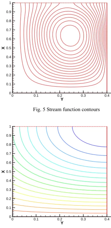
In Fig. 5 stream function contours are drawn across the two-fin enclosure. An “up and down” flow pattern is observed. Cold air enters from the middle of enclosure while hot air rises near the fin. Also, isothermal lines are shown in Fig. 6 where the maximum temperature occurs at the fin surface and the temperature decreases monotonically by
moving toward the middle of fin spacing.
Vertical velocity profiles in various distances from the fin are depicted in Fig. 7. In vicinity of the fin, because of natural convection flow the vertical velocity is positive and close to the middle of enclosure the sign of vertical velocity changes due to down ward flow of cold air. The values of the vertical velocity peaks along the line y=s/2.
Variation of horizontal velocity is shown in Fig. 8. The horizontal velocity is zero on the fin surface and along symmetry line and between these two locations it takes first negative and then positive values which are the sign of a counter clockwise circulation within the enclosure. This circulation takes the cold air from the middle of enclosure to the fin.
Y
X
0 0.1 0.2 0.3 0.4 0
0.1 0.2 0.3 0.4 0.5 0.6 0.7 0.8 0.9 1
Fig. 5 Stream function contours
Y
X
0 0.1 0.2 0.3 0.4 0
0.1 0.2 0.3 0.4 0.5 0.6 0.7 0.8 0.9 1
Fig. 6 Temperature contours
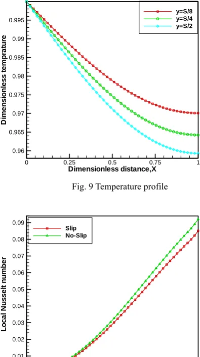
Temperature profiles along vertical lines within the enclosure are shown in Fig. 9. The maximum temperature occurs on base plate and it reduces from base plate to top boundary. Also, the temperature of fluid close to fin surface is higher than the middle of enclosure due to natural convection heat transfer from the fin to surrounding fluid.
[image:4.595.59.261.355.541.2]peaks at fin tip. Using slip velocity and temperature jump boundary conditions decrease temperature gradient and local Nusselt number due to sharp jump in temperature near the fin. There is a remarkable difference between results that are obtained from slip flow consideration and those obtained from conventional no-slip flow. For example for this case the total convection heat transfer rate that acquired from slip flow is 2.4668mW when the total convection heat transfer that is obtained from continuum assumptions is 2.6411mW. The relative difference between these two values is 7% which cannot be neglected. This fact highlights the importance of micro dimensional effects in this problem that should be addressed properly
Dimensionless distance,X
D
im
en
s
io
n
les
s
v
el
o
c
it
y
,U
0 0.25 0.5 0.75 1 -6E-06
-5E-06 -4E-06 -3E-06 -2E-06 -1E-06 0 1E-06 2E-06
[image:5.595.308.507.71.244.2]y=S/8 y=S/4 y=3S/8 y=S/2
Fig. 7 Vertical velocity profile
Dimensionless distance,X
D
ime
ns
ionl
e
s
s
v
e
lo
c
it
y
,V
0 0.25 0.5 0.75 1 -1E-06
-8E-07 -6E-07 -4E-07 -2E-07 0 2E-07 4E-07 6E-07 8E-07
[image:5.595.308.506.73.426.2]y=S/8 y=3S/8 y=S/2
Fig. 8 Horizontal velocity profile
Variation of radiation heat flux along the fin is depicted in Fig. 11. The radiation heat transfer peaks at the top of the fin where it has minimum configuration factor from base plate and it receives less radiation from it. As fin spacing rises, there is more available surface for radiation exchange which is the reason for increase in values of radiation heat flux.
In Fig. 12 variation of dimensionless radiation heat flux along base plate is presented. The maximum heat flux occurs at the beginning of the plate due to minimum configuration factor form fin surface and in the middle of the plate heat flux is approximately constant.
Dimensionless distance,X
D
ime
ns
ionl
e
s
s
te
m
pr
a
tur
e
0 0.25 0.5 0.75 1 0.96
0.965 0.97 0.975 0.98 0.985 0.99 0.995
y=S/8 y=S/4 y=S/2
Fig. 9 Temperature profile
Dimensionless distance,X
Lo
c
a
l
N
us
s
e
lt
numbe
r
0 0.25 0.5 0.75 1 0
0.01 0.02 0.03 0.04 0.05 0.06 0.07 0.08 0.09
Slip No-Slip
Fig. 10 Local Nusselt number along fin for slip and no-slip conditions
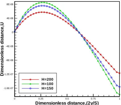
B. Effect of fin height
In order to study the effect of fin height on heat transfer from micro fin array heat sinks, we investigate the case of a fin array heat sink with fin spacing of 60µm and the base temperature of 100C. The fin height is set to be 100,150 and 200µm.
In Fig. 13, vertical velocity along mid height of the fin for different fin heights is drawn. The value of vertical velocity reduces by increase in fin height due to lower temperature gradient within two-fin enclosure for bigger fin heights. Since the variation of fin height affects down and up flow equally, transition from up to down flow occurs remains unaffected.
Variation of temperature along line y=S/4 for different fin height is depicted in Fig. 14. For higher fin heights there is more space for the fluid to circulate and this leads to more intense heat transfer and fluid flow and lower temperature.
[image:5.595.48.249.233.404.2] [image:5.595.47.248.407.612.2]should be included in study of natural convection micro-fin heat sinks.
Dimensionless distance,X
D
im
e
ns
ionl
e
s
s
R
a
di
a
ti
on
he
a
t
fl
u
x
0.25 0.5 0.75 1 0.15
0.2 0.25 0.3 0.35 0.4
Fig. 11 Dimensionless radiation heat flux along fin height
Dimensionless distance,Y
D
ime
ns
ionl
e
s
s
ra
d
ia
ti
on
h
e
a
t
fl
ux
0 0.1 0.2 0.3 0.4 0.4
[image:6.595.64.261.96.270.2]0.5 0.6 0.7 0.8 0.9
Fig. 12 Dimensionless radiation heat flux along base plate
Dimensionless distance,(2y/S)
D
im
e
ns
ionl
e
s
s
d
is
ta
nc
e
,U
0 0.25 0.5 0.75 1
-1.6E-07 -1.2E-07 -8E-08 -4E-08 0 4E-08 8E-08
[image:6.595.56.251.307.483.2]H=200 H=100 H=150
Fig. 13 Dimensionless vertical velocity along x=H/2
Table. 2 Heat transfer from micro fin arrays with different heights
Dimensionless distance,X
D
ime
ns
ionl
e
s
s
te
m
pr
a
tur
e
0 0.25 0.5 0.75 1 0.96
0.965 0.97 0.975 0.98 0.985 0.99
0.995 H=200H=100
H=150
Fig. 14 Dimensionless temperature along y=S/4
V. CONCLUSION
A numerical investigation was conducted on natural convection and radiation heat transfer from micro fin array heat sinks. Micro-dimensional effects were considered by using slip velocity and temperature jump boundary conditions on solid surfaces. It was shown that micro-dimensional effects are too important to be neglected. In all the cases, an “up and down” flow pattern was observed. Also, the effect of fin height was studied. It is observed that radiation contributes up to 22% of the total heat dissipation which is a significant effect that shouldn’t be excluded from the performance study of micro fin arrays.
REFERENCES
[1] D. B. Tuckerman, R. F.W. Pease, “High-performance heat sinking for VLSI”, IEEE Electro. Dev. Lett. EDL-2 ,vol.5, 1981,pp.126–129 [2] J. J.Wei,H. Honda,”Effects of fin geometry on boiling heat transfer
from silicon chips with micro-pin-fins immersed in FC-72”,Int.J.Heat Mass Transfer,vol.46,2003,pp.4059-4070.
[3] Z. Y. Guo, Z. X. Li,”Size effect on single-phase channel flow and heat transfer at microscale”,Int.J.Heat Fluid Flow vol.24,2003,pp.284-298 [4] J. S. kim, B. K. Park, J. S. Lee, “Natural convection heat transfer
around micro fin arrays”, Experimental Heat Transfer vol.21, 2008,pp.55-12
[5] R. Siegle, J. R. Howell, Thermal radiation heat transfer, 4th ed., New
York: TAYLOR e FRANCIS, 2002,ch 1-6.
[6] S. Kakac, L. L. Vasiliev, Y. Bayazitoglu, Y. Yener, Microscale heat transfer, Fundamentals and applications, NATO Science series,
Springer, 2004
[7] Z .M .Zhang. Nano/microscale heat transfer, McGraw Hill, 2007
Fin height 100 µm 150 µm 200 µm
Convection heat transfer (mW)
1.3616 1.3275 1.4547 Radiation
heat transfer
(mW) 0.3749 0.3856 0.3932
Total
heat transfer (mW)
1.7365 1.7131 1.8479 Radiation
[image:6.595.61.257.532.703.2]