Design and Implementation of Active Filter for Data
Acquisition System
Ms.Mya Thandar Kyu , Dr.Zaw Min Aung and Dr.Zaw Min Naing
Abstract -A filter is a device that passes electric signals at certain frequency or frequency ranges while preventing the passage of others. This paper focuses on active low-pass Butterworth filters design. In communication, data acquisition system usually requires anti-aliasing low-pass filter as well as low-pass noise filter in their preceding signal condition stages. In this paper design of fourth-order low-pass filters is the main topic of consideration. This paper will examine how to implement Butterworth filter and design methods. And this paper describes mathematics calculations and implementation of Butterworth filter with MATLAB and Circuit Maker.
Key words: low-pass filter, implementation, active filter, Butterworth
I. INTRODUCTION
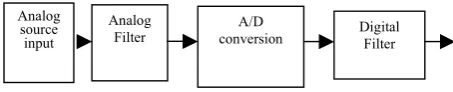
[image:1.595.52.279.526.572.2]Analog filters are continues-time filters that can be implemented with resistors, capacitors, amplifiers or specialized elements, etc. as passive and active filters, which have been used for along time in electrical engineering. Analog filters can be found in almost every electronic circuit. Audio systems use them for preamplification, equalization, and tone control. In communication systems, filters are used for tuning in specific frequencies and eliminating others. Digital signal processing systems use filters to prevent the aliasing of out-of-band noise and interference. The data acquisition system signal chain that includes an analog filter is shown in Fig.1.
Fig .1. The data acquisition system signal chain can utilize analog or digital filtering techniques or combination of both.
Manuscript received December 10, 2008.This work was supported in part by the Ministry of Science and Technology, Union of Myanmar.
Ms. Mya Thandar Kyu is with the Mandalay Technological University, Mandalay, Myanmar. Contact Phone: 095-2-88704(Electronic Engineering Department), Fax: 095-2-88702(office, MTU), e-mail: [email protected] and [email protected]. Dr. Zaw Min Aung and Dr.Zaw Min Naing are her supervisors and they are rector of Mandalay Technological University, Myanmar and pro-rector of Hlaing Tharyar Technological University , Myanmar
A system that includes an analog filter, a digital filter or both is shown in Figure 1.When an analog filter is implemented, it is done prior to the analog-to-digital conversion. In contrast, when a digital filter is implemented, it is done after the conversion from analog-to-digital has occurred. Analog filtering can remove noise superimposed on the analog signal before it reaches the Analog-to-Digital Converter. In these types of systems, an analog filter can reduce noise in the out-of-band frequency region. In the data acquisition system, the analog signal will go directly into an active low pass filter. In this system, the bandwidth of interest of the analog signal is DC to 1 kHz. The low pass filter will be designed so that high frequency signals from the analog input do not pass through to the A/D Converter in an attempt to eliminate aliasing errors. The implementation analog signal will go directly into an active low pass filter. The implementation and order of this filter will be modified according to the design parameters. Excluding the filtering function, the anti-aliasing filter will not modify the signal further that is implement a gain or invert the signal. The low pass filter segment will be followed by a 12-bit A/D Converter. The sampling rate of the A/D Converter will be 20 kHz, making 1/2 of Nyquist equal to 10 kHz. The ideal signal-to-noise ratio of a 12-bit A/D Converter of 74dB. This design parameter will be used when determining the order of the anti-aliasing filter. In the second the section of this application, the anti-aliasing filter design and implementation will be performed. In this section anti-aliasing filter requirements will be determined. Filter characteristics and architecture will also be discussed in this section. Moreover, filter design consideration over Butterworth filter, Chebyshev type I filter and Bessel filter will be performed. Then, implementation with 4th
Butterworth low pass filter design will be carried out in order to prevent the aliasing parameter. The third and final part of this application, the comparison of the Circuit Maker simulation and calculated result will be discussed.
II. ANTI-ALIASING FILTER
These three design parameters will be used to implement
appropriate anti-aliasing filters:
1. Cut-off frequency for filter must be 1 kHz or higher. 2. Filter attenuates the signal to -74dB at 10 kHz. 3. Flat frequency response in the pass-band.
Analysis of Butterworth, Chebyshev type I and Bessel filter types, then should be done to decide which type is most suitable for implementation, depending on the system requirements.
Analog source input
Analog
Pass Band
Stop Band
fcut-off fstop Apass Band
Frequency(Hz) Amax
P ripple
S ripple
[image:2.595.315.519.116.236.2]Astop
Fig.2.Analog low pass filter design parameters requirements In Fig.2. Apass is the 3 dB limit, Astop is the attenuation
requirement in the stop band, fcut-off is the frequency end of
pass band, set to 1kHz, fstop is the frequency at the beginning
of stop band, the zone between fpass and fstop is the transition
zone, Pripple is the passband ripple , Sripple is the stopband
ripple and defined as the difference between the gain in the pass band region and the gain that is achieved in the stop band region is A MAX = APASS - ASTOP.
III. FILTER CHARACTERISTIC AND ARCHITECTURE If an ideal low-pass filter existed, it would eliminate signals above the cutoff frequency, and perfectly pass signals below the cutoff frequency. In real filters, various trade-offs are made to get optimum performance for a given application.
Butterworth filters are termed
maximally-flat-magnitude-response filters, optimized for gain flatness in the pass-band and the attenuation is –3 dB at the cutoff frequency. Above the cutoff frequency the attenuation is –20 dB/decade/order. The transient response of a Butterworth filter to a pulse input shows moderate overshoot and ringing.
Bessel filters are optimized for maximally-flat time delay
(or constant-group delay). This means that they have linear phase response and excellent transient response to a pulse input. This comes at the expense of flatness in the pass-band and rate of rolloff. The cutoff frequency is defined as the 3-dB point.
Chebyshev filters are designed to have ripple in the
pass-band, but steeper rolloff after the cutoff frequency. Cutoff frequency is defined as the frequency at which the response falls below the ripple band. For a given filter order, a steeper cutoff can be achieved by allowing more pass-band ripple. The transient response of a Chebyshev filter to a pulse input shows more overshoot and ringing than a Butterworth filter.
input
output opamp
R2 R1
C1
Fig.3.General architecture for Sallen-Key of a two-pole filter section
The architecture that has been used to implement the low-pass filter is called Sallen-Key. This was chosen because of its simplicity compared to other know architectures as multiple feedback and state variable, where the latter is for precision performance. A circuit diagram for Sallen-Key is shown in Fig.3. Sallen-Key architecture use to non-inverting port as input which normally is set for unity gain operation. This gives a very accurate unity gain filter in the pass-band. Pole-pair Q-value below there is specific good for Sallen-Key and only need one Op-amp to build a two-pole filter section.
IV. FILTER DESIGN CONSIDERATION
The three filter types Butterworth, Chebyshev type I and Bessel that were described theoretically in the previous section, are going to be simulated in Math-lab in this section. The magnitude and phase function of each filter type are going to be presented in following subsection, will the requirement written in section (I). The result of following analysis decides which filter type that is going to be implemented.
A. Butterworth filter
Butterworth filter with its flat image in the pass-band and low steepness after the cutoff frequency of 1 kHz, requires being a 4th order, to fulfill the attenuation
requirement of -74dB at 10 kHz see Fig.4. for filter response.
B. Chebyshevtype I filter
Chebyshev type I filter with ripple of 1dB in the pass-band and with steeper fall off rate after the cutoff frequency than Butterworth. It requires only being a 3rd order, to be
able to follow attenuation of -74dB at 10 kHz see Fig.5. for the filter response.
C. Bessel filter
Bessel filter, 5th order filter is needed to fulfill requirement
[image:2.595.58.268.119.258.2]Fig.4. (a) simulated responses of 4th order Butterworth
low-pass filter frequency response in dB
Fig.5. (a) simulated responses of 3rd order Chebyshev type I
low-pass filter frequency response in dB
Fig.6. (a) simulated responses of 5th order Bessel low-pass
filter frequency response in dB
Fig.4. (b) Simulated responses of 4th order Butterworth
low-pass filter phase response in degree
Fig.5. (b) simulated responses of 3rd order Chebyshev type I
low-pass filter phase response in degree
Fig.6. (b) simulated responses of 5th order Bessel low-pass
have different characteristics and thereby give different filter orders, Butterworth 4th order, Chebyshev type I 3rd
order, and Bessel 5th order. All three filters met requirements on attenuation in the stop band, but not on flat magnitude response requirements. The Bessel filter and Chebyshev type I look suitable but Butterworth met the requirement flat magnitude response best and is thereby decided to be implemented.
V. IMPLEMENTATION BUTTERWORTH LOW-PASS
FILTER DESIGN
A low-pass Butterworth filter of 4th order using
Sallen-key architecture is going to be used. When implementing a filter, the resistors and capacitors part of the Sallen-Key architecture must be calculated at first. Start the form writing out of the four poles below.
p p
i
ω
σ
±
(1)By using the buttap function of Matlab, the poles can be given as;
[z, p, k] = buttap (4); P -0.9329 + 0.3827i -0.9329 - 0. 3827i -0.3827 + 0.9329i -0.3827 - 0.9328i
Thus, Equation(1) can be rewritten as Stage (1). -0.9329
±
0.3827i and Stage (2). -0.3827±
0.9329i respectively. The quadratic function is
N(s) = (s+σp-ωp). (s+σp+ωp) = s2+2sσp+ σp2+ ωp2 (2)
Then, gives following quadratic functions on the four poles; for stage (1) s2+ 1.8478s+ 1, for stage (2) s2+ 0.7654s+ 1.
Quality values, Q are calculated according to Equation (3), for complex-pole pairs.
Re
2
Im
Re
2+
2=
Q
(3) Where Re is the real part of the complex-pole pair, and Im is the imaginary part. The respective quality values of the complex-pole pairs and the single pole is 1.847 for stage (1) and 0.7654 for stage (2).Next, a relationship between the resistors and capacitors need to the derived, which called m and n. The quality value Q can be written as
1
+
m
Q2 (m+1)2 = mn then, m+2
+
m
1
= 2Q
n
(5)
Let ( 2
Q
n
-2) = x (6)
and now Equation( 4) can be written as
m2-xm+1 = 0
(7)
The constant n, which is the relationship between the two capacitors in the pole pair cases. It should be chosen with respect to values of the capacitors as exits to buy and also keep the resistors values to a few thousand ohms. That is why one of the roots in Equation (7) is thrown away. The value Q influence the value n, the higher Q the higher n should be used. For the stage (1). Choose n = 3.3 and Q=0.54 calculate x according to Equation (6) which give x ≈ 9.32.
The solution to Equation (7) is m1 = 9.2 and m2 = 0.11,
where m1 is thrown away.
Choose a value of the capacitor C1 = 10nF and C2 =C1.n
=33nF.For Sallen-Key architecture, fpass is set to 1 kHz and
the frequency scaling factor denoted FSF, is calculated as
FSF =
Re
2+
Im
2 (8)Where Re real part of the complex-pole pair, and Im is the imaginary part. FSF ≈ 1. From this the resistor values be calculated,
mn
f
FSF
C
R
pass
.
.
.
.
2
1
1 2
π
=
(9)which give R2= 26.4 kΩ, and with the relationship
R1= R2.m= 2.91kΩ.
For the stage (2), choose n =
3
.
3
100
and Q=1.31 calculate x according to Equation (6) which give x≈9.23.
The solution to Equation (7) is m1=9.12 and m2=0.1, where
m1 is thrown away. Choose the value of the capacitor
C1=6.8nF and C2=100nF. According to the Equation (8) and
Stage(2)
Stage(1)
input
output
+ U1B TL084 33nF
6.8nF + U1A TL084
10nF
100nF
1.9k 19.3k 2.91k 26.4k
Fig.7. Schematic diagram of 4th order Butterworth
anti-aliasing filter
Fig.8. Simulated responses in Circuit Maker of 4th order
Butterworth low-pass filter; the upper plot shows the filter response in dB and the lower plot shows the phase function in degrees.
VI. DISCUSSION AND CONCLUSION
Analog filtering is a critical portion of the data acquisition system. If an analog filter is not used, signals outside half of the sampling bandwidth of the A/D converter are aliased back into the signal path. Once a signal is aliased during the digitalization process, it is impossible to differentiate between noise with frequencies in band and out of band. The main purpose of this paper is to design active low-pass filter for data acquisition system. In this work, the filter is designed as two stages. The first stage is to determine which filter is used for this application and the second stage is chosen for Butterworth low-pass filter design and implementation. The circuit is designed using TL084 amplifier since this is good for data acquisition application. The simulated response from Circuit Maker of this circuit shown in Fig.8.For this circuit implementation, a 4th order Butterworth is used with a cutoff frequency of 1
kHz. Two Sallen-Key filters are used. This filter attenuates the pass band signal -80dB at 10kHz.The simulated response is good and looks similiar with the simulated response in MATLAB. Therefore, the design filter is suitable for data acquisition application with anti-aliasing parameter.
ACKNOWLEDGMENT
The kindness and help of my supervisor Dr. Zaw Min Aung, Rector of Mandalay Technological University, Dr. Zaw Min Naing,pro-rector of Hlaing Tharyar Technological University and Dr. Yin Mon Myint, Assistance Professor Department of Electronic Engineering, Mandalay Technological University are gratefully acknowledged. Especially, I would like to express my special thank to my parents for their noble support and encouragement. REFERENCES
[1] Analog Filter Design, Volkenburg, M.E. Van, Oxford University Press.
[2] Baker, Bonnie, “Using Operational Amplifiers for Analog Gain in Embedded System Design”, AN682, Microchip Technologies, AN682, Microchip Technologies, Inc.
[3] Bonnie C.Baker,” Anti-Aliasing, Analog Filters for Data Acquisition Systems “, AN699, Microchip Technology Inc.
[4] S.Winder, Analog and Digital Filter Design 2nd ed. Woburn, MA:
Newnes 2002.
[5] Active and Passive Analog Filter Design, An Introduction, Huelsman, Lawrence p, McGraw Hill, Inc.
[6] J.Karki. (2000.Oct) Active low-pass filter design. Texas Instrument. [Online].Available: