RESEARCH ARTICLE
A REVIEW ON MICRO TURNING PROCESS
Vinayagamoorthy, R. and *Anthony Xavior, M.
School of Mechanical and Building Sciences, VIT University, Vellore-14, Tamil Nadu, India
ARTICLE INFO ABSTRACT
The paper comments on the potential for a new approach that combines the technologies to produce small machine tools for performing macro machining operations on large components. The paper also described micro fabrication systems, such as the micro-factory, and concluded that ‘many benefits will come from applying systematic approach to micro-engineering’; with the
achievement of complete process integration. In the field of manufacturing, these machines offer
more flexible solutions with the ability to work on different parts of a large structure. Some examples of these machines with applications in the aircraft, marine and power generation industries are discussed, along with some other specialist machine designs which can offer more flexible machining capabilities from the survey; a new micro turning system is realized on the basis of experience with previous prototype equipment. In this new system, a new point tool is applied to a micro turning at an elevated rotation speed. Through the measurement of cutting force under various cutting conditions, the possibility of reduction of reacting forces to a low level without deflection of the micro work was identified. The current efforts in mechanical micro-machining research and applications are surveyed and suggestions are given in the areas that should be examined and researched to the improvement of the process.
Copy Right, IJCR, 2011, Academic Journals. All rights reserved
INTRODUCTION
The paper starts by reviewing the theory of micro machining and introduces the advantages associated with micro machining. An extensive part of the paper dealt with the development of cutting tool materials and coatings. The available results that relate surface generation in micro-machining and issues in micro- micro-machining are reviewed. Also the developments and future requirements in the field of micro manufacturing are considered. This paper aims to put into perspective the earlier work and, specially, emphasize the present state and future requirements for increased understanding of the fundamental process physics, modeling efforts and experimental validation and machine tool development. Research on manufacturing in general and mechanical micromachining in particular must be viewed in the context of a number of different scales besides part
dimensions including: societal, sensing and process
intelligence, reconfigure ability, modeling, and machine tools. Micromachining can be defined in many different ways depending on the industry, feature size, and focus of interest. Thus, in this paper, the size effect is defined as the effect due to the small ratio of the depth of cut to the tool edge radius but for which the material still behaves as homogeneous and isotropic. Micro-component fabrication requires reliable and
*Corresponding author: [email protected]
repeatable methods, with accurate analysis tools the review includes topics of process physics, including materials and micro structural effects, machine tools, tooling and sensing, work piece and design issues, software and simulation tools, and other issues, e.g. surface and edge finish, and outlook for
future developments. This paper reviews the current
state-of-the-art surrounding the development of micro machining processes viewed from a micromachining. The paper begins by reviewing the theory of machining at the micro scale, and then introduces the reader to the advantages associated with ultra high speed machining. However, the heterogeneous nature of the material being machined has a profound effect on tool wear. Therefore, an extensive part of the paper is devoted to the development of cutting tool materials, coatings and
extremely high speed machining regimes. Specially
constructed machine tools are required to use these cutting tools at speeds in excess of one million revolutions per minute. This review provides a timely explanation of the literature that surrounds the advances made in micro machining.
Micro-mechanical machining
The micro-cutting of steel has recently received strong research interest with the advent of miniaturized systems using a variety of materials, especially for biomedical applications.
Several research laboratories and universities have active
research programs in micromachining. According to (Weck
ISSN: 0975-833X
International Journal of Current Research
Vol. 3, Issue, 11, pp.174-179, October, 2011
INTERNATIONAL JOURNAL OF CURRENT RESEARCH
Article History:
Received 26th July, 2011
Received in revised form
29th
August, 2011
Accepted 15th
September, 2011
Published online 15th October, 2011
Key words:
and Fischer, 1997) the need to fill the gap between nano/micro- and macro-domains is becoming an increasingly important research topic. Several survey papers on micro-machining have addressed the importance of micro-fabrication techniques. Examined the international state of the art in micro-production technology from the perspective of how German industry fits within its limitations and economic potential. While outlining different fabrication processes, they draw the conclusion that in the micro cutting area, there is the need to fabricate steel micro-molds for injection molding or embossing processes. The paper also briefly summarizes
micro-assembly and metrology. Masuzawa et al. (2000)
examined non-photo etching technologies for micro-machining, and classified the basic machining phenomena of the processes required to fabricate microstructures as: force, vaporization, ablation, dissolution, deformation, solidification, lamination, and re-composition. He examined their advantages and disadvantages, and listed publications that address the production of different feature types. He concluded that the size of micro-features currently being requested is 100 mm, with micro-machining technology in the research stage being able to create 5 mm features. In the near future, requested feature sizes are expected to be reduced to 50 mm, with a
research capability of 2 mm features. (Alting et al., 2003)
Broadly examined the field of micro engineering, from the design and development stages to modeling and fabrication, with a focus on how microproducts and their production systems can be designed. In their discussion of micro-mechanical cutting processes, the authors found major challenges to be that high cutting forces limit the accuracy and size due to the deflection of tools and work pieces, and that tool wear on the edge radius also influences cutting forces. The paper also described micro fabrication systems, such as the micro-factory, and concluded that ‘many benefits will come from applying a systematic approach to micro-engineering’, with the achievement of complete process
integration a fundamental issue. (Liu et al., 2004). Presented a
survey of the mechanics of micro-machining processes, focused on chip formation as influenced by minimum chip
thickness, elastic-plastic deformation, and the
non-homogeneity in micro-work pieces. This paper suggested that research is necessary in the modeling of the micro-machining process that will address thermal effects, dynamics, improved methods for estimating minimum chip thickness, and the nano–micro–meso continuum.
Cutting tools and machine tools
Li et al. (2000) Precision cutting tools and machine tools are
critical to micro-mechanical cutting processes, since the surface quality and feature size of the micro-structures are dependent on them. The majority of micro-machine tools are based on conventional ultra-precision machines with high rigidity that are operated under a temperature controlled environment. There has been strong interest by various research groups to build small-scale machine tools to fabricate
micro-size components (Bang et al., 2009). The motivation for
building miniature machine tools is derived from minimizing cost and size while increasing flexibility. However, the accuracy of these micro-machine tools is not yet on a par with conventional ultra-precision machine tools due to their lack of rigidity, base vibration and accuracy. Tungsten carbide cutting tools are generally used for the micro-mechanical cutting
process, due to their hardness over a broad range of temperatures. This section examines the equipment necessary to fabricate accurate and repeatable micro-components. The consensus that can be derived from these survey papers are that micro-cutting technology is important to the fabrication of 3D structures (i.e. high aspect ratio and complex geometries) using a variety of materials, especially steel. Very little has been studied on micro-machining with tungsten carbide tools, nor have the macro-phenomena such as chatter, tool wear, monitoring, and work piece handling and testing been sufficiently investigated on a micro-scale. In the following section, the details of micro-cutting tools and machine tools, micro-cutting, and auxiliary processes are examined. The micro-fabrication research papers surveyed are summarized in categorized by their research areas.
Tungsten carbide micro-tools
The size of precision micro-cutting tools (henceforth referred to as ‘micro-tools’) determines the limit of the size and accuracy of micro-structure features. Smaller tools have decreased thermal expansion relative to their size, increased static stiffness from their short structure, increased dynamic stability from their higher natural frequency, and potential for decreased cost due to smaller quantities of material. Diamond tools are often used for ultra-precision machining, but have a limited ability to machine ferrous materials. The high chemical affinity between diamond and ferrous materials
causes severe wear (Kalpakjian et al., 2002) limiting its use to
nonferrous micro-mechanical machining operations.
Therefore, micro-tools such as micro-end mills and drills are generally made from tungsten carbide (WC), which has high hardness and strength at high temperatures. To improve the wear resistance characteristics of micro-tools, very small grain size tungsten carbide (i.e. 600 nm) is fused together to form the tool. Cobalt is typically used as a binder and its content influences tool hardness. Smaller cobalt content makes the carbide harder, but at the expense of higher brittleness. Commercially available micro-end mills can be as small as 50
mm in diameter, with their helix angle fabricated by grinding.
Fig.1. Hardness of cutting tool materials as a function of temperature
fabrication techniques. Onikura et al. (2000) Used ultrasonic vibration grinding to reduce the grinding forces and produced
an 11 mm diameter micro-carbide tool.Labs has developed a
25 mm diameter carbide end mill tool with five cutting edges using focused ion beam machining, as shown in Fig .1. This end mill tool was used to fabricate micro-channels with a 25
mm depth and width. (Schaller et al., 1998). Fabricated
micro-tungsten carbide tools using diamond-grinding disks. These tools are shaped into the single-edge end mills and their
diameters range from 35 to 120 mm. Investigated various
micro-carbide tool geometries (i.e. triangular and semi-circular bases) using finite element method and experimentally verified their predictions. They found that the semi-circular-based mills are better than triangular or the conventional two fluted end-mills. They also concluded that when there is no helix angle on the micro-tools, poor chip evacuation may result in a poor surface finish. The material and geometry of micro-tools are important factors in micro-mechanical machining operations. The feature size is limited by the size of the micro-tools, and tungsten carbide tools are generally suitable for machining
Precision machine tools
Shabouk and Nakamoto (2003) the size and quality of micro-products depends on the properties of the machine tools used to produce them, including their overall accuracy and their dynamic performance. The capabilities and quality of the machine tool is vital to such product requirements as size, accuracy, surface roughness and dimensional repeatability. The three main systems of precision machine tools are the spindle, a precision stage and a controller. In micro-machining applications, the rotational speed of the spindle should be very high to maintain acceptable productivity, since the small tool diameter decreases the chip removal rate. When the torque requirements are high, electric motors with hybrid-angular contact bearings are used. (Liu and Jun, 2003) This limits the maximum speed to approximately 60,000 rpm, since friction in the contact bearing results in the thermal expansion of the spindle. When a higher spindle speed is required, air bearing spindles with air turbines are typically used, but they produce very low torque. Air bearing spindles that exceed 200,000 rpm are commercially available. Often to achieve higher speeds, ultra-precision machine tools are retrofitted with high-speed spindles that fit in the conventional tool holder interfaces.
Alting et al. (2003) an ultra-precision stage (i.e. XY table) is
necessary to achieve high accuracies when fabricating micro-structures. Linear drive motors and a control system are commonly used in ultra-precision machine tools. Compared to conventional drive mechanisms such as ball screws, linear motors have no accumulative errors from friction and the motor-coupling, no loss of accuracy due to wear, and no backlash. They can also provide very high accelerations. The typical accuracy for ultra-precision machine tools using linear drive systems is G1 mm. Ultra-precision macro-machine tools have several advantages including high rigidity, damping and the ability to actuate precisely based on precision sensors and actuators. However, the large scale and precisely controlled machining environment may add very high costs for the fabrication of miniature components.
Miniature machines/micro-factories
Since micro-structures are very small, several researchers and companies are trying to scale down the machine tools
necessary to produce micro-components (Tanaka et al., 2001).
Micro-machine tools do not necessarily have to be large to achieve the required precision; and, several benefits from this miniaturization include reduction in energy, space, materials and cost. Micro-machine tools are cost-effective when compared with ultra-precision machine tools and require smaller amounts of materials when fabricated. Therefore, machining centers can be constructed with more expensive materials that exhibit better engineering properties. Micro machine tools have higher natural frequencies compared with conventional macro-machines, due to substantially smaller mass. This translates into a wide range of spindle speeds to fabricate components without regenerative chatter instability. In addition, smaller machine tools have lower vibration amplitudes relative to the conventional machining loads.
(Kussul and Baidyk, 1996) illustrates miniature
micro-machine tools. The portability of such systems is beneficial. Miniature machines introduced the new concept of small footprint factories known as micro-factories. For example, the small size of the machines allows for their deployment to any building or site. Micro-factories may be suitable for the production of micro-components during military or space exploration applications, since the accessibility of large machine tools is very difficult. Miniature factories can also have significant energy savings since the energy requirements are lower. Micro-factory actuators are either piezoelectric (i.e. flexure designs) or voice coil actuators, in order to achieve sub-micrometer accuracies. They use high-speed air bearing spindles, as used in the majority of ultra-precision machines. Further, micro-factories can have different cells with different functionalities such as lathe, milling, and
micro-press. The micro-factory developed in Japan exhibits a
two-fingered tweezer-robot and miniature CCD cameras to
manipulate micro-components. There are challenges
associated with the development of micro-machine tools. They require accurate sensors and actuators, which must be small enough to implant within the machines. The structural rigidity of micro-machine tools is less than those of precision machines. In addition, the micro-machine tools can be excited by external disturbances; therefore, micro-factories require vibration isolation to achieve desired tolerances. The accuracy and small features of micro-components are dependent on the machine tools that produce them. (Liu and DeVor, 2003) Tungsten carbide micro-tools provide the flexibility to
fabricate both ferrous and nonferrous components.
Conventional ultra-precision machine tools can produce the desired tolerances; however, in order to produce micro components cost effectively, the reduced cost potential of micro-factories holds a promising future for research. Further studies are needed to improve the rigidity of micro-factories. Also, integrated processing is still a significant challenge.
Micro-cutting
edge radius of the tools is relatively larger than the chip thickness to prevent plastic deformations or breakage of the micro-tools. In contrast to the conventional sharp-edge cutting model, chip shear in micro-machining occurs along the rounded tool edge. As a result, cutting has a large negative rake angle, which affects the magnitude of the ploughing and shearing forces. Therefore, a relatively large volume of material has to become fully plastic for a relatively small amount of material to be removed, resulting in a significant
increase in specific energy (Shaw et al., 1995). Further, when
the chip thickness is below a critical chip thickness, chips may not be generated during the cutting process; instead, the work piece material elastically deforms. For annealed steels, this results in a saw-toothed chip formation caused by high-frequency force fluctuation (over 10 kHz). The increase in cutting forces leads to accelerated tool wear, large tool deflection, and a built-up edge. It is also well known that non-homogenous materials have a profound influence on the surface roughness and the cutting force in micro-scale machining.
Chip formation and minimum chip thickness
Chip formation is a dynamic process that is often nonlinear in nature. Understanding micro-chip formation is important in an accurate prediction of cutting forces. Since a chip may not form when the depth of cut is less than a minimum chip thickness, finding the minimum chip thickness has received much attention. In macro-machining, the feed per tooth (i.e. depth of cut) is generally deeper than the cutting tool edge radius. Therefore, macro-chip formation models are based on the assumption that the cutting tools completely remove the surface of the work piece and generate the chips. According, the material flow pattern at low cutting speed is highly homogeneous, which affects segmented chip formation. This strain localization is due to the instability in the thermoplastic behavior of materials with changing temperatures. In contrast,
(Konig et al ., 2002). Found that periodic fracture caused chip
formation. The chip thickness variation in milling operations, h(f) can be approximated as h(f) Zc sin(f), where f is the angle of immersion (angle of the tool) and c is the feed rate (mm/revtooth) . However, simple scaling of the chip thickness variation model cannot be used for micro-machining. The small depth of cut due to the small feed rate and edge radius of the tool cause a large negative rake angle. This phenomenon causes ploughing, a rough surface and elastic recovery of the work piece. Demonstrated that there is elastic-deformation of the work piece during the micro-machining process. The concept of minimum chip thickness is that the depth of cut or feed must be over a certain critical chip thickness before a
chip will form. Fig. 7depicts the chip formation with respect
to chip thickness. When the uncut chip thickness, h, is less than a critical minimum chip thickness, hm, as shown in elastic deformation occurs and the cutter does not remove any work piece material. As the uncut chip thickness approaches the minimum chip thickness, chips are formed by shearing of the work piece, with some elastic deformation still occurring, as illustrated in. As a result, the removed depth of the work piece is less than the desired depth. However, when the uncut chip thickness increases beyond the minimum chip thickness, the elastic deformation phenomena decreases significantly and the entire depth of cut is removed as a chip, the relationship between the tool radius and minimum chip thickness depends
on the cutting edge radius and the Material of the work piece. It is very difficult to directly measure the minimum chip thickness during the process, in spite of knowing the tool edge radius. Researchers have estimated the minimum chip thickness either through finite element (FE) or experimental predictions.
Moriwaki et al. (2002) used the FE method to analyze
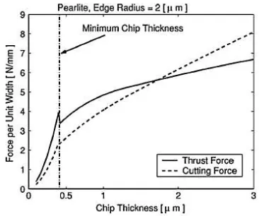
[image:4.612.339.522.280.433.2]orthogonal micromachining with the effect of the tool edge radius. Their FE analysis showed good agreement with experimental cutting of copper with a sharp diamond tool. Determined the minimum chip thickness of steel by using an FE simulation tool. They reported the critical chip thickness is 0.2 and 0.3 times the edge radius for pearlier and ferrite, respectively. Experimentally examined chip formation and micro-cutting forces. They concluded that a sudden change in thrust forces could be used to determine the minimum chip thickness. This sudden change in thrust forces was explained by a shifting from plowing/ sliding dominant forces to shearing dominant forces as shown in Fig. 2.
Fig. 2. Chip load and force relationship for Pearlite.
Cutting forces in micro-machining
The cutting force is directly related to chip formation. The cutting force also determines the tool deflection and bending stress that limits the feed rate. Well developed analytical cutting force models help operators choose the right cutting conditions for their system. There are two components to cutting forces namely, shearing and plowing forces. Since the chip thickness in micromachining applications can be comparable in size to the edge radius of the tool, the conventional sharp-edged theorem cannot be applied in micro-machining operations due to their large negative rake angle. In addition, the elastic-plastic deformation of the work piece also changes the cutting forces in micro-machining operations.
(Kim et al., 1998). Showed analytically the differences in
that the cutting forces are different from the sharp-edge model. Found that the forced vibration of the tool and the elastic recovery of the work piece contribute to the magnitude of the cutting force at low feed rates. They proposed the micro-end milling process as having three types of mechanisms: only elastic deformation (the UN cut chip thickness is smaller than the minimum chip thickness); elastic and shearing deformation; and, shearing deformation (the uncut chip thickness is greater than the minimum chip thickness). They have used the elastic recovery rate, based on the results from
(Mahendrakar et al., 1998). Work in order to quantify
different types of deformations. In addition, also investigated the effect of low feed rate. They performed cutting at various feed rates and found that very low feed rates resulted in instability due to the elastic deflection of the work piece. This, in turn, creates variation in chip thickness, which results in chatter. Depicts the instability at different feed rates, where the second and third row graphs show the instability. Investigated the effect of static tool deflection by assuming the tool as a simple cantilever beam. Their model corrected the actual depth of cut by subtracting the deflection of the cutting tool from the commanded depth of the cut. Compensated for the deflection errors in micro-tools by predicting the cutting and thrust forces. Since at micro-scales, cutting force influences tool deflection and tool deflection influences the cutting force,
cutting force models should include this coupling. (Fang et al.,
2000) developed an analytical micro-machining cutting force model for the calculation of chip thickness by considering the trajectory of the tool tip, but did not consider the negative rake angle effect, elastic-plastic work piece, or the deflection of tool (they used relatively large diameter tools). According to the authors, it is not desirable to apply conventional macro-models to the micro-machining process when the ratio between the feed per tooth to tool edge radius is greater than 0.1. In micro-mechanical machining, the depth of cut is often less than the critical minimum chip thickness to avoid tool breakage and to maintain desired tolerances. This causes a large negative rake angle between the tool and work piece. Conventional sharp-edge macro-cutting models cannot be used to predict cutting forces in micro-machining applications. In addition, the work piece material’s elastic plastic effects and the static deflection of the tool cannot be discounted in micro-cutting force analysis.
Effect of work piece material (grain size)
In micro-machining, the nature of the work piece must be considered in order to fabricate accurate micro-parts,
(Tansel and Arkan, 1998) As the depth of cut is sometimes less than the grain size in the work piece material. The assumption of homogeneity in work piece material properties is no longer valid. Because Micro-grain-structure size is often of the same order of magnitude as the cutter radius of curvature, the grain structures will affect the overall cutting properties. This is a distinct difference between micro- and macro mechanical machining. The assumption in macro-mechanical machining is always that the materials are isotropic and homogenous. The changing crystallography during the cutting process also causes variation in the micro-cutting force and generates vibration. This vibration is difficult to eliminate by changing the machine tool design or process conditions, because it originates from the work piece. Therefore, an averaged constant cutting coefficient cannot e used for micro-machining applications due to tool geometry, small grain size, and non-uniformity of the work piece material. Examined vibration caused by no homogeneous materials (i.e. aluminum single crystal with in precision
machining operations. They found that changing
crystallography and grain orientation affects shear angle and strength. (Takeuchi and Sakaida, 2003) Analyzed the cutting force in turning-related to work piece material and hardness. Using different aluminum and silicon alloys, they observed different microstructures significantly influence the magnitude of the cutting force, both in their static and dynamic components. When the cutting tool engages from one metallurgical phase to another, the cutting conditions change, causing machining errors, vibration, or accelerated tool wear.
Tool wears and burrs
The small depth of cut in micro-machining significantly increases friction between the tool and the work piece, resulting in thermal growth and wear. As a result, the increased radius of the tool decreases the quality of the produced part and increases the rate at which tools fail. In addition, the suppression of burr development in micro-machining is very important because unlike in macro-machining, post-processing cannot always be applied to remove burrs on miniature fabricated parts. While tool wear monitoring has been extensively studied on the macro-scale, very limited work has been conducted at the micro-scale.
(Tansel et al., 1998) Developed neural networks to predict tool
wear using cutting force and wear data. The neural networks estimated tool condition in the micro-machining of aluminum and steel, with slower tool wear rates for aluminum than in steel. This phenomenon is in agreement with tool wear in the soft/hard work piece cutting the neural network approach requires extensive experimental data and is often inconsistent
for different material and cutting conditions. (Rahman et al.,
2000) Investigated the micro turning of copper. They
wear, the edge of the cutting tool becomes flat. This flat area can be monitored with a scanning electron microscope (SEM) image of the tool edge. However, the applicability of this method is limited by the long and difficult set-up of the SEM. The influence of the tool size on tool wear was investigated
who also used an SEM to measure the tool wear. (Tonshoff,
1998) investigated the relationship between the coolant pressure and tool wear in micro-machining. Their experimental results showed there is no relationship between the amount of wear and the coolant pressure. In milling, the kinematics of the tool as it exits from the work piece significantly affects burr formation due to plastic deformation (i.e. bending) of chips rather than shearing, reported that burrs frequently occur when micro-machining hard materials because of increased tool wear.
Conclusion
Nano- and micro-electro-mechanical systems (MEMs) are seen as the favored technology for component miniaturization, and its use promises to enhance economic growth, health, and quality of life. However, interfacing to the macro-domain has been a big challenge. Micromechanical cutting is an enabling technology that can bridge the gap between the macro- and nano/micro-domain. The flexibility and efficiency of turning processes using carbide tools allow the fabrication of small batches compared with other processes. In some cases, the removal of material shows similar trends between the macro- and micro-machining processes, such as regenerative chatter, tool wear, and monitoring strategies. However, in many instances, the direct scaling of macro-knowledge to the micro-domain was not successful. Rather, micro-fabrication requires extensive research in chip removal processes, cutting force predictions, handling, assembly, material properties, modeling and testing in order to provide accuracy and productivity in micro-scales. In addition, extensive commercialization of micro-engineering technology relies on low cost, fast cycle time and high dimensional accuracy production methods. Micro-injection molding processes to produce bio-MEMs are especially attractive, since this process would cost pennies instead of hundreds of dollars. Micro-mechanical machining is well suited to support the development of micro-injection molds because of its promise for accurate, low cost, small batch size processes of 3D molds using ferrous alloys. The
development of successful micro-mechanical cutting
technologies will provide a catalyst for the broader development of micro-engineered systems. The investigation of micro cutting processes is relatively new and further research is required to answer its many challenging questions.
REFERENCES
Alting, L., Kimura, F.,. Hansen, H.N. and Bissacco, G. 2003. Micro engineering, Annals of CIRP Keynote STC-O. Bang, Y.B., Lee, K. and Oh, S. 2004. 5-Axis micro milling
machine for machining micro parts, Advanced
Manufacturing Technology.
Kalpakjian, S. and Schmid, S.R. 2002. Manufacturing Processes for Engineering Materials, Prentice-Hall, New Jersey.
Kussul, E., Baidyk, T., Ruiz-Huerta, L., Caballero-Ruiz, A., Velasco, G. and Kasatkina, L. 2002. Development of
micro machine tool prototypes for micro factories. Journal
of Micromechanics and Micro engineering, 12: 795–812.
Kussul, E., Baidyk, T., Ruiz-Huerta, L., Caballero-Ruiz, A., Velasco, G. and Kasatkina, L. 1996. Micromechanical engineering: a basis of the low-cost manufacturing of
mechanical micro devices using micro equipment. Journal
of Micromechanics and Micro Engineering, 6:410–425.
Li, X., Lin, R., and Leow, K.W. 2000. Performance-enhanced micro-machined resonant systems with
two-degrees-of-freedom resonators. Journal of Manufacturing Science
and Engineering, 10: 534–539.
Liu, X., DeVor, R.E., Kapoor, S.G. and Ehman, K.F. 2004. The mechanics of machining at the micro scale:
assessment of the current state of the science. Journal of
Manufacturing Science and Engineering, 126:666–678.
Masuzawa, T. 2000. State of the art of micro machining, Annals of CIRP 49 (2): 473–488.
Merchant, M.E. 1945. Mechanics of the metal cutting process, ii. Plasticity conditions in orthogonal cutting.
Journal of Applied Physics, 16: 318–324.
Onikura, H., Ohnishi, O. and Take, Y. 2000. Fabrication of micro carbide tools by ultrasonic vibration grinding, Annals of CIRP 49.
Shabouk, S. and Nakamoto, T. 2003. Micro machining of single crystal diamond by utilization of tool wear during
cutting process of ferrous material. Journal of Micro
Mechatronics, 2 (1) :13–26.
Shaw, M.C. 1995. Precision finishing, Annals of CIRP 44 (1): 343– 348
Takeuchi, Y., Sakaida, Y., Sawada, K. and Sata, T. 2000. Development of a 5-axis control ultra precision milling machine for micromachining based on non-friction servomechanisms, Annals of CIRP.
Tanaka, M. 2001. Development of desktop machining
microfactory. Riken Review, 34: 46–49.
Tansel, I.N., Arkan, T.T., Bao, W.Y., Mahendrakar, N., Shisler, B., Smith, D. and McCool, M. 2000. Tool wear
estimation in micro-machining. Part 1, International
Journal of Machine Tools and Manufacture, 40:599–608.
Tansel, I.N., Nedbouyan, A., Trujillo, M. and Tansel, B. 1998. Micro-endmilling- extending tool life with a smart work piece holder, International Journal of Machine Tools and Manufacture 38: 1437–1448.
Tansel, I.N., Arkan, T.T., Bao, W.Y., Mahendrakar, N., Shisler, B.,. Smith, D and McCool, M. 2000. Tool wear estimation in micro-machining. Part 2:
neural-network-based periodic inspector for non metals, International
Journal of Machine Tools and Manufacture, 40 : 609–620.
Th. Schaller, L. Bohn, J. Mayer, K. Schubert, 1999. Microstructure grooves with a width of less than 50 mm
cut with ground hard metal micro end mills. Precision
Engineering, 23: 229–235.
Tonshoff, H.K. 1988. Developments and trends in monitoring and control of machining processes, Annals of CIRP 37 (2): 611–622.
Vogler, M.P., Liu, X., Kapoor, S.G., Devor, R.E. and Ehmann, K.F. 2002. Development of meso-scale machine tool (mMT) systems, Society of Manufacturing Engineers MS n MS02-181:1–9.
Weck, M., Fischer, S. and Vos, M. 1997. Fabrication of micro
components using ultra precision machine tools.