© 2019, IRJET | Impact Factor value: 7.34 | ISO 9001:2008 Certified Journal | Page 361
BENDING ANALYSIS OF FUNCTIONALLY GRADED BEAM CURVED IN
ELEVATION USING HIGHER ORDER THEORY
R.A. Sayyad
1, V.R. Rathi
2,
P.K. Kolase
31Post graduate student, Department of Civil Engineering, Pravara Rural Engineering College Loni, India-413736 2Professor, Department of Civil Engineering, Pravara Rural Engineering College Loni, India-413736 3Professor, Department of Civil Engineering, Pravara Rural Engineering College Loni, India-413736
---***---
ABSTRACT:-
This paper presents bending analysis of functionally graded beam curved in elevation using higher order theory, which includes both shear deformation and thickness stretching effects. Various symmetric and non-symmetric sandwich beams with FG material in the core or skins under the uniformly distributed load are considered. MATLAB code and Navier solutions are developed to determine the displacement and stresses of FG sandwich beams for various power-law index, skin-core-skin thickness ratios and boundary conditions. Numerical results are compared with those predicted by other theories to show the effects of shear deformation and thickness stretching on displacement and stresses.Keywords: Functionally Graded, Sandwich beam, Navier solution, Numerical Analysis
1. INTRODUCTION
The concept is to make a composite material by varying the microstructure from one material to another material with a specific gradient. This enables the material to have the best of both materials. If it is for thermal, or corrosive resistance or malleability and toughness both strengths of the material may be used to avoid corrosion, fatigue, fracture and stress corrosion cracking. The transition between the two materials can usually be approximated by means of a power series. Beams can be analysed using classical beam theory, Timoshenko beam theory and equivalent single layer theories [1-11].
for the linear static analysis of functionally graded beams via a unified formulation. It is observed that Bernoulli-Euler and Timoshenko theories are the particular cases of a unified formulation. A Navier type, closed form solution is obtained for bi-directional FGM beam.
1.1 Functionally graded materials
There are two types of graded structures which can be prepared in case of FGM, continuous structure and stepwise structure In case of continuous graded structure, the change in composition and microstructure occurs continuously with position on the other hand in case of stepwise, microstructure feature changes in stepwise manner, giving rise to a multi-layered structure with interface existing between discrete layers.
1.2 FGM Application
FG materials are preferred due to delamination, matrix cracks, stress concentration and other damage mechanisms which are often observed in fibrous composite laminates. Most commonly used FG materials are ceramic and metal. Functionally graded materials are having attractive properties such as high thermal resistance, high impact resistance, increases the bond strength and reduce the residual stress, thermal stress and crack driving forces. A low-cost ceramic-metal functionally graded material would be ideal for wear-resistant linings in the mineral processing industry. Such a material would comprise a hard ceramic face on the exposed side, a tough metal face on the rear side that can be bolted or welded to a support frame, and a graded composition from metal to ceramic in between. The gradation would enhance the toughness of the ceramic face and also prevent ceramic-metal de-bonding.
2. METHODOLOGY
Functionally graded curved sandwich beam under consideration
Fig.2.1 Functionally graded curved sandwich beam
Consider a functionally graded sandwich beam curved in elevation with length L and rectangular cross-section b × h, with b being the width and h being the height and with radius of curvature R.
2.1 Displacement fields
The displacement field of the present higher order shear deformation theory is given by,
0 0
0
1 ( )
( )
x
z
z w
u u z f z
R x
w w g z
© 2019, IRJET | Impact Factor value: 7.34 | ISO 9001:2008 Certified Journal | Page 363
0 0
0
x z
where, , are the axial and transverse displacements, ,
are the axial displacements of
a point on the neutral axis,
is bending slope and
, are the shear slopes.
u w
u w
w
x
2.2 Strains
The non-zero normal and transverse shear strains associated with the displacement field in equation are obtained within the framework of linear theory of elasticity,
2
0 0 0
2
0 0 0 0 0
( ) ( ) [ ( )] ( ) ( ) ( ) x z x z z z z
xz x x
u w u w w g z
z f z
x R x x x R R
w g z
z z
u w u u w w u
g z g z g z
z x R R x x x R x
(2)2.3 Stresses
The stress-strain relationship at any point in the beam is given by the two dimensional Hooke’s law as follows,
11 12 12 22
33
11 22 2 12 2 33
0
0
0 0
( ) ( ) ( )
(1 ) (1 ) 2(1 )
x x z z xz xz Q Q Q Q Q Q
E z E z E z
Q Q Q Q
(3)
where, xis normal stress,xz is transverse shear stress, E is Young’s modulus and
x is normal strain,
is Poisson’s ratio.2.4 Principle of virtual work
/ 2 0
0 0 / 2
L L h
x x z z xz xz
h
q w dx dzdx
/2 0 2 0 0
2 0 /2 ( ) ( ) L h x z x h
u w w g z
z f z dz dx
x x x R R
(4)2.5 Governing Equations
The governing equations can be obtained by integrating the derivatives of the varied quantities by parts and collecting the coefficients of
u0,
w0,
xand
z2.6 Method of solution
The Navier method is used for static analysis in the simply supported sandwich beam. Field can be assumed
0
0
cos
sin
cos
....where
(
/ )
sin
sin
mn mn x xmn z zmn mnu
u
x
w
w
x
x
m
L
x
q
q
x
(6)By substituting these equation into equations (5), four differential equations can be obtained as
11 12 13 14 21 22 23 24 31 32 33 34 41 42 43 44
K K K 0
K K K K
K K K K 0
K K K K 0
mn mn xmn zmn K u w q (7) Where , 2 3
11 11 12 11 11 21 2
13 11 31, 14 11 12 41
4 2 2
22 11 11 11
3
23 11 11 32
2 2
24 11 12 11 12 42
2
33 11 33, 34
, ( ( / ) )
( ( / ) )
2 ( / ) ( / )
( ( / ) )
( ( / ) ) ( / ) ( / )
K A K B A R K
K C K K K R D K
K E B R A R
K F C R K
K M R G AK R D R K
K H L K
11 12 33 43
2 2 2 2 2 2
44 11 12 22 33
( ( / ) )
( / ) 2 ( / )
N R I L K
K L R O R J L
(8)
3. NUMERICAL RESULTS AND DISCUSSION
The material properties of metal, ceramic and FGM layers are as the following
Emetal = 70 GPa and Eceramic = 380 GPa
Non-dimensional maximum axial and transverse deflection of the beam are considered as
3 3 4 4 0 0 100 100 , m m N N
E h E h
U U W W
L Q L Q
Non-dimensional maximum axial and shear stresses of the beam are considered as
0 0 0
and
x z zx
Nx Nz N
h h h
LQ LQ LQ
Table 1: The maximum transverse deflection of single layer FG curved beam
L/h p w
R=5 R=10 R=20 R=50 R=100 Straight beam
5 0 2.4776 2.4778 2.4778 2.4778 2.4778 2.4778
1 4.8587 4.8456 4.8391 4.8352 4.8339 4.8326
© 2019, IRJET | Impact Factor value: 7.34 | ISO 9001:2008 Certified Journal | Page 365 Table 2: The maximum normal stress xof single layer FG curved beam
Table 3: The maximum normal stress z of single layer FG curved beam
L/h P
R=5 R=10 R=20 R=50 R=100 Straight
Beam
5 0 -0.3121 -0.3074 -0.3052 -0.3039 -0.3035 0.303
1 0.3211 0.3507 0.3656 0.3745 0.3775 0.3805
2 0.3696 0.407 0.4258 0.437 0.4408 0.4446
5 -0.3821 0.3932 0.4137 0.426 0.4302 0.4343
10 0.3683 0.4155 0.4393 0.4537 0.4584 0.4632
5 7.6173 7.5993 7.5904 7.585 7.5833 7.5815
10 8.5354 8.5148 8.5046 8.4985 8.4965 8.4944
10 0 2.3191 2.3192 2.3192 2.3193 2.3193 2.3193
1 4.592 4.5785 4.5717 4.5677 4.5664 4.5651
2 5.8515 5.8341 5.8255 5.8204 5.8187 5.817
5 6.9954 6.977 6.9679 6.9624 6.9606 6.9588
10 7.7705 7.7495 7.739 7.7327 7.7307 7.7286
100 0 2.2664 2.2666 2.2666 2.2666 2.2666 2.2666
1 4.5034 4.4897 4.483 4.4789 4.4776 4.4762
2 5.727 5.7095 5.7009 5.6957 5.694 5.6923
5 6.7891 6.7705 6.7613 6.7558 6.754 6.7522
10 7.5167 7.4955 7.4849 7.4786 7.4765 7.4744
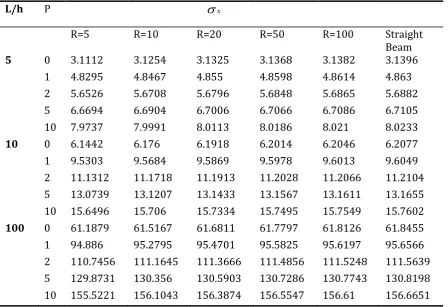
L/h P
R=5 R=10 R=20 R=50 R=100 Straight
Beam
5 0 3.1112 3.1254 3.1325 3.1368 3.1382 3.1396
1 4.8295 4.8467 4.855 4.8598 4.8614 4.863
2 5.6526 5.6708 5.6796 5.6848 5.6865 5.6882
5 6.6694 6.6904 6.7006 6.7066 6.7086 6.7105
10 7.9737 7.9991 8.0113 8.0186 8.021 8.0233
10 0 6.1442 6.176 6.1918 6.2014 6.2046 6.2077
1 9.5303 9.5684 9.5869 9.5978 9.6013 9.6049
2 11.1312 11.1718 11.1913 11.2028 11.2066 11.2104
5 13.0739 13.1207 13.1433 13.1567 13.1611 13.1655
10 15.6496 15.706 15.7334 15.7495 15.7549 15.7602
100 0 61.1879 61.5167 61.6811 61.7797 61.8126 61.8455
1 94.886 95.2795 95.4701 95.5825 95.6197 95.6566
2 110.7456 111.1645 111.3666 111.4856 111.5248 111.5639
5 129.8731 130.356 130.5903 130.7286 130.7743 130.8198
10 155.5221 156.1043 156.3874 156.5547 156.61 156.6651
x
z
10 0 -0.456 -0.4456 -0.4406 -0.4377 -0.4367 0.4358
1 -0.6581 -0.6404 -0.6314 -0.6259 -0.6241 -0.6222
2 -0.7472 -0.7295 -0.7205 -0.715 -0.7132 -0.7113
5 -0.6834 -0.6899 -0.6934 -0.6955 -0.6962 -0.6969
10 -0.5941 -0.6015 -0.6054 -0.6078 -0.6086 -0.6094
100 0 -4.0057 -3.8981 -3.8466 -3.8164 -3.8064 3.7965
1 -6.905 -6.73 -6.6404 -6.586 -6.5677 -6.5494
2 -7.7549 -7.5798 -7.4902 -7.4358 -7.4176 -7.3993
5 -6.5667 -6.6298 -6.663 -6.6834 -6.6903 -6.6972
[image:6.595.68.534.284.593.2]10 -5.61 -5.6812 -5.7188 -5.742 -5.7498 -5.7577
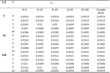
Table 4: The maximum shear stress xzof single layer FG curved beam
CONCLUSION:
Based on a higher order shear deformation theory, MATLAB code and Navier solutions are developed to determine the displacement and stresses of FG sandwich beams. This theory includes both shear deformation and thickness stretching effects. Single layer functionally graded straight and curved beams are considered. Numerical results are compared with those predicted by other theories to show the effects of shear deformation and thickness stretching on the displacement and stresses.
REFERENCES:
1. AS Sayyad, YM Ghugal Buckling and free vibration analysis of orthotropic plates by using exponential shear
L/h P
R=5 R=10 R=20 R=50 R=100 Straight
Beam
5 0 0.4914 0.4914 0.4914 0.4914 0.4914 0.4914
1 0.5317 0.5316 0.5316 0.5315 0.5315 0.5315
2 0.5501 0.55 0.55 0.5499 0.5499 0.5499
5 0.509 0.5089 0.5089 0.5089 0.5089 0.5089
10 0.4386 0.4385 0.4385 0.4385 0.4385 0.4385
10 0 0.4919 0.4919 0.4919 0.4919 0.4919 0.4919
1 0.5322 0.5321 0.5321 0.5321 0.5321 0.5321
2 0.5507 0.5507 0.5506 0.5506 0.5506 0.5506
5 0.5098 0.5097 0.5097 0.5097 0.5097 0.5097
10 0.4393 0.4392 0.4392 0.4392 0.4392 0.4392
100 0 0.4921 0.4921 0.4921 0.4921 0.4921 0.4921
1 0.5324 0.5323 0.5323 0.5322 0.5322 0.5322
2 0.551 0.5509 0.5508 0.5508 0.5508 0.5508
5 0.5101 0.51 0.51 0.5099 0.5099 0.5099
10 0.4395 0.4394 0.4394 0.4394 0.4394 0.4394
zx
© 2019, IRJET | Impact Factor value: 7.34 | ISO 9001:2008 Certified Journal | Page 367
2. Effect of stress concentration on laminated plates, Journal of Mechanics 29 (2), 241-252, 2013
3. AS Sayyad, Static flexure and free vibration analysis of thick isotropic beams using different higher order shear deformation theories, International Journal of Applied Mathematics and Mechanics 8 (14), 71-87, 2012
4. YM Ghugal, AS Sayyad Free Vibration of Thick Isotropic Plates Using Trigonometric Shear Deformation Theory, J Solid
Mech 3 (2), 172-182, 2011
5. AS Sayyad, Comparison of various shear deformation theories for the free vibration of thick isotropic beams
International Journal of Civil & Structural Engineering 2 (1), 85-97, 2011
6. AS Sayyad, YM Ghugal, On the free vibration of angle-ply laminated composite and soft core sandwich plates, Journal of
Sandwich Structures & Materials 19 (6), 679-711, 2017
7. SM Ghumare, AS Sayyad, A new fifth-order shear and normal deformation theory for static bending and elastic
buckling of P-FGM beams, Latin American Journal of Solids and Structures 14 (11), 1893-1911, 2017
8. AS Sayyad, YM Ghugal, PN Shinde, Stress analysis of laminated composite and soft core sandwich beams using a simple
higher order shear deformation theory, Journal of Serbian Society for Computational Mechanics 9 (1), 15-35, 2015
9. AS Sayyad, YM Ghugal, RR Borkar, Flexural Analysis of Fibrous Composite Beams under Various Mechanical Loadings
Using Refined Shear Deformation Theories, Composites: Mechanics, Computations, Applications: An International Journal, 2014
10. AS Sayyad, YM Ghugal, A nth-order shear deformation theory for composite laminates in cylindrical bending, Curved
and Layered Structures 2, 290-300, 2015
11. AS Sayyad, YM Ghugal, Static flexure of soft core sandwich beams using trigonometric shear deformation theory, Mechanics of dvanced omposite tructures 2 (1), 45-53, 2015.
12. Benatta, M.A., Tounsi, A., Mechab, I., Bouiadjra, M.B. “Mathematical solution for bending of short hybrid composite beams with variable fibers spacing”. Applied Mathematics Computation, 212, 337-348 (2009)
13. Benetta, M. ., Mechab, I. Tounsi, . Bedia, E. . . “ tatic analysis of functionally graded short beams including warping
and shear deformation effects”. Composite Materials Science, 44, 765-773 (2008)
14. Giunta G., Belouettar, ., arrera, E. “ nalysis of FGM beams by means of a unified formulation”. IOP Conference Series:
Materials Science and Engineering, 10, 1-10 (2010)
15. Jiang, .M., Ding, H.J. “The analytical solutions for orthotropic cantilever beams (II): olutions for density functionally
graded beams”. J. Zhejiang University Sci., 6A (3), 155-158 (2005)
16. Li, X.F. “ unified approach for analyzing static and dynamic behaviors of functionally sssgraded Timoshenko and Euler-Bernoulli beam”. J. Sound Vibrations, 318, 1210-1229 (2008)
17. Li, X.F., Wang, B.L., Han, J. . “ higher-order theory for static and dynamic analyses of functionally graded beams”. Applied Mechanics, 80, 1197-1212 (2010)
18. Nguyen, T.K., Vo, T.P., Thai, H.T. “ tatic and free vibration of axially loaded FG beams based on the first-order shear
deformation theory”. Composites Part B-Eng. 55, 147-157 (2013)
19. Sallai B.O., Abedlouahed, T., Ismail, M., Mohamed, B.B., Mustapha, M., bbas, .B.E. “ theoretical analysis of flexional
bending of Al/Al203 S-FGM thick beams”. Composite Material Science, 44(4), 1344-1350 (2009)
20. Thuc Vo, Huu-Tai Thai, Trung-Kien Nguyen, Fawad Inam, Jaehong Lee “ tatic behaviour of functionally graded