ISSN Online: 2327-6053 ISSN Print: 2327-6045
Evaluation of Performance of Thermal and
Electrical Hybrid Adsorption Chiller Cycles with
Mechanical Booster Pumps
Tao Zeng
1, Takehiro Esaki
1*, Jun Li
1, Noriyuki Kobayashi
1, Hongyu Huang
21Department of Chemical Engineering, Nagoya University, Nagoya, Japan
2Integrated Technology Center, Guangzhou Institute of Energy Conversion, Chinese Academy of Sciences, Guangzhou, China
Abstract
Large amounts of waste heat below 100˚C from the industrial sector are re-leased into the atmosphere. It has been suggested that energy system efficien-cy can be increased with adsorption chillers. However, the cooling power and coefficient of performance (COP) of conventional adsorption chillers signifi-cantly decrease with the desorption temperature. In this paper, we proposed a mechanical booster pump (MBP)-assisted adsorption chiller cycle, and eva-luated its performances. In the cycle, a MBP was incorporated into a zeo-lite-water-type adsorption chiller for facilitating water vapor transportation between an adsorber and an evaporator/condenser. We have experimentally studied the effect of the input electrical power of MBP on the performances of adsorption chiller cycle. It has been demonstrated that the heat input achieved by using MBP at the desorption temperature of 50˚C was 1.6 times higher than that of without MBP at the desorption temperature of 60˚C. And the in-crease of pump power was found to be effective in increasing the heat input. Therefore, it was confirmed that the operation range of desorption tempera-ture, which can be generated by using the waste heat, was extended and the cooling power was increased directly by using MBP.
Keywords
Adsorption, Chiller Cycle, Zeolite/Water Pair, Mechanical Booster Pump
1. Introduction
Since the Industrial Revolution, energy consumption has increased. This has led to an increase in the amount of industrial waste heat as well. Cogeneration sys-tems have attracted increasing attention over the past two decades due to the
How to cite this paper: Zeng, T., Esaki, T., Li, J., Kobayashi, N. and Huang, H.Y. (2017) Evaluation of Performance of Ther- mal and Electrical Hybrid Adsorption Chiller Cycles with Mechanical Booster Pumps. Journal of Materials Science and Chemical Engineering, 5, 22-32.
https://doi.org/10.4236/msce.2017.55003
Received: February 21, 2017 Accepted: May 24, 2017 Published: May 27, 2017 Copyright © 2017 by authors and Scientific Research Publishing Inc. This work is licensed under the Creative Commons Attribution International License (CC BY 4.0).
http://creativecommons.org/licenses/by/4.0/
high energy efficiency (e.g. 80% when a gas turbine with waste heat boiler is used). The energy efficiency of cogeneration system can also be improved with the use of a heat energy conversion apparatus. Adsorption chiller, as one of the heat energy conversion apparatus, can use low-temperature heat source of 60˚C - 100˚C to generate the desired cooling effect for reducing air-conditioning loads. The refrigeration cycle generates the cooling effect by means of adsorp-tion, absorpadsorp-tion, and chemical reaction phenomena [1][2][3]. In particular, the adsorption chiller cycle has recently been receiving a lot of attention. The ad-sorption chiller cycle can be used to store waste heat and supply cold energy at low temperatures. Water-zeolite [4], Water-silica gel and Ammonia-activated carbon pairs [5] are some of the most common refrigerant-adsorbent pairs used in adsorption chillers. An adsorption chiller cycle using H2O or NH3 refrigerant
is considered to be an environment-friendly product. In a previous study, Kaki-uchi et al. [6] introduced a new Functional Adsorbent Material-Zeolite 01 (FAM-Z01), which is an AFI-type structure Ferroaluminophoshate Zeolite (FAPO-5) with iron content of 2 - 8 mol% [6]. It was suggested that the adsorp-tion capacity of FAM-Z01 was four times than that of silica gel at a desorpadsorp-tion temperature of 60˚C. However, the adsorption chiller cycle still has a few prob-lems in practical use; by reason of the cooling power per unit volume of the ad-sorber and the COP are smaller than that of absorption chiller or vapor com-pression chiller.
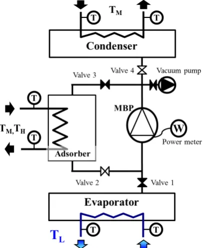
To solve the problems associated with the adsorption chiller cycle, we pro-posed a hybrid adsorption chiller which contained a mechanical booster pump (MBP) in the adsorption step or desorption step. Figure 1 shows the schematic diagram of the hybrid adsorption chiller cycle. It consists of an evaporator, a condenser, a MBP and an adsorber. All the units are connected under reduced pressure. The MBP is set either between the evaporator and the adsorber or be-tween the adsorber and the condenser. The adsorption core which is installed in the adsorber consists of a heat exchanger filled with adsorbents. The heat asso-ciated with the adsorption or desorption phenomenon is removed or supplied by heat exchanger. The adsorption chiller cycle consists of an adsorption step and a desorption step. In the adsorption step, the refrigerant vapor moves from the evaporator to the adsorber, and then be adsorbed. In the desorption step, the desorption heat is supplied to the adsorber, and the desorbed refrigerant vapor moves to the condenser. In the hybrid cycle, MBP, which runs on electricity, pumps the refrigerant vapor from the evaporator to the adsorber to increase the adsorber pressure of vapor in adsorption cycle or pumps the refrigerant vapor from the adsorber to the condenser to decrease the adsorber pressure of vapor in desorption cycle. The change of pressure improves the adsorbent capacity.
Figure 1. Schematic diagram of hybrid adsorption chiller cycle with MBP.
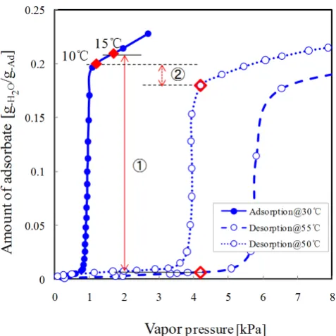
Figure 2. Adsorption isotherms of water on FAM-Z05.
the evaporator at the saturation pressure of 1.2 kPa can be compressed by the MBP, when the adsorber pressure rises to 1.7 kPa, the amount of adsorption is increased and has the same value as the condition that the evaporator tempera-ture is 15˚C without MBP. In the hybrid desorption cycle, desorption can take place when the vapor pressure of the adsorber is depressurized to 1 kPa at 50˚C by MBP. The amount of desorption is equal to that of desorption under the con-dition of desorption temperature is 55˚C without MBP. In this way, we can use MBP to expand the amount of adsorption or desorption by increasing or de-creasing the vapor pressure of the adsorber. Therefore, the hybrid chiller cycle can be used at a large range of operation temperatures.
[image:3.595.254.493.282.521.2]We evaluated the cooling output and desorption heat input of the hybrid chiller cycle, and researched the effect of the input electrical power of the MBP on the performances of hybrid cycle.
[image:4.595.272.477.295.544.2]2. Experimental Procedure
Figure 3 shows the schematic diagram of the experimental apparatus. Falling liquid film heat exchangers were used in the evaporator and the condenser, which had high heat transfer performance. Figure 4 shows the adsorption cores in the adsorber. Three pairs of adsorption cores were connected in series in the adsorber, and each pair was composed of two flat webbed tube and corrugated fin heat exchangers in parallel and FAM-Z05, had an average particle diameter of 5 μm, was coated around the tubes and fins of heat exchangers by epoxy binder. The coating thickness of adsorbent was 100 μm. MBP (MBS-052 type, ULVAC Inc.) was connected with stainless tubes and the rotating speed was
[image:4.595.289.462.576.715.2]Figure 3. Schematic diagram of the experimental apparatus.
Table 1. Experimental conditions.
Step Adsorption Step Desorption Step Evaporator 10˚C, 15˚C 15˚C Adsorption temperature 30˚C 30˚C Desorption temperature 60˚C 60˚C, 55˚C, 50˚C, 45˚C
Condenser 30˚C 30˚C MBP power 20, 60, 100 W 50, 60, 100 W
controlled by Lab View (National Instrument Inc.). When MBP was driven, we measured the electrical power consumption of it.
The experimental conditions are summarized in Table 1. The condenser temperature was maintained at 30˚C by thermostat bath. The evaporator tem-perature was set at 10˚C and 15˚C. The desorption temtem-perature was set at 45˚C, 50˚C, 55˚C and 60˚C.The flow rate of the heat transfer fluid of all the units was set at a constant value of 4.5 L/min. The temperature of the fluid flow was meas-ured by a Platinum resistance temperature sensor. This was followed by the cal-culation of cooling heat output, desorption heat input, amount of cooling heat and desorption heat and COPelectricity using the following equations:
fluid fluid fluid ,average
EVA EVA
W =Cp ⋅ρ ⋅F ⋅ ∆T (1)
desorption fluid fluid fluid desorption,average
W =Cp ⋅ρ ⋅F ⋅ ∆T (2)
desorption 0 desorptiond t
EvA or EVA or
Q =
∫
W t (3)electricity
electricity
EVA
Q COP
Q
= (4)
3. Experimental Results and Discussion
3.1. Adsorption Step
Figure 5. Time variation of cooling heat output for different MBP powers at 15˚C (a) and 10˚C (b).
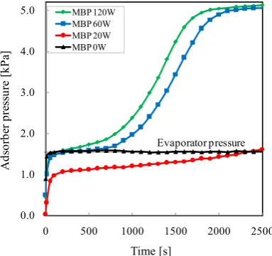
Figure 6. Effect of MBP power on the adsorber pressure in adsorption step.
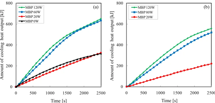
pressure was 2300 s at 20 W. The vapor transport between the evaporator and the adsorber was hampered by MBP, due to the rotational speed of MBP was ex-tremely low at 20 W. It resulted in a very slow vapor transport rate, which was slower than that of without MBP and the adsorption rate. Figure 7 shows the amount of cooling heat in the adsorption step. As can be seen from the results, the amount of cooling heat obtained with MBP was more than twice as much as that of without MBP at 15˚C. Furthermore, it was possible to obtain cooling heat at the evaporator temperature of 10˚C, which cannot be acquired without MBP. Therefore, the hybrid cycle with MBP can improve the cooling heat at low eva-porator temperature was confirmed. Figure 8 shows the effect of input electrical power of MBP on COPelectricity which is the ratio of the cooling heat to the input
electrical power of MBP. As can be seen from the results, the COPelectricity
de-creased with increasing the input electrical power of MBP. When the evaporator temperature was 15˚C, the COPelectricity for the input electrical power of 20, 60,
and 120 W was 7.0, 5.0 and 3.0, respectively. In addition, the COPelectricity at the
evaporator temperature of 10˚C exhibited the same tendency as the results of
0 100 200 300 400
0 500 1000 1500 2000 2500
MBP 120W MBP 60W MBP 20W MBP 0W Time [s] C ool ing he at out put [W ] (a) 0 100 200 300 400
0 500 1000 1500 2000 2500
MBP 120W MBP 80W MBP 20W Time [s] C ool ing he at out put [W ] (b) 0.0 1.0 2.0 3.0 4.0 5.0
0 500 1000 1500 2000 2500
[image:6.595.277.469.281.461.2]Figure 7. Time variation of cooling heat for different MBP powers at 15˚C (a) and 10˚C (b).
Figure 8. Effect of MBP power on the COPelectricity at the evaporator temperature of 15˚C (a) and 10˚C
(b).
15˚C. When the input electrical power of MBP was high, the COPelectricity of the
hybrid cycle was less than or equal to that of mechanical chiller cycle. Due to the saturation pressure of water is lower than the conventional refrigerants, such as HFC and ammonia, which are commonly used in the mechanical chiller.
Figure 9 shows the effect of the input electrical power of MBP on the maxi-mum cooling heat output and COPelectricity at the evaporator temperature of 15˚C.
As shown in Figure 9, the cooling heat output increased as the input electrical power of MBP increased, whereas the COPelectricity displayed the opposite trend.
The tradeoff between cooling heat output and COPelectricity was thus confirmed.
3.2. Desorption Step
We also studied the desorption step without and with MBP. The experimental apparatus was the same as that of the adsorption step. The desorption step was carried out after the adsorption step which had been conducted under the eva-porator temperature of 15˚C without MBP. Closed the valve 1 and 3, and then
0 200 400 600 800
0 500 1000 1500 2000 2500
MBP 120W MBP 60W MBP 20W MBP 0W Time [s] A m ount of c ool ing he at out put [kJ ] (a) 0 200 400 600 800
0 500 1000 1500 2000 2500
MBP 120W MBP 80W MBP 20W Time [s] A m ount of c ool ing he at out put [kJ ] (b) Time [s] 0.0 1.0 2.0 3.0 4.0 5.0 6.0 7.0 8.0
0 500 1000 1500 2000 2500
MBP 120W MBP 60W MBP 20W C OP ele ctr ic ity [-] (a) (b) Time [s] 0.0 1.0 2.0 3.0 4.0 5.0 6.0 7.0 8.0
0 500 1000 1500 2000 2500
increased the adsorber temperature from the adsorption temperature to the de-sorption temperature. When the adsorber pressure became equal to or higher than the condenser pressure, valve 3 and 4 were opened so that the refrigerant vapor can transport into the condenser spontaneously. On the other hand, when the MBP was running and the valve 2 and 4 were opened instead of valve 3 and 4, the refrigerant vapor was compressed into the condenser by MBP. The de-sorption temperature was set at 50˚C and 60˚C for the cycle without MBP, 55˚C, 50˚C and 45˚C for the cycle with MBP.
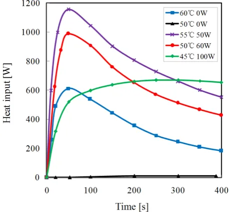
[image:8.595.258.488.505.716.2]Figure 10 shows the variation of desorption heat input with time. 0 s of the horizontal axis corresponds to the timing of valve opening and MBP running. The results show that the desorption of refrigerant could proceed without MBP at 60˚C, reaching a maximum desorption heat input of approximately 600 W. However, no desorption heat input can be obtained at 50˚C without MBP, due
Figure 9. Effect of MBP power on the cooling heat output and the COPelectricity at 15˚C.
Figure 10. Time variation of desorption heat input for different MBP powers.
0 2 4 6 8
100 150 200 250 300 350 400
20 40 60 80 100 120
Cooling heat output COP electricity
Electrical power [W]
C
ool
ing
he
at
out
put
[W
]
C
OP
ele
ctr
ic
ity
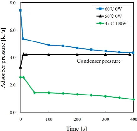
to the poor adsorption capacity at this desorption temperature as can be seen from Figure 2. On the other hand, high desorption heat input was obtained with MBP at the desorption temperature of 50˚C and 55˚C. When the input electrical power of MBP was 50 W, the maximum desorption input power of about 1150 W was obtained at 50˚C, which was higher than that of at 60˚C without MBP. The higher the input electrical power of MBP the lower the desorprion temper-ature can be used. Figure 11 shows the adsorber pressure change during desorp-tion step. In the desorpdesorp-tion step, the vapor transport rate is propordesorp-tional to the pressure difference between the absorber and condenser. As can be seen from
Figure 11, when valve 3 and 4 were opened, the adsorber pressure decreased to the condenser pressure immediately at 60˚C without MBP and the desorption heat input was obtained. However, due to the adsorber pressure at 50˚C was lower than the condenser pressure, when valve 3 and 4 were opened, the refrige-rant vapor transported from condenser to adsorber, the opposite transport di-rection to 60˚C, resulted in the desorption of refrigerant could not proceed and no heat input was obtained. It would have been the same situation as at 50˚C if MBP had not been used in the desorption step at 45˚C. When MBP was operat-ing at 100 W, the vapor from adsorber was compressed into condenser by MBP, and therefore the desorption heat input was acquired at 45˚C.
Figure 12 shows the amount of desorption heat. From Figure 12, it can be seen that the desorption heat could be obtained in less time by operating the MBP with an input electrical power of 100 W, at the low desorption temperature of 45˚C. Thus, we confirmed that in comparison with the cycle without MBP, hybrid cycle could obtain cooling heat at lower desorption temperature.
4. Conclusion
We assembled a lab-scale FAM-Z05/H2O type adsorption chiller cycle with and
without MBP. The effect of the input electrical power of MBP on the perfor-
Figure 12. Time variation of amount of desorption heat for different MBP powers.
mances of adsorption step and desorption step were investigated separately. The following results were obtained.)
1) Adsorption step with MBP
The cooling heat output and the amount of cooling heat were improved and increased with the input electrical power of MBP. Moreover, the adsorption chiller could be operated at a lower evaporator temperature lever. On the other hand, COP electricity decreased with increasing the input electrical power of MBP and was less than or equal to mechanical chiller cycle at the high input electrical power.
2) Desorption step with MBP
The desorption heat input and the amount of heat input were improved and increased with the input electrical power of MBP. Desorption cycle could be ef-fectively driven by a relatively low desorption temperature such as 45˚C, in comparison with the cycle without MBP.
The future work will be focused on the evaluation of cooling heat output and COP electricity when using MBP in the desorption step. A two-adsorber adsorp-tion chiller will be constructed, which one adsorber is in adsorpadsorp-tion cycle with MBP, the other one is in desorption cycle with MBP simultaneously. The per-formances of it will be investigated.
References
[1] Wu, W., Wang, B., Shi, W. and Li, X. (2014) Absorption Heating Technologies: A
Review and Perspective. Applied Energy, 130, 51-71.
https://doi.org/10.1016/j.apenergy.2014.05.027
[2] Demir, H., Mobedi, M. and Ülku, S. (2008) A Review on Adsorption Heat Pump:
Problems and Solutions. Renewable and Sustainable Energy Review, 12, 2381-2403.
https://doi.org/10.1016/j.rser.2007.06.005
[3] Lahmidi, H., Mauran, S. and Goetz, V. (2006) Definition, Test and Simulation of
80, 883-893. https://doi.org/10.1016/j.solener.2005.01.014
[4] Palomba, V., Vasta, S., Giacoppo, G., Calabrese, L., Gulli, G., La Rosa, D. and Freni,
A. (2015) Design of an Innovative Graphite Exchanger for Adsorption Heat Pumps
and Chillers. Energy Procedia, 81, 1030-1040.
https://doi.org/10.1016/j.egypro.2015.12.112
[5] Hirota, Y., Kobayashi, N., Watanabe, F., Hasatani, M., Uda, S. and Inaoka, H.
(2008) Development of the Adsorber in the Ammonia and AC Combination
Ad-sorption Heat Pump. Journal of Japan Society of Energy and Resources, 29, 35-41.
http://www.jser.gr.jp/journal/journal_pdf/2008/journal200805_6.pdf
[6] Kakiuchi, H., Shimooka, S., Iwade, M., Oshima, K., Yamazaki, M., Terada, S.,
Wa-tanabe, H. and Takewaki, T. (2005) Novel Water Vapor Adsorbent FAM-Z01 and
Its Applicability to an Adsorption Heat Pump. Kagaku Kogaku Ronbunshu (Japan),
31, 361-364. https://doi.org/10.1252/kakoronbunshu.31.361
Submit or recommend next manuscript to SCIRP and we will provide best service for you:
Accepting pre-submission inquiries through Email, Facebook, LinkedIn, Twitter, etc. A wide selection of journals (inclusive of 9 subjects, more than 200 journals)
Providing 24-hour high-quality service User-friendly online submission system Fair and swift peer-review system
Efficient typesetting and proofreading procedure
Display of the result of downloads and visits, as well as the number of cited articles Maximum dissemination of your research work
Submit your manuscript at: http://papersubmission.scirp.org/