ISSN Online: 1947-3818 ISSN Print: 1949-243X
DOI: 10.4236/epe.2019.1111024 Nov. 18, 2019 363 Energy and Power Engineering
Experiments Using
Capillary Mat as Ground Heat
Exchanger for Ground Source
Heat Pump Heating Application
Arif Widiatmojo
1*, Shrestha Gaurav
1, Takeshi Ishihara
1, Akira Tomigashi
1, Kasumi Yasukawa
2,
Youhei Uchida
1, Shohei Kaneko
1, Mayumi Yoshioka
11Renewable Research Center, National Institute of Advanced Industrial Science and Technology, Koriyama, Japan
2Japan Oil, Gas and Metals National Corporation (JOGMEC), Tokyo, Japan
Abstract
The cooling and heating of spaces are among the largest sources for house-hold’s energy demand. Ground Source Heat Pump (GSHP) is a promising technology to reduce the energy for cooling and heating purposes. However, the major obstacle hindering the utilization of this technology is the high ini-tial cost, especially for the installation of ground coupled heat exchanger. The horizontal closed-loop system offers lower installation cost, as it requires no vertical borehole construction. Instead, the heat exchangers can be installed in shallow trenches that may be excavated, by small excavator or even by hu-man labor. This paper presents the comparison of two different heat exchang-ers, namely, the capillary mat and the widely used slinky pipe. Both heat ex-changers are connected to a heat pump, where continuous heating tests were carried out for 165 hours (~7 days) for each configuration. The purpose of this research is to show the performance of capillary mat in comparison to slinky pipe. Despite during the entire test for capillary mat required 6% high-er electricity consumption, compared to slinky heat exchanghigh-er, the results still suggest the potential use of capillary mat as alternative to slinky heat ex-changer. Additionally, the results also highlight the high hydraulic resistance of installed capillary mat heat exchangers may become the major disadvan-tage of the capillary mat.
Keywords
Horizontal Heat Exchanger, Ground Source Heat Pump, Capillary Mat
How to cite this paper: Widiatmojo, A., Gaurav, S., Ishihara, T., Tomigashi, A., Yasu-kawa, K., Uchida, Y., Kaneko, S. and Yoshi-oka, M. (2019) Experiments Using Capillary Mat as Ground Heat Exchanger for Ground Source Heat Pump Heating Application. Energy and Power Engineering, 11, 363-378.
https://doi.org/10.4236/epe.2019.1111024
Received: October 2, 2019 Accepted: November 15, 2019 Published: November 18, 2019 Copyright © 2019 by author(s) and Scientific Research Publishing Inc. This work is licensed under the Creative Commons Attribution International License (CC BY 4.0).
http://creativecommons.org/licenses/by/4.0/
DOI: 10.4236/epe.2019.1111024 364 Energy and Power Engineering
1. Introduction
The Ground Source Heat Pump (GSHP) has been widely used as an alternative way to reduce the electricity consumption for space cooling and heating [1] [2]. Unlike the conventional Air Source Heat Pump (ASHP), which uses ambient air, GSHP utilizes stable ground temperature, as heat source or heat sink. Ground temperature has a relatively stable temperature due to its high heat capacity, in contrast to fluctuating air temperature. In area where ASHPs are extensively used, such as big cities, extensive use of ASHP for cooling in summer season could accelerate the heat island effect [3] [4] [5] [6]. This is a phenomenon where the air temperature is significantly higher than its surrounding area because of higher heat in-flux and lower heat dissipation. Kakegawa et al., in 2002, studied that the replacement of ASHP with GSHP in Wast-Shinjuku area, Tokyo, could reduce 54% of CO2 emission on the area [3]. Kardinal Yusuf et al. investigated
the relationship between industrial urban and commercial land use with the in-creasing urban heat island in Singapore [5]. Arifwidodo et al. investigated the household energy consumption and its impacts on the urban heat island in Bangkok area [6]. Further, they concluded that the combination of urban heat island mitigation, adaptation planning and energy-efficient housing design would contribute to better solutions.
The GSHP system can be expected to be an alternative to solve this problem. However, the growth of GSHP utilization is relatively slow as a result of high ini-tial cost. Most of the iniini-tial costs arise from the installation of ground heat ex-changer [7] [8] [9] [10]. In the closed-loop GSHP system, there are mainly two classifications of ground heat exchanger configuration, namely, vertical and ho-rizontal configurations. Vertical configuration allows higher heat rejection and/or extraction rate by the groundwater advection. However, the drilling of borehole is the highest cost for most cases. On the other hand, GSHP with horizontal ground exchanger is cheaper, as the heat exchanger can be installed in a shallow trench. The trench is typically 1 - 2 meters depth, which only requires small ex-cavators, or even direct excavation by human labor [11]. However, soils in shal-low depths are affected by the atmospheric temperature, soil thermal properties, depth and climatic conditions [12] [13] [14]. Thus, a careful assessment and plan-ning must be carried out prior to the installation.
DOI: 10.4236/epe.2019.1111024 365 Energy and Power Engineering Unlike the slinky or helical ground heat exchangers which are very popular, the use of capillary mat as ground heat exchanger is still limited. Most of the re-searches focus on the application of capillary mat for radiant heat exchanger in-side buildings [17] [18] [19] [20]. Zhou and He evaluated the thermal perfor-mance of radiant floor system with various heat storage materials and heat ex-changer pipes [17]. They showed that the capillary mat provides more uniform temperature and achieves it in a significant shorter time, in comparison to po-lyethylene coils. Further, their results suggested that the combination of capillary mat and phase change material (PCM) provides advantages over another system. Xia and Zhang showed potential cost reduction by proposing a new double-layer radiant floor system with organic phase change material for heat storage during summer and heat source in winter [18]. Capillary mat heat exchangers are pop-ular among other heat exchangers, such as, copper pipe, for its easy installation, lower cost [19]. Carbonell et al., develop a numerical model for ice storage by using capillary mat heat exchangers. Their numerical model was validated with the experimental results for both cooling and heating stages. Further, they also pointed out the robustness and reliability of the capillary mats for the given low temperature test condition, although longer test periods need to be carried out to evaluate its long-term reliability [20]. Zhao et al. presented the comparison be-tween capillary mat radiant and floor radiant heating system by ASHP system in residential building. The result showed that capillary mat radiant consumed 45% less electricity than floor radiant heating system [21]. The use of capillary mat incorporated into ceramic panel and passive cooling system in Mediterranean housing was studied by Echarri [22]. To the best of author’s knowledge, technic-al applications of capillary mat as ground heat exchanger are very limited, for instance in China [23] and Europe [24].
Compared to the HDPE pipe-based ground heat exchangers, capillary mat al-lows simple installation and transportation as it requires no on-site loop prepa-rations. In addition, small capillary tubes provide more heat transfer area availa-ble per unit footprint of installation area, which is important for installation in space-limited area.
This study presents the experimental results of continuous space heating by using GSHP, coupled with two different types of ground heat exchangers, namely slinky heat exchangers and capillary mat heat exchanger. The aim of this study is to evaluate the performance of capillary mat as shallow ground heat exchangers for a GSHP system, in comparison to a widely used HDPE-based slinky ground heat exchangers.
2. Test Field and Heat Exchanger Configurations
cli-DOI: 10.4236/epe.2019.1111024 366 Energy and Power Engineering mate at the research center is classified as humid continental (Koppen Cfa). In 2018, the monthly average temperature was highest in July (26.3˚C) and lowest in January (0.2˚C). Meanwhile, the annual precipitation in 2018 was 837.5 mm/year, with precipitation being highest in September (146 mm/month). The soil within the top layer of 2.5 m was mainly silty sand with the existence of gra-vel (average diameter of ~1 cm) observed in some locations. Figure 1 shows the annual temperature variations, starting on April 1st, recorded in the test field at 0.1 m, 0.5 m, 1 m, 1.5 m and 10 meter depths [25].
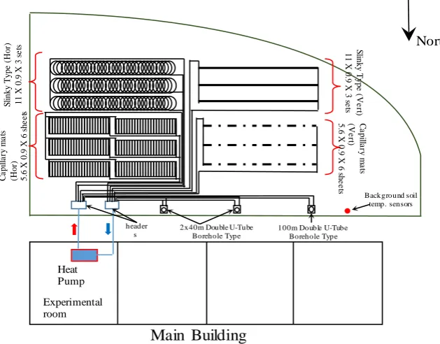
The experimental field was designed to have several heat exchangers for com-parative analysis, as illustrated in Figure 2. Vertical heat exchangers comprised of HDPE pipes, installed in two 40 m (double U-tube) boreholes and a 100 m (single U-tube) borehole. Horizontal (shallow) heat exchangers were slinky-coil HDPE pipes and capillary mat heat exchangers. Both types of horizontal heat exchangers were installed in two orientations, horizontal and vertical, at a depth of 1.4 m. However, only horizontally configured capillary mats and slinky heat exchangers are to be discussed in this paper.
Two trenches, each of which occupies 67.6 m2 (13 m × 5.2 m) area, were
ex-cavated for both slinky and capillary heat exchanger configurations. The trenches are wider than the total area required for both types. These extra spaces are de-signed to allow piping connection as well as proper spacing between heat ex-changers.
The installation of slinky heat exchanger involves pre-shaping HDPE pipe in-to the slinky configuration with necessary diameter and pitch size. This step, however, can be omitted for the case of capillary mat.
DOI: 10.4236/epe.2019.1111024 367 Energy and Power Engineering
[image:5.595.212.527.278.524.2]Figure 1.Annual soil temperature recorded at the test site, from April 1, 2018 to March 31, 2019.
Figure 2. Schematic showing the configuration of heat exchangers in the test field.
(a) (b)
Figure 3.Experimental room with the main GSHP system (a) and installation area of GHE’s (b).
30 60 90 120 150 180 210 240 270 300 330 360 Days in a year
0 4 8 12 16 20 24 28 32 Temperature ( O C) 0.1m 0.5m 1m 1.5m 10m
Main Building
Heat Pump2x40m Double U-Tube Borehole Type C a p illa ry ma ts (H or ) 5.6 X 0.9 X 6 s he e ts C a p illa ry ma ts (Ve rt) 5.6 X 0.9 X 6 s he e ts S li nky T ype ( H or ) 11 X 0.9 X 3 s e ts S linky T ype ( Ve rt) 11 X 0.9 X 3 s e ts
[image:5.595.212.541.560.690.2]DOI: 10.4236/epe.2019.1111024 368 Energy and Power Engineering
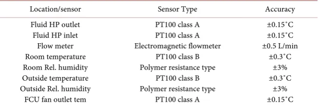
Table 1.List of sensors.
Location/sensor Sensor Type Accuracy Fluid HP outlet
Fluid HP inlet Flow meter Room temperature Room Rel. humidity Outside temperature Outside Rel. humidity
FCU fan outlet tem
PT100 class A PT100 class A Electromagnetic flowmeter
PT100 class B Polymer resistance type
PT100 class B Polymer resistance type
PT100 class A
±0.15˚C ±0.15˚C ±0.5 L/min
±0.3˚C ±3% ±0.3˚C
±3% ±0.15˚C
2.1. Capillary Mat Heat Exchangers
The capillary mat heat exchanger was made from polyethylene material having dimension of 5.6 m (in the flow direction) × 0.9 m × 0.0064 m. The exchanger comprised 117 small capillary tubes arranged in parallel, with each tube having an outer diameter 0.0064 m and inner diameter 0.0048 m. A single heat ex-changer is equivalent to a 655.2 m similar small capillary tube providing a heat exchange area of 13.178 m2 over an installation area of 5.04 m2. In total, the
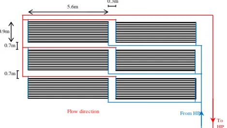
equivalent heat transfer area for six capillary mats is 79.07 m2. Figure 4 shows
the capillary mats being prepared for installation as ground heat exchanger. Six horizontal capillary mat heat exchangers were installed at a depth of 1.4 m in three rows and two columns, as shown in Figure 5. All mats were configured in parallel to the main pipeline. The main reason for adopting this configura-tion was that the pressure drop of a single mat is relatively high owing to the small-diameter capillary tubes. Considering the performance curve of the circula-tion pump given by the manufacturer, any series conneccircula-tion can result in a high pressure drop, exceeding the capacity of the pump.
2.2. Slinky Heat Exchangers
The HDPE pipe having inner outer diameter, d0 = 0.032 m and inner diameter,
di = 0.0254 m, were configured in 0.9 m diameter and 0.3 m pitch slinky loops configuration. With this configuration, a 120 m length HDPE pipe is converted into 11 m slinky. The slinky heat exchangers were installed in three parallels connections, each of which having an actual length of 120 m. The spacing be-tween slinky was set 0.6 m. Figure 6 shows the schematic arrangement of slinky heat exchanger. The total available heat transfer area is equivalent to 36.173 m2,
which is 54.25% less than those for capillary mat configuration.
3. Continuous Heating Test
DOI: 10.4236/epe.2019.1111024 369 Energy and Power Engineering mat, by 1˚C - 1.2˚C. The data shows that the soil temperatures during slinky test, at 1 m and 1.5 m depths were 6.6˚C and 8.5˚C, respectively, in contrast to 7.5˚C and 9.7˚C, respectively, for capillary mat configuration. Meanwhile, at the end of the test, the soil temperatures at 1 m and 1.5 m depths were 6.1˚C and 8.1˚C, for the case of slinky test and 7.2˚C and 9.1˚C for capillary mat. The temperature profile shown in Figure 1 also showed that the soil heat flux at the heat ex-changers depth was moving upward to the surface during the tests periods, as indicated by positive temperature gradient in upwards direction. It must be noted that the background soil temperatures were not measured in the ground heat exchanger location. Thus, it may not accurately represent the actual ground temperature at heat exchanger location. Nevertheless, the temperature variations in ground heat exchanger locations are likely to have similar variation with the background data. For both cases, the heating temperature setting was set to 21˚C, with 50% fan speed and fixed 45-degree nozzle position. Figure 8 shows the wind velocity, direct solar radiation, air pressure and relative humidity data during the tests. No rainfall was recorded throughout the test periods. To mi-nimize the heat loss from the experimental room, the central AC system and ven-tilation were turned off. Also, window’s blinds were closed as well as the activi-ties inside the experimental room were kept as minimum as possible throughout the test periods. Thus, the thermal load inside the building was only affected mainly by the outdoor temperature fluctuations.
[image:7.595.233.513.396.526.2](a) (b)
Figure 4. Capillary mat heat exchanger being prepared for installation (a) and its schematic description (b).
Figure 5. Schematic arrangement of the capillary mat heat exchangers. To HP
From HP
Flow direction 0.3m
0.7m
0.7m
5.6m
[image:7.595.255.490.572.704.2]DOI: 10.4236/epe.2019.1111024 370 Energy and Power Engineering
[image:8.595.250.499.232.356.2]Figure 6. Schematic arrangement of the slinky heat exchangers.
Figure 7. Outdoor temperature and ground temperatures at 1 m and 1.5 m depths, during experimental periods.
Figure 8.Outdoor temperature and ground temperatures at 1 m and 1.5 m depths, during experimental periods.
T o HP
From HP
Flow Direction 0.6m
0.6m
11m
1/15/19 1/19/19 1/23/19 1/27/19 1/31/19 2/4/19 2/8/19 2/12/19 Date
-4 0 4 8 12 16
Temperature(
0C)
Outdoor temp. (capillary) Ground Temp (capillary@1m)
Ground Temp ([email protected]) Outdoor temp. (slinky)
Ground temp (slinky@1m) Ground temp ([email protected])
0 20 40 60 80 100 120 140 160 180
Elapsed time (hours) 0
1 2 3 4 5 6
Wind Velocity (m/s)
0 0.2 0.4 0.6 0.8
Solar radiation (kWh/m
2)
1000 1008 1016 1024
Air pressure (hPa)
Capillary mat Slinky
0 20 40 60 80 100
[image:8.595.275.471.394.697.2]DOI: 10.4236/epe.2019.1111024 371 Energy and Power Engineering
4. Analysis and Discussion
4.1. Quantitative Analysis
The Coefficient of Performance (CoP), representing ratio of heat supplied into the room to the work required is calculated as:
CoP=QH WT (1)
here, Qh (in W) is the rate of heat supplied to the building and WT (in W) is the total electrical power consumption (see Figure 9), calculated as
T C F P
W =W +W +W (2)
where WC, WF, and WP are the electrical power for the compressor, fan, and cir-culation pump, respectively.
The data logger records the temperature and the both inlet and outlet GHE fluid temperatures as well as the flow-rate. Thus, Equation (1) is re-written as:
(
)
CoP= QG+WC WT (3)
where, QG is the heat extraction rate from the ground, calculated as
(
in out)
G m
Q = T −T ρcV (5)
Tout and Tin (in C) are, respectively, the GHE fluid temperatures at the heat-pump’s outlet and inlet, while ρ (kg/m3), c (J/kgC), and Vm (m3/s) are,
re-spectively, the density, specific heat capacity, and flowrate of the heat exchange fluid.
In order to quantify the variation of data during operational tests, standard deviation analysis is used
CoP=QH WT (5)
here, xi is the observed value, x is the average value, and N is the number of data points.
Assuming, the temperature difference between indoor and outdoor is the only source of thermal load, building thermal load can be calculated by:
(
indoor outdoor)
L
Q =hA T −T (6)
here, QL (Watt) is the thermal load, h(Wm−2K−1) is the overall heat transfer
coef-ficient of building’s wall, A (m2) is the area of heat transfer. As the current
DOI: 10.4236/epe.2019.1111024 372 Energy and Power Engineering
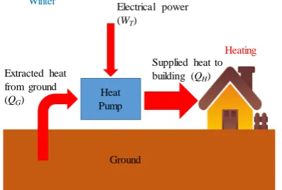
Figure 9.Schematic of energy flow during space heating using GSHP.
4.2. Temperatures and Ground Heat Extraction Rate
Figure 10 shows the heat pump’s inlet and outlet temperatures for both heat
ex-changers, as well as the flow-rate of heat exchangers fluid. The test using slinky heat exchangers indicated lower heat-pump operation temperature compared to the test using capillary mats. This indicated the lower ground temperature dur-ing the test usdur-ing slinky heat exchanger. The inlet and outlet temperature differ-ence are higher for the capillary mats heat exchanger. This is attributed to the lower flow-rate of heat exchange fluid.
Figure 11 shows the outdoor temperatures, room temperatures and Fan Coil
Unit (FCU) air temperatures during tests. The FCU air temperature was meas-ured at the fan outlet. It is important to note that despite the ground tempera-tures at heat exchanger’s depths, during the test using slinky heat exchanger are lower, the average outdoor temperatures indicate the opposite. Average outdoor temperature during slinky test is 3.04˚C (σ = 3.49) while for the capillary mats is 0.69 (σ = 2.14). The effect of higher outdoor temperature can be clearly seen at t
= 40 - 80 hours and t = 140 - 160 hours, where the FCU temperatures for slinky case are lower than those for capillary mats. Despite similar temperature setting were used for both configurations, the room temperature is slightly higher for the slinky configuration with average of 20.07˚C (σ = 0.48), in contrast to 19.34˚C (σ = 0.38), for the capillary mat. The higher standard deviation for slinky test can be explained as a result of higher thermal load fluctuations due to greater outdoor temperature variations. To compensate the thermal load fluctu-ation, the heat-pump system adjusts its operational parameter in two ways, the variable inverter control and/or ground circulation flow-rate. The data from
Figure 10 and Figure 11 suggest that heat-pump changes its heating load
pre-dominantly by adjusting the refrigerant compression ratio through variable in-verter control, rather than flow-rate. This can be seen from a relatively constant flow-rate throughout the test.
The total heat extraction and calculated CoP are shown in Figure 12. The calculated CoP for slinky and capillary mat are 2.81 (σ = 0.40) and 2.78 (σ = 0.28), respectively. The heat extraction rate and heat exchange fluid tempera-tures are showing consistent outcomes with the FCU temperatempera-tures. In addition,
Heat Pump Extracted heat
from ground (QG)
Electrical power (WT)
Supplied heat to building (QH)
Ground
Winter
DOI: 10.4236/epe.2019.1111024 373 Energy and Power Engineering the heat extraction rates were also decrease during these periods.
[image:11.595.266.484.249.506.2]4.3. Electricity Consumption and Coefficient of Performances
Figure 13 presents the electrical consumptions for both heat exchanger
[image:11.595.248.504.549.693.2]confi-gurations. The average electrical consumptions and the standard deviations for slinky and capillary mat, are respectively, 0.90 kW (σ = 0.16) and 0.96 kW (σ = 0.16). The total electricity consumptions are 149.67 kWh and 159.35 kWh, re-spectively. Slinky configuration consumed lower electrical energy due to lower heating load at t = 40 - 80 hours and t = 140 - 160 hours, which is consistent with the temperature and heat extraction rate, discussed in previous chapter (sub-chapter 4.2).
Figure 10. Heat-pump inlet and outlet temperatures and
volumetric flow-rate of ground heat exchanger fluid.
Figure 11. Outdoor temperatures, room temperatures and Fan Coil Unit
(FCU) air temperatures for both slinky and capillary mats heat exchangers.
0 20 40 60 80 100 120 140 160 180
Elapsed time (hours)
0 2 4 6 8 10
Temp
erature (
0C)
HP inlet (capillary mat) HP inlet (slinky)
HP outlet Temp. (capillary mat)
HP outlet Temp. (slinky) Flowrate (capillary mat) Flowrate (slinky) 0
4 8 12 16 20
Flow rate (Lt/min)
0 20 40 60 80 100 120 140 160 180
Elapsed time (hours) -10
0 10 20 30 40 50 60 70
Tempe
rature (
OC)
FCU outlet temp.
Room temp.
DOI: 10.4236/epe.2019.1111024 374 Energy and Power Engineering
Figure 12.Heat extraction rates and coefficient of performances.
Figure 13.Electricity consumption for both capillary mat and slinky heat exchanger.
4.4. Flow Rate of Heat Exchange Fluid
According to Figure 10, the average flow-rates for capillary mats and slinky heat exchangers are respectively, 10.88 Lt/min and 13.98 Lt/min. The experimental data with slinky heat exchanger shows larger fluctuations (σ = 0.85) in contrast to the capillary mat (σ = 0.53). Another important factor is the distance between the heat pump and the ground heat exchangers. The distance from the main header valves to the heat exchangers vary between, approximately 18 m to 45.5 m, depending on its position. The lateral distance between main header valve and the compressor unit inside the experimental room is 17 m. The series of bends and curves in pipeline also increase the effective hydraulic resistance. On the other hand, both flow-rates decline steadily, with slightly higher linear decline rate for slinky heat exchanger. The main reason is likely the higher hydraulic re-sistance of capillary mat. This is attributed to the small diameter of capillary tubes and abrupt contraction between capillary mat’s header and capillary tubes. Thus, higher hydraulic pressure is required to attain a given flow-rate.
0 20 40 60 80 100 120 140 160 180
Elapsed time (hours) 0
1 2 3 4
Heat extraction (kW)
1 2 3 4 5
CoP (-)
capillary slinky
0 0.5 1 1.5 2
Power Consumption (kW)
0 20 40 60 80 100 120 140 160 180
[image:12.595.259.492.330.454.2]DOI: 10.4236/epe.2019.1111024 375 Energy and Power Engineering
4.5. Thermal Load
[image:13.595.257.495.559.693.2]The calculated values of normalized thermal load for both cases are presented in
Figure 14. It can be clearly seen that the thermal load during test using capillary
mats is higher compared to the slinky heat exchangers, mainly as a result of different outdoor temperature during both tests. We found the average value
T(indoor)-T(outdoor) are 18.64˚C (σ = 2.15) and 17.07˚C (σ = 3.3) for capillary mat
and slinky, respectively. The higher value of standard deviation for slinky indi-cates more thermal load variations. For the duration of the entire tests, thermal load for capillary mat is 9.3% higher than those for slinky.
5. Conclusions
In this study, experimental tests have been carried out for a heat-pump coupled with two different ground heat exchangers, namely capillary mats and slinky type heat exchangers. Both tests were carried out continuously for 165 hours (~7 days). Both tests have been carried out in the periods where outdoor and ground temperatures were moderately different. During the test with slinky configura-tion, the average outdoor temperature was 3.04˚C, in contrast to 0.69˚C for the capillary mat. Similarly, the average thermal load during slinky test was lower than the capillary mat. Due to this condition, the thermal load during the test with capillary mat was found to be 9.3% higher than the test using slinky.
The background soil temperatures, located nearby the ground heat exchang-ers, also indicate temperature decrease during both tests. The ground tempera-tures at heat exchanger location are presumably higher during the test with ca-pillary mat, compared to slinky. This is primarily due to the test for caca-pillary mat was carried out earlier than the slinky.
Data analysis also indicated that for the given conditions, the slinky test con-sumed 149.67 kWh electrical energy, which is 6% lower than those for capillary mat, which is strongly affected by the thermal load. The flow-rate of heat ex-change fluid also suggests that the circulation pump works at high pressure, es-pecially during the test for capillary mat. In addition, the far distance between heat pump and ground heat exchangers as well as bends and curves along pipe-lines increase the effective hydraulic resistance.
Figure 14.Calculated heat load for the both experiments using capillary mats and slinky heat exchangers.
0 20 40 60 80 100 120 140 160 180
Elapsed time (hours) 0
4 8 12 16 20 24
Q
L
/
hA
(
0 C)
DOI: 10.4236/epe.2019.1111024 376 Energy and Power Engineering The overall results point toward the technical applicability of capillary mat as alternative to HDPE-based shallow heat exchanger.
6. Future Study
Despite present study provides insight on the possibility of using capillary mat as ground heat exchangers, as an alternative to the well-known slinky heat exchanger, there are some points that must be considered for further analysis. First, even though the tests were carried out in the same winter season, the time gap between two tests resulting in different ground temperatures. Second, the heat-pump thermal outputs, which correspond to the thermal loads, are only about 32% of heat-pump total heating capacity. Consequently, the heat extractions are also relatively low, which may not reflect the ideal capacity of ground heat exchang-ers. Third, the thermal loads were not equal throughout the entire tests due to the different outdoor temperatures. These considerations making an ideal com-parison for both heat exchanger configurations are impractical.
The future studies will consider Thermal Response Test (TRT), which enable the control of main test parameters, such as the heating rate and the flow-rate. This is expected to eliminate the second and third considerations mentioned above. On the other hand, numerical simulation plays an important role in analy-sis and design of shallow ground heat exchangers [26] [27] [28] [29]. The expe-rimental results can be used to validate the numerical model, from which, other parametric analyses can be done. This is expected for eliminating the first men-tioned consideration.
In addition, pressudrop tests are also required to quantify the hydraulic re-sistance of the capillary mat heat exchanger.
Acknowledgements
Authors would like to thank to Mr. Masayuki Tateno of Geo-system Co., Ltd for the information and discussion during experiments. This research is partially supported by the Leading Initiative for Excellent Young Researcher (LEADER), Ministry of Education, Culture, Sport, Science and Technology, Japan.
Conflicts of Interest
The authors declare no conflicts of interest regarding the publication of this pa-per.
References
[1] Sivasakthivel, T., Murugesan, K. and Sahoo, P.K. (2014) A Study on Energy and CO2 Saving Potential of Ground Source Heat Pump System in India. Renewable and Sus-tainable Energy Reviews, 32, 278-293.
https://doi.org/10.1016/j.rser.2014.01.031
DOI: 10.4236/epe.2019.1111024 377 Energy and Power Engineering
https://doi.org/10.1016/j.rser.2011.09.027
[3] Genchi, Y., Kikegawa, Y. and Inaba, A. (2002) CO2 Payback-Time Assessment of a Regional-Scale Heating and Cooling System Using a Ground Source Heat-Pump in a High Energy-Consumption Area in Tokyo. Applied Energy, 71, 147-160.
https://doi.org/10.1016/S0306-2619(02)00010-7
[4] Kikegawa, Y., Genchi, Y., Kondo, H. and Hanaki, K. (2006) Impacts of City-Block-Scale Countermeasures against Urban Heat-Island Phenomena upon a Building’s Ener-gy-Consumption for Air-Conditioning. Applied Energy, 83, 649-668.
https://doi.org/10.1016/j.apenergy.2005.06.001
[5] Kardinal Jusuf, S., Wong, N.H., Hagen, E., Anggoro, R. and Hong, Y. (2007) The In-fluence of Land Use on the Urban Heat Island in Singapore. Habitat International, 31, 232-242.https://doi.org/10.1016/j.habitatint.2007.02.006
[6] Arifwidodo, S. and Chandrasiri, O. (2015) Urban Heat Island and Household Energy Consumption in Bangkok, Thailand. Energy Procedia, 79, 189-194.
https://doi.org/10.1016/j.egypro.2015.11.461
[7] Garber, D., Choudhary, R. and Soga, K. (2013) Risk Based Lifetime Costs Assessment of a Ground Source Heat Pump (GSHP) System Design: Methodology and Case Study.
Building and Environment, 60, 66-80.
https://doi.org/10.1016/j.buildenv.2012.11.011
[8] Zhu, Y., Tao, Y. and Rayegan, R. (2012) A Comparison of Deterministic and Proba-bilistic Life Cycle Cost Analyses of Ground Source Heat Pump (GSHP) Applications in Hot and Humid Climate. Energy and Buildings, 55, 312-321.
https://doi.org/10.1016/j.enbuild.2012.08.039
[9] Sriamonkul, W., Intarajinda, R., Tongsuk, N. and Saengsuwan, S. (2011) Life Cycle Cost Analysis of Air Conditioning System for Residential Sector in Thailand. GMSARN International Journal, 5, 131-138.
[10] Park, N., Jung, S., Park, H., Choi, H., Chin, S. and Jung, H. (2010) Payback Period Estimation of Ground-Source and Air-Source Multi Heat Pumps in Korea Based on Yearly Running Cost Simulation.International Refrigeration and Air Conditioning Conference.
[11] Widiatmojo, A., Chokchai, S., Takashima, I., Uchida, Y., Yasukawa, K., Chotpantarat, S. and Charusiri, P. (2019) Ground-Source Heat Pumps with Horizontal Heat Ex-changers for Space Cooling in the Hot Tropical Climate of Thailand. Energies, 12, 1274.https://doi.org/10.3390/en12071274
[12] Mustafa Omer, A. (2008) Ground-Source Heat Pumps Systems and Applications.
Renewable and Sustainable Energy Reviews, 12, 344-371.
https://doi.org/10.1016/j.rser.2006.10.003
[13] Wu, R., Tinjum, J.M. and Likos, W.J. (2015) Coupled Thermal Conductivity Dryout Curve and Soil-Water Characteristic Curve in Modeling of Shallow Horizontal Geo-thermal Ground Loops. Geotechnical and Geological Engineering, 33, 193-205. https://doi.org/10.1007/s10706-014-9811-2
[14] Chalhoub, M., Bernier, M., Coquet, Y. and Philippe, M. (2017) A Simple Heat and Moisture Transfer Model to Predict Ground Temperature for Shallow Ground Heat Exchangers. Renewable Energy, 103, 295-307.
https://doi.org/10.1016/j.renene.2016.11.027
[15] Wu, Y., Gan, G., Verhoef, A., Vidale, P.L. and Gonzalez, R.G. (2010) Experimental Measurement and Numerical Simulation of Horizontal-Coupled Slinky Ground Source Heat Exchangers. Applied Thermal Engineering, 30, 2574-2583.
DOI: 10.4236/epe.2019.1111024 378 Energy and Power Engineering
[16] Xiong, Z., Fisher, D.E. and Spitler, J.D. (2015) Development and Validation of a Slin-kyTM Ground Heat Exchanger Model. Applied Energy, 141, 57-69.
https://doi.org/10.1016/j.apenergy.2014.11.058
[17] Zhou, G. and He, J. (2015) Thermal Performance of a Radiant Floor Heating System with Different Heat Storage Materials and Heating Pipes. Applied Energy, 138, 648-660.
https://doi.org/10.1016/j.apenergy.2014.10.058
[18] Xia, Y. and Zhang, X.S. (2016) Experimental Research on a Double-Layer Radiant Floor System with Phase Change Material under Heating Mode. Applied Thermal Engineering, 96, 600-606.https://doi.org/10.1016/j.applthermaleng.2015.11.133 [19] Hu, R. and Niu, J.L. (2012) A Review of the Application of Radiant Cooling & Heating
Systems in Mainland China. Energy and Buildings, 52, 11-19. https://doi.org/10.1016/j.enbuild.2012.05.030
[20] Carbonell, D., Battaglia, M., Philippen, D. and Haller, M.Y. (2018) Numerical and Experimental Evaluation of Ice Storages with Ice on Capillary Mat Heat Exchangers for Solar-Ice Systems. International Journal of Refrigeration, 88, 383-401.
https://doi.org/10.1016/j.ijrefrig.2018.02.007
[21] Zhao, M., Kang, W., Luo, X., Yu, C.W., Meng, X.Z. and Gu, Z. (2017) Performance Comparison of Capillary Mat Radiant and Floor Radiant Heating Systems Assisted by an Air Source Heat Pump in a Residential Building. Indoor and Built Environ-ment, 26, 1292-1304.https://doi.org/10.1177/1420326X16674517
[22] Echarri, V. (2017) Demand-Oriented Design Strategies for Low Environmental Im-pact Housing in the Tropics. Sustainability, 9, 1614.
https://doi.org/10.3390/su9091614
[23] Yafan, H., Chao, F., Yangyang, D., Xingqiao, J., Sukun, P. and Caijie, L. (2014) Build-ing Energy System Based on Capillary Mats. Electronic Journal of Geotechnical En-gineering, 19, 17627-17634.
[24] Promax-Engineering (2019) Horizontal Collectors.
https://promax-engineering.com/en/horizontal-collectors/
[25] Renewable Research Center (2019) SORA Weather Data.
https://www.renewable.pr.aist.go.jp/ent/en/past_frea_en
[26] Selamat, S., Miyara, A. and Kariya, K. (2016) Numerical Study of Horizontal Ground Heat Exchangers for Design Optimization. Renewable Energy, 95, 561-573.
https://doi.org/10.1016/j.renene.2016.04.042
[27] Esen, H., Inalli, M. and Esen, M. (2007) Numerical and Experimental Analysis of a Horizontal Ground-Coupled Heat Pump System. Building and Environment, 42, 1126-1134. https://doi.org/10.1016/j.buildenv.2005.11.027
[28] Li, C., Cleall, P.J., Mao, J. and Muñoz-Criollo, J.J. (2018) Numerical Simulation of Ground Source Heat Pump Systems Considering Unsaturated Soil Properties and Groundwater Flow. Applied Thermal Engineering, 139, 307-316.
https://doi.org/10.1016/j.applthermaleng.2018.04.142
[29] Gan, G. (2018) Dynamic Thermal Performance of Horizontal Ground Source Heat