Available Online at www.ijpret.com 404
INTERNATIONAL JOURNAL OF PURE AND
APPLIED RESEARCH IN ENGINEERING AND
TECHNOLOGY
A PATH FOR HORIZING YOUR INNOVATIVE WORK
ANALYSIS OF LIGHT WEIGHT SCISSOR DEPLOYABLE STRUCTURES WITH
DIFFERENT SPAN AND ANGLE OF SCISSOR-LIKE-ELEMENTS
PROF. DNYANESHWAR JADE 1. G. H. Raisoni College of Engineering and Management, Pune.
2. Department of Civil Engineering, S. P. university of Pune.
Accepted Date: 15/03/2016; Published Date: 01/05/2016
\
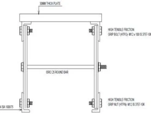
Abstract: Light weight Scissor Deployable Structure is a mechanism that is expanded from enclosing a small area or volume to enclose a large area or volume. The scissor deployable structure consists of two girdle beams having width 0.50 m and height are maintained by Scissor- Like-Elements flats size 100mm X 20 mm with angle 30°, 45° and 60°. The Scissor- Like-Elements flats and 4 Indian Standard Angle 100 mm X 75 mm X 10 mm is connected with High Tensile Friction Grip (HTFG) bolts to frame light weight Scissor Deployable Structure. The girdle beam cross Scissor- Like-Elements connected with ISRO 25. The light weight scissor deployable structure (bridge) is analyzed using STAAD.Pro V8i. In light weight scissor deployable structures 3 dimensional model of Scissor Bridge is developed that carries the moving load, that moving load is uniformly distributed over a bridge width 2.80 m, Span 7.0 m and 8.0 m. The analysis is carried out solely based on the static load expected. The result shows that Span 7.0 m and 8.0m Carries maximum load 42 KN and 35 KN respectively with angle of Scissor- Like-Elements 30° and optimum number of Scissor- Like-Elements are 16.
Keywords: Deployable Structures, Girdle Beam Element, Scissor- Like- Element (SLE), Flats Scissor- Like-Elements and Structural Optimization.
Corresponding Author: PROF. DNYANESHWAR JADE
Access Online On:
www.ijpret.com
How to Cite This Article:
Available Online at www.ijpret.com 405 INTRODUCTION
Deployable structures have their members connected in the factory, so that they satisfy a set of pre-assigned geometrical constraints. Erection is then operated by simply articulating the various components of the structure. Other advantages are the ease of transportation and storage, the minimum skill requirements for erection, dismantling and relocation, and the competitive overall cost. Bridge for use after earthquake and other emergency situations, temporary protective covers in remote construction sites or for curing of concrete in cold environments, domes for sport facilities, exhibition structures or shelters for travelling theatres. Deployable structures are of even greater interest in the aerospace industry, where severe constraints apply to both payload capacity of space ships and to building time in space.
Two types of deployable structures have been designed and constructed in the past.
(i) Structures that is stress-free in the folded configuration, during deployment, and in the
deployed configuration. Need to be stabilized by external locking devices An innovative geometric design methodology allows for structures that exhibit a stable and stress-free state in both the initial and the final configuration. However, geometric compatibility requirements cause the development of strains and stresses during the deployment procedure. The structural behavior of the structures during that phase is highly nonlinear; hence the analysis presents difficulties for the structural engineer.
(ii)Second order theory structural analysis of frames with analytical methods. However, an
Available Online at www.ijpret.com 406 Figure 1: Transitional Scissor Hinge Structures.
RESPONSE OF DEPLOYABLE SCISSOR BRIDGE STRUCTURES DURING DEPLOYMENT STAGE
The structural behaviour of deployable structures during deployment is of great interest due to its highly nonlinear nature. Therefore, both a qualitative understanding of the behavior and a quantitative evaluation of stresses occurring during deployment constitute an integral part of the design of deployable structures. The nature of the strains and stresses develop in the members of the structure during deployment defines the type of kinematic assumptions that have to be made for this problem. These strains and stresses result from compatibility requirements between the members of inner and outer SLEs. Furthermore, a small deformation has to take place before the structure can carry loads. The deployed configuration was used as initial state for the analysis, i.e. dismantling was simulated instead of deployment.
Nonlinear beam elements i.e. Girdle Beam have been used to model inner SLEs, while outer SLEs that are only subjected to axial stresses were represented by truss elements. After introducing auxiliary coordinate systems, the master node/slave node technique was used to model the pivotal connections.
PARAMETERS AFFECTING THE STRUCTURAL BEHAVIOR DURING DEPLOYAMENT STAGE
Available Online at www.ijpret.com 407
Parameters investigated here are the geometry of the Girdle Beam structure, the cross section of inner and outer SLEs, Properties of Angle section used in Girdle beam (ISA), Plate size and thickness, angle of SLE, and the length to stiffness ratio of the members.
Choosing a large cross-section of Angle section and Flats SLE in order to be on the safe side when loading the structure in the deployed configuration increases the stiffness of the structure and therefore the stresses that develop during deployment.
RESULT AND DISCUSSION
In deployable structures, Two Girdle Beam is spacing at 2.80 m c/c and Scissor Bridge having span 6.0 m, 7.0 m and 8.0 m over the Girdle beam a 30 mm thick plate are attached to a Beam element having 10 nodes for Finite Element Analysis. The overall Plate size is 6.0 m X 3.0 m X 30 mm, 7.0 m X 3.0 m X 30 mm and 8.0 m X 3.0 m X 30 mm.
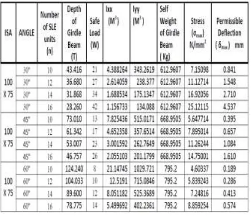
TABLE NO. 1: PERMISSIBLE DEFLECTION OF SCISSOR BRIDGE 7.0 M SPAN
Available Online at www.ijpret.com 408 TABLE NO. 2: PERMISSIBLE DEFLECTION OF SCISSOR BRIDGE 8.0 M SPAN
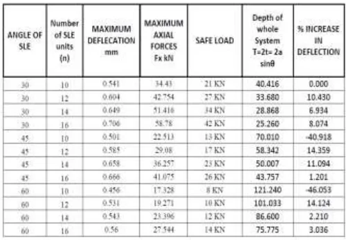
TABLE NO. 3: PERCENTAGE INCREASE IN DEFLECTION OF DIFFERENT INDIAN STANDARD ANGLE SECTION
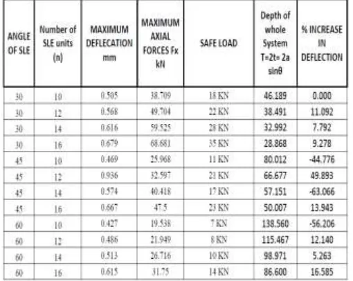
Available Online at www.ijpret.com 409 TABLE NO. 5: MAXIMUM SAFE LOAD 8.0 M SPAN ISA 100 X 75
CONCLUSION
As angle of Flat SLE increases from 30°, 45° and 60° the safe load carrying capacity decreases. In optimization of scissor deployable structures Maximum Nos. of SLE that result into maximum deflection. Optimize the structures with optimum Nos. of Flat SLE and minimum angle of SLE so that structures have minimum deflection and maximum load carrying capacity. Angle of Flat SLE 30° for span 6.0 m percentage increase in deflection up to 66% where as the span increases from 7.0 m to 9.0 m the percentage deflection within range from 16.2% to 13.6%. for angle of SLE as 45° the deflection is 15.4% and increases up to 56.2%. When compare Angle of Flat SLE 60° with 30° and 45° the percentage increase in deflection for span 6.0 m to 9.0 m are constant in range of 49.4% to 52.2%
REFERENCES
1. Gantes, C., Logcher, R. D., Connor, J. J., and Rosenfeld, Y. (1993). "Geometric design of
deployable structures with discrete joint size." Int. J. Space Struct., 8(2/3).
2. Torstenfelt, B. (1983). "Contact problems with friction in general purpose finite element
computer programs." Comp. Struct., 16(1-4), 487-493.
3. Hanus, J.P. “Investigation of a Deployable Military Bridge System with a Fiber Reinforced
Available Online at www.ijpret.com 410
4. Design of Structures with Seismic Isolation. Farzad Naeim, Ph.D., S.E. Vice President and
Director of Research and Development, John A. Martin and Associates, Inc., Los Angeles, California.
5. Minimum design loads for buildings and other structures, ASCE Standard ASCE/SEI 7-05,
American Society of Civil Engineers & ISBN 0-7844-0809.
a. Ario, m. Nakazawa, y. Yanaka, I. Tanikura, and S. Ono, Development of a prototype
deployable bridge based on origami skill., fuji, japan.
6. Bati, S.B., T. Rotunno and M. Tupputi. "Deployable Structures: A New Kind of Self-Locking
Mechanism." Conference Proceedings of IASS-APCS. Beijing, China, 2006.
7. M. Nakazawa and I. Ario, Mechanical Property of Deployable Emergency Bridge Based on the
Scissors Structures, Journal of safety problems, vol. 5 (2010) 133-138 (in Japanese).
8. Seismic Assessment of Concentrically Braced Steel Frames with Shape Memory Alloy Braces,
Jason McCormick, S.M.ASCE1; Reginald DesRoches, M.ASCE2; Davide Fugazza3; and Ferdinando Auricchio4.
9. Gantes, C., Logcher, R. D., Connor, J. J., and Rosenfeld, Y. (1990b). "Developing new concepts