
*Corr. Author’s Address: Chongqing University, The State Key Laboratory of Mechanical Transmission, 303 0 INTRODUCTION
The non-circular curved face gear drive is also called the orthogonal variable transmission ratio face gear drive. It is generated by replacing the spur pinion and its conjugated face gear of a conventional face gear drive by a non-circular gear and its conjugated
face gear [1]. The transmission ratio is variable
when the non-circular curved face gear engages with non-circular gear, since the teeth distributed on the cylindrical surface. This is the most significant feature compared to the conventional face gear. This type of gear drive has many possible applications in the field of engineering, textile, agriculture, etc.
In 1940, Buckingham came up with the concept
of the face gear in the paper [2], which he defined as
a rack of changing tooth pitch and pressure angles; Litvin and his team made a strong contribution to the research about face gears on the basis of their
predecessors’ research. His book [3] gave in-depth
research about the surface of the face gear in terms of the gear geometry and meshing principle; Ji et al and Zhu et al. did a lot of research on face gears in the field of tooth surface contact analysis, strength,
coincidence degree theory, etc. [4]; Lin et al. were
the first to propose a non-circular curved face gear and explored its tooth profile analysis, machining simulation, measurement, etc. and this study made significant achievements. To date there has been little
research about the tooth profile of non-circular curved face gears [5] and [6].
The error of the tooth profile will not only impact on the instantaneous transmission accuracy but also cause plastic deformation on the tooth surface of intermeshing gear. There exist some methods for using the numerical method to solve the gear tooth profile, for instance, Xia et al., Li et al. and Tong et al. calculated the tooth profile of a bevel gear using the numerical method which was based on the spherical coordinates [7] to [9]. In the field of gear measurement, Guenther et al. and Zhang et al. put forward some new theories and methods of measuring and analyzing gears [10] to [12]. But, at present, there is no practical way of using the numerical method to solve the tooth profile of non-circular curved face gear. This paper presents a new general numerical method used to calculate the tooth profile of a non-circular curved face gear. This method will serve as an important reference basis in the field of modeling, processing, analyzing errors of measurement, and so forth.
1 PARAMETERS OF THE CURVE IN THE CYLINDRICAL COORDINATE SYSTEM
The non-circular curved face gear is a kind of cylindrical gear. In order to describe and calculate the parameters of the gear more accurately, this paper prepared a study of the angle and the expansion of the curve under the cylindrical coordinate system.
Numerical Calculation of Tooth Profile
of a Non-circular Curved Face Gear
Lin, C. – Zeng, D. – Zhao, X. – Cao, X.
Chao Lin* – Dong Zeng – Xianglu Zhao – Xijun Cao
Chongqing University, The State Key Laboratory of Mechanical Transmission, China
Based on the cylindrical coordinates and the space engagement theory, which utilize a cylindrical coordinate system, an arbitrary curve equation was obtained and a method of curve expansion was established. This allows any order of pitch curve of non-circular curved face gear and normal equidistant curve parameter equations to be derived. The tooth profile points of the non-circular curved face gear can be solved using the numerical calculation method where the tooth profile intersects with the pitch curve and normal equidistant curves of non-circular curved face gear. Finally the numerical method used to solve the tooth profile of the non-circular curved face gear was proved to be accurate and correct from the small error between measured data and the data of theoretical calculation.
Keywords: non-circular curved face gear, cylindrical coordinates, pitch curve, numerical calculation of tooth profile, error analysis
Highlights
• Built a mathematical model and a expansion method of an arbitrary curve.
• Derived equations of the pitch curve and the normal equidistant curves of the non-circular curved face gear. • Proposed a numerical method to calculate the tooth profile.
2
θ
1
θ
M
N
Γ
O
1
γ
2
γ
'
M N'
X
Y Z
K
1
h
2
h
β
Fig. 1. Parameters of the curve in the cylindrical coordinate system
As shown in Fig. 1, O – XYZ is the cylindrical
coordinate system, Γ is one curve on the cylindrical surface, M and N are any two points on the curve. θ is the rotation angle which is from the positive X axis to
the point. h is the distance between the point and the
bottom surface, γ is the central angle of the point on
the curve, R is the cylindrical radius.
1.1 Basic Description of the Curve
Assume that the equation of any curve is:
Γ =
(
Rcosθ Rsinθ h( )
θ)
. (1) The arc length between points M and N is:LMN =
∫
R +h( )
d2 2 1
2 '
, θ θ
θ θ
(2)
where h'(θ) is the derivative of h(θ).
The central angle of one point on the curve can be defined as the angle between the line which links that point to the center of the circle in the bottom surface and the bottom surface. According to the geometric relationship the formula is:
γ =arctanh
( )
θ .R (3)
1.2 Expansion of the Curve
The line linking all points on the curve to the center of the circle in the bottom surface will compose a conical surface. As shown in Fig. 1, there are countless
tangent planes through point N. However, there exists
a unique tangent plane that is vertical to the Z axis.
There exists one point K on the line intersected by
the tangent plane and the cylindrical surface where
LMN =LNK. At the same time the plane OKN is an
expansion of the plane OMN. To solve Eq. (2), we get:
LNK =LMN =
∫
R +h( )
d2 2 1
2 '
. θ θ
θ θ
(4)
Thus the expansion angle β corresponding to the
curve MN is:
β
θ θ θ θ
θ
=
+
( )
∫
+( )
12 2
2 2 1
2
R h R h d
'
. (5)
2 PITCH CURVE OF THE NON-CIRCULAR CURVED FACE GEAR
2.1 Equation of the Pitch Curve
According to the meshing relationship of the non-circular curved face gear pair, a coordinate system can be established.
1 O
1 X
1 Y
1 Z E
Ι
R O2
2 X
2 Y 2
Z
( )
1 r ξ1
ξ
2
ξ h
( )
ξ2 1P P2
Fig. 2. Meshing coordinate of the non-circular curved face gear
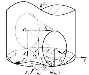
As shown in Fig. 2, the axis of the non-circular gear is orthogonal to axis of the non-circular curved face gear. As shown in Fig. 2, O1 – X1Y1Z1 is the
fixed coordinate system of the non-circular gear. O2 – X2Y2Z2 is the fixed coordinate system of the
non-circular curved face gear. The point P1 is on the pitch
curve of non-circular gear and the point P2 is on the
pitch curve of non-circular curved face gear. When
P1 coincides with P2, the non-circular gear turns at
an angle of ξ1 , and the non-circular curved face gear
turns at an angle of ξ2 . The radius of the pitch curve
of the non-circular curved face gear is R, and the
radius vector of the non-circular gear is r(ξ1) . Under
the face gear is E. I is the pitch curve of non-circular curved face gear.
According to the theory of non-circular gears, the equation for the pitch curve of the non-circular gear is:
r a e
e n
ξ
ξ
1
2
1 1 1
1
( )
=(
−)
− cos(
)
, (6)
where, ξ1 is the polar angle of the elliptic gear, a is half
of the longer axis of the ellipse, e is the eccentricity of the ellipse, n1 is the order of the non-circular gear.
When the parameters in Eq. (6) were chosen as
follows: a = 35 mm, e = 0.1 and n1 changes from 1
to 4. The pitch curve of the non-circular gear can be shown in Fig. 3.
30
210
60
240 90
270 120
300 150
330
180 0
30
210 240
90
270 120
300 150
330
180 0
60
30
210 240
90
270 120
300 150
330
180 0
60
30
210
60
240 90
270 120
300 150
330
180 0
Fig. 3. Impact of n1on the pitch curve of the non-circular gear
In the meshing process of the non-circular gear and non-circular curved face gear, the center distance is fixed. From the geometric relationship shown in Fig. 2, Eq. (7) is correct at any point in time.
E h=
( )
ξ2 +r( )
ξ1 = +a ae, (7)where, h(ξ2) is the distance between the point on the
pitch curve and the bottom surface when the non-circular face gear turns an angle ξ2.
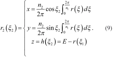
By substituting Eq. (6) and Eq. (7) into Eq. (1), the pitch curve of the non-circular curved face gear can be obtained.
r
x R y R
z h E r
2
2
2
2 1
=
= =
=
( )
= −( )
cos
sin
ξ ξ
ξ ξ
, (8)
where,
R n= 2
∫
n r( )
d0 2
2
1
π ξ ξ
π
, ξ ξ ξ ξ ξ ξ
2
12
0 0
1 1
1 1
=
∫
=∫
( )
i d R r d ,
n1 is the order of the non-circular gear, n2 is the order
of non-circular curved face gear, i12 is the transmission
ratio of the non-circular curved face gear pair and i12=
R / r(ξ1).
By substituting the equations above into Eq. (8), the pitch curve of the non-circular curved face gear can be obtained.
r
x n r d
y n r d
z h
n
n
2 2
2 2
0 2
2
2 0 2
2 2
2
1
1 ξ
π ξ ξ ξ
π ξ ξ ξ
ξ
π
π
( )
==
( )
=
( )
=
∫
∫
cossin
(( )
= −( )
E r ξ1
. (9)
2.2 Tooth Modulus Angle of the Pitch Curve Plane
As shown in Fig. 4, based on the method of the expansion of the curve, tooth 1 and tooth 2 represent any 2 teeth on the pitch curve of the non-circular
curved face gear. Point M and point N are the points
on the right tooth profile of tooth 1 and tooth 2. There
is a complete tooth profile between M and N. By
expanding the tooth profile on the tangential circle of the pitch curve, the point K on the tangential circle can
be obtained. When the arc length of MN is equal to
KN, the plane OKN is the expansion plane of the one
tooth profile.
O R
m
πβ
1 M N 2
K
X
Y Z
1
θ
2
θ
Pitch curve Tangential
circle
Fig. 4. Tooth modulus angle of the non-circular curved face gear
When the angle β = πβm , βm is the modulus angle
2.3 Addendum Angle and Dedendum Angle
As shown in Fig. 5, the addendum line, pitch curve and dedendum line of the non-circular curved face gear are on the cylindrical surface Π. The tangential
plane through the center point O of the bottom
surface intersects with the addendum line, pitch curve
and dedendum line at points M, P and N. MN is the
tangent section on the cylindrical surface. Angles
MOP and PON are defined as the addendum angle and
the dedendum angle. And,
α β
α β
a a m
f a m
h h c
= ⋅ =
(
+)
∗
∗ ∗ , (10)
where, ha∗ is the addendum coefficient, c* is the
dedendum coefficient. βm is the modulus angle.
So the addendum and dedendum of the non-circular curved face gear are:
h R h
h R h
a a
f f
=
(
+)
⋅( )
=(
−)
⋅( )
tan
tan
,
γ α ξ
γ α ξ
2 2
(11)
where, γ is the center angle, R is the radius of the
pitch curve of non-circular curved face gear, αa is the
addendum angle of non-circular curved face gear, and
αf is the dedendum angle of non-circular curved face
gear.
O
X
Y
Z Π
1
2 3
M P N
R
a α
f α
Fig. 5. Addendum angle and dedendum angle (1 addendum line, 2 pitch curve, and 3 dedendum line)
3 USING THE NUMERICAL METHOD TO SOLVE TOOTH PROFILE
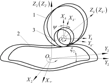
The fundamental theory of the numerical method in solving the tooth profile of non-circular curved face gear is derived from the generating process of the non-circular curved face gear. The generating process is shown in Fig. 6.
2 O
2
X X2'
2' Y
2 Y 2
ξ
k
X Xk' Z Zk
( )
k'( )
2 2' Z Z
k
O Yk
'
k
Y ψ
1
2 3
Fig. 6. Coordinate system of generating process
As shown in Fig. 6, Ok – Xk Yk Zk is rigidly
connected to the frame of the cutting machine. Ok' – Xk' Yk' Zk' is rigidly connected to the cutter.
Likewise O2 – X2Y2Z2 is rigidly connected to the
frame of the cutting machine. O2' – X2' Y2' Z2' is rigidly
connected to the non-circular curved face gear. According to the principle of gear engagement, the transformation matrix from Xkk' to M2'2 can be
derived as:
M M M M
R
k k kk
2 2 2 2
2 2 2 2
2
' ' ' '
sin sin cos sin cos cos
sin cos
= =
=
−
ψ ξ ψ ξ ξ ξ
ψ ξ ccos cos sin sin
cos sin
,
ψ ξ ξ ξ
ψ ψ ξ
2 2 2
2
0
0 0 0 1
−
−
( )
R
h (12)
where, ψ is the rotating angle of cutter when the
non-circular curved face gear rotates at an angle of ξ2 .
The rotation angle of the cutter can be obtained from the processing geometric relationships.
ψ π ξ ξ
ξ
ξ ξ ξ
ξ
= − −
( )
( )
+
+
∫
( )
+( )
2 1
1
1
2 2
0
1
arctan '
'
,
r r
r r d
rk
(13)
where r'(ξ) is the derivative of r(ξ) and rk is the radius
of the pitch curve of cutter gear.
3.1 Equation of the Equidistant Curve of the Pitch Curve
The equation of the normal equidistant curve can be derived from the pitch curve equation of the non-circular curved face gear.
In Fig. 7, curves 1, 2, 3 stand for the expansion of addendum line, pitch curve and dedendum line of a non-circular curved face gear, respectively. Pa is the
of the pitch curve through point P. Pf is the intersection
of the dedendum line and the normal line of the pitch curve through point P. η is the angle of the normal and vertical direction and therefore η can be expressed as:
η ξ
ξ
=
(
)
−
(
)
arctan
sin
cos .
en n
en n
1 1 1
1 1 1
1 (14)
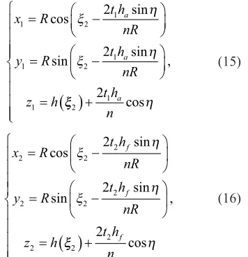
Assuming that there are n normal equidistant
curves between the addendum line and the dedendum
line. The parametric equations of n / 2 equidistant
curves from the pitch curve to the addendum line and
another n / 2 equidistant curves from the dedendum
line to the pitch curve can be derived from Eq. (9).
x R t h
nR
y R t h
nR z h
a
a
1 2
1
1 2
1
1
2
2
= −
= −
=
cos sin
sin sin
ξ η
ξ η
ξξ2 η
1 2
( )
+
t h na cos
, (15)
x R t h
nR
y R t h
nR
z h
f
f
2 2
2
2 2
2
2
2
2
= −
= −
=
cos
sin
sin
sin
ξ η
ξ η
ξξ2 η
2 2
( )
+
t h n
f cos
, (16)
where, n is the number of the normal equidistant
curves. The t1 and t2 represent respectively the t1 – th
equidistant curve from the pitch curve to addendum line and the t2 – th equidistant curve from the pitch
curve to dedendum line respectively. When t1 = n / 2,
it is the addendum line. When t2 = n / 2, it is the
dedendum line.
O Z
Y
1 2
3 η Pa
P
f
P
a
h
f
h
Fig. 7. Planimetric pitch curve of non-circular curved face gear
3.2 Using the Numerical Method to Solve the Tooth Profile
The tooth profile of the non-circular curved face gear can be derived by building the equation of the normal equidistant curve of the non-circular curved face gear using the method above. During the process, the intersection is at a given point if it satisfies the engagement conditions when the cylindrical cutter tooth profile associates with the equidistant curve of the pitch curve of the non-circular curved face gear.
According to mechanical principles, the tooth profile equation of an involute cylindrical gear cutter is [13]:
x r
y r
k b ko k k ko k k b ko k k
= ±
(
+)
−(
+)
= −(
+)
+sin cos
cos sin
θ θ θ θ θ θ θ θ θθko θk
k k
z u
+
(
)
=
, (17)
where ± stands for left or right tooth profile of the cutter gear. rb is the radius of the base circle, θk is the
angle of any point on the involute, θko is the angle
from the involute-starting point to the center line of the gullet, θko = π / 2z+invαk , uk is the parameter in the
direction of tooth width and αk is the pressure angle of
the cutter gear.
When uk is determined, the tooth profile of
the cutter gear can be calculated by the software of Matlab. According to the coordinate transformation equation P2' = M2'k' Pk' , the tooth profile of the cutter
gear is transferred to the following coordinates of the non-circular curved face gear. Thus, the intersections are calculated through the equations of the line of the points obtained above and the equidistant curve equation of the pitch curve of the non-circular curved face gear.
As shown in Fig. 8a, the left tooth profile of the cutter has four points, which equidistant from one
another. P P P P1
2 2
2 3
2 4
2
', ', ', ' are obtained by transforming
the points to the coordinates O2' – X2' Y2' Z2' . Three
lines can be obtained by linking the adjacent points. Intersections are calculated though the equations of the lines and equidistant curves.
equation. So the intersection points obtained above
should satisfy the meshing equation [1]:
N v
r r r r r
i R u
k
b k k
k
⋅ =
= +
(
−)
( )
+ −( )
− −(
+)
2
2 1
2
1
21
2
cos sin
co
ζ λ ξ ξ µ
s
sζ =0, (18)
where N stands for the normal line of cutter tooth
surface and v2kstands for the relative velocity of the
cutter and the non-circular curved face gear. These two parameters need to be expressed in the same coordinate system. As shown in Fig. 8b rb = rk cos αk
and ζ = ψ + ξ1 – θk – θko .
Finally the points that satisfy Eq. (18) are on the tooth profile.
a)
2' 2 P
1' 1 P
3' 3 P
4' 4 P
Pitch curve
Tooth profile of cutter
Normal equidistant
curve
b)
1
O Ok1
2
k
O
1 X 1
Y µ
1
k
X 1
k
Y 2
k
Y
2
k
X 1 ξ λ
2π σ−
1 P '
1 P
2 P
ψ
Tangent line
Pitch curve of
non-circular gear Pitch curve of cutter
Fig. 8. Numerical method for solving the tooth profile; a) intersection of the tooth profile and normal equidistant curves
and b) space location of the gear shaper cutter
3.3 Examples of Calculation
The 4-order non-circular curved face gear is processed using an involute cylindrical gear cutter where the
parameters are the tooth number z = 12, the pressure
angle αk = 20° , and the module m = 4. The gear pair is
shown in Fig. 9.
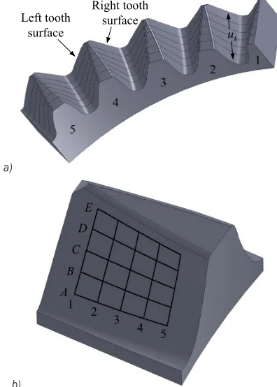
As shown in Fig. 10a, according to the principle of using the numerical method to solve the tooth profile [10] to [12], the uk is divided in accordance with
a tooth width of 72.5 mm, 74.5 mm, 76.5 mm, 78.5 mm, 80.5 mm. 5 equidistant curves used to divide the tooth are distributed 1.5 mm from one another along the tooth depth direction. The middle one of the 5 curves is coincide with the pitch curve.
Non-circular curved face gear Non-circular gear
Fig. 9. Material object of non-circular curved face gear
Here we calculate the coordinate value of the left tooth surface of tooth 1. The results of the mesh generation are shown in Fig. 10b. The coordinate values are shown in Table 1.
a)
k
u
Left tooth surface
Right tooth surface
b) A
B C
D E
1
2 3 4 5
Table 1. Coordinate values of theoretical points on the left surface of tooth 1 in [mm]
1 3 5
E
-80.49168, -1.13698,
3
-76.48175, -1.66847,
3
-72.46920, -2.11100,
3
C -80.43873,-3.14385, 0
-76.43156, -3.23707,
0
-72.42771, -3.23691,
0
A
-80.32150, -5.35782,
-3
-76.32929, -5.10585,
-3
-72.34882,
-4.67954,-3
3.4 Measurement of Non-Circular Curved Surface Gears
As shown in Fig. 11, the non-circular curved face gear was measured by the contour scanning software of a German Klingelnberg P26 automatic CNC controlled gear measuring center. Since each tooth profile in one cycle on the gear is different, contour scanning should be used as the measuring.
Fig. 11. Profile measurement of the non-circular curved face gear
Table 2. Coordinate values of the measured points on the left surface of tooth 1 in [mm]
1 3 5
E -80.477,-1.138, 3
-76.484, -1.661,
3
-72.459, -2.105,
3
C
-80.441, -3.132,
0
-76.434, -3.224,
0
-72.419, -3.227,
0
A -80.323,-5.369, -3
-76.323, -5.106,
-3
-72.349, -4.667,
-3
According to the measurement and theoretical calculation process, the radius of tooth width, which is the motion trajectory of the probe, is the same as the one calculated above. The coordinate values of the grid nodes on the left tooth surface of tooth 1
are obtained using the measurement points from the neighboring space of the theoretical point from the measured data. The specific values are shown in Table 2.
3.5 Error Analysis of the Tooth Profile
Since there are errors in the actual processing, measurement and in the precision of the numerical method, there also exist errors between the measured values and the theoretical values.
Assuming that the normal distance between the measured point and the theoretical point is the normal
error Δd, which is used to measure the deviation
between two points. According to the following equation [3]:
∆d=
(
R*m−Rm)
⋅nm, (19)where Rm* is the coordinate value of the measured
points, Rm is the coordinate value of the theoretical
points and nm is the normal direction of the tooth
surface.
The deviation values are obtained by calculating for a real example. The results are shown in the Fig. 12.
Inner of the tooth Units in
14.7
12.1
11.3
6.3 7.8
5.6
11.8
13.2
12.5 1
2 [µm]
15.8
15.7 4.9
5.6
5.7
5.3 4.7
8.6
5.5 12.5
15.7 11.9 12.8 13.5
11.5
11.4
Theoretical value Measured value
Fig. 12. Error distribution (1 measured value grid, and 2 theoretical value grid)
4 CONCLUSION
In the article, a new kind of gear was generated and geometric and mathematical models were established for this gear. A numerical method used to calculate the tooth profile of the non-circular curved face gear was developed. The correctness of the method was examined by an experiment. The results of the performed research allow the following conclusions to be drawn:
a) The relevant parameters of arbitrary curves were calculated in terms of the cylindrical coordinate system. The parametric equations of the pitch curve of the non-circular curved face gear and the normal equidistant curve equation were obtained.
b) The tooth profile of the non-circular curved face gear in the tooth width direction was obtained by changing the point on the tooth profile of the cutter to the coordinate system of the non-circular curved face gear through the method of coordinate conversion and where the intersection with its pitch curve and the normal equidistant curve occurs.
c) The error of the tooth profile between the theoretical calculations and the actual measurements was analyzed. The results showed that using the numerical method to solve the tooth profile of a non-circular curved face gear high precision and good universality. This calculation method will be of service in the field of error analysis of the tooth surface, accuracy assessment of tooth surface and manufacture, and so on.
5 ACKNOWLEDGEMENTS
The authors would like to recognize the support of the National Natural Science Foundation of China (51275537) for this research.
6 REFERENCES
[1] Hai, G. (2012). Transmission Design and Characteristic
Analysis of Orthogonal Non-circular Face Gear Drive. MSc Thesis, Chongqing University, Chongqing, p. 7-24. (in Chinese)
[2] Buckingham, E. (1988). Analytical Mechanics of Gears. Dover
Publication, New York, p. 6-32.
[3] Litvin, F.L. Faydor, L. (2004). Gear Geometry and Applied
Theory. Cambridge University Press, New York, p. 484-518, DOI:10.1017/CBO9780511547126.
[4] Guanghu, J., Rupeng, Z., Heyun, B. (2010). Nonlinear
Dynamical Characteristics of Face Gear Transmission System.
Journal of Central South University (Science and Technology), vol. 41, no. 5, p. 1807-1813. (in Chinese)
[5] Chao, L., Shasha, L., Hai, G. (2014). Design and 3D modeling
of orthogonal variable transmission ratio face gear. Journal of
Hunan University (Natural Sciences), vol. 41, no. 3, p. 49-55, DOI:10.3969/j.issn.1674-2974.2014.03.009. (in Chinese) [6] Chao, L., Hai, G., Ning, N., Qinlong, Z., Lei, Z. (2013). Geometry
design, three-dimensional modeling and kinematic analysis of
orthogonal fluctuating gear ratio face gear drive. Proceedings
of the Institution of Mechanical Engineers, vol. 227, no. 4, p.
779-793, DOI:10.1177/0954406212453382.
[7] Jiqiang, X., Yuanyuan, L., Chunming, G., Jiangbin, S. (2008).
Noncircular bevel gear transmission with intersecting axes.
Journal of Mechanical Design, vol. 130, no. 5, p. 054502, DOI:10.1115/1.2885510.
[8] Jiangang, L., Xutang, W., Shimin, M., Jingliang, H. (2005).
Numerical computation of tooth profile of noncircular gear.
Journal of Xi‘an Jiaotong University, vol. 39, no. 1, p. 75-78. DOI:10.3321/j.issn:0253-987X.2005.01.018. (in Chinese) [9] Ting, T., Fangyan, Z., Ke, S., Bing, Y. (2013). Non-circular gear
teeth profile numeric method based on normal tooth profile.
Journal of Wuhan University of Technology (Transportation Science & Engineering), vol. 37, no. 3, p. 652-654, DOI:10.3963/j.issn.2095-3844.2013.03.048. (in Chinese) [10] Guenther, A., Kniel, K., Härtig, F., Lindner, I. (2013).
Introduction of a new bevel gear measurement standard, CIRP
Annals - Manufacturing Technology, vol. 62, no. 1, p. 515-518, DOI:10.1016/j.cirp.2013.03.083.
[11] Guenther, A. (2011). Interpretation of bevel gear topography
measurements. CIRP Annals - Manufacturing Technology, vol.
60, no. 1, p. 551-554, DOI:10.1016/j.cirp.2011.03.060.
[12] Jinliang, Z., Zongde, F., Xuemei, C., Xiaozhong, D. (2007). The modified pitch cone design of the hypoid gear: manufacture,
stress analysis and experimental tests. Mechanism and
Machine Theory, vol. 42, no. 2, p. 147-158, DOI:10.1016/j. mechmachtheory.2006.09.008.
![Table 2. Coordinate values of the measured points on the left surface of tooth 1 in [mm]](https://thumb-us.123doks.com/thumbv2/123dok_us/8950016.1859384/7.598.329.525.416.569/table-coordinate-values-measured-points-left-surface-tooth.webp)
