180 Copyright © 2011-15. Vandana Publications. All Rights Reserved.
Volume-5, Issue-1, February-2015
International Journal of Engineering and Management Research
Page Number: 180-184
GroCE: A Gross Climatic Effect Thermal Model for Three Phase
Induction Motor
Banti Khan1, Ashita Goyal2
1
School of Energy and Environmental Studies, DAVV, Indore, INDIA
2
School of Computer Science and IT, DAVV, Indore, INDIA
ABSTRACT
This paper presents a thermal circuit model to predict the behaviour of a three phase cage rotor induction motor during steady state operation under rated load. The proposed model GroCE (Gross Climatic Effect) allows the calculation of temperature distribution and thermal heat source parameters of motor including temperature variations due to different climatic conditions. A twelve months experimental study was conducted in variable climates of Indore City (India), on a 1.1 kW three phase Totally Enclosed Fan Cooled (TEFC) Induction motor. On the basis of study GroCE thermal model is developed which is helpful to design more efficient electric motorized system.
Keyword-- Climatic conditions, Heat source parameters, TEFC induction motor, Temperature distribution, Thermal circuit model.
I.
INTRODUCTION
Three phase induction motors consume approximately 60% of industrial electricity. Just 1% increase in efficiency of all the motors in India will save approximately 500MW power [1]. Three phase induction motors are widely used in heavy and medium industrial load application and agriculture purposes supplied to the industrial load is consumed by induction motorized system. It is therefore important to improve the efficiency of this type of electric motorized system [2]. The efficiency of induction motor is mainly depends on the properties of enamel used for coating of the windings of motor and the thermal withstanding capacity of the insulation used in motors. Thus the efficiency and performance of motor has very strong relationship with its operating and surrounding temperature [3]. For the purpose of rise in sufficiency and improving thermal withstanding capacity, an effective thermal model is required to predict the overall temperature rise in Totally Enclosed Fan Cooled (TEFC) motors.
The prediction of temperature distribution inside and operating electric motor is one of the most important tissues during its design. This prediction is the
key factor for the machine designer to evaluate the thermal class of motor, establishing the bearing lubrication intervals as well as maintaining the supplied air flow of the cooling system for ensuring the sufficient normal motor operation at rated conditions. Recognising the importance of the thermal factor in the overall effectiveness of motor design, different techniques have been proposed for thermal monitoring in practical those related to rotor and stator temperature [4].
Several works have been done for the induction motor based on thermal circuit modelling as in [5], [6] and [7]. These works allow predicting the motor’s temperature variation and distribution can be used for determining the effect of different designs, duties and cooling mechanisms during its operation but still there is no model which describes overall effect of temperature variations due to climatic changes, weather impact of different location on the performance of induction motor. In this paper, a mathematical Gross Climatic Effect (GroCE) model is developed which is based on the overall effect of temperature variation on motor due to climatic and seasonal changes. Tgce (Gross Climatic
Effect Temperature) is formulated on the basis of the study conducted during the period of 12 months (1 January 2014 to 31 December 2014) at the location of Indore city (India).
GroCE model allowing one calculate the distribution of motor temperature accurately with the specific ambient temperature as a function of input parameters determined by the operating conditions. This paper is divided in two sections, in section II formulation of Gross Climatic Effect Temperature Tgce is derived
181 Copyright © 2011-15. Vandana Publications. All Rights Reserved.
II.
FORMULATION OF GROSS
CLIMATIC EFFECT TEMPERATURE
T
gceFOR INDUCTION MOTOR.
An electric machine is a complex engineering system that consists of different materials with different thermal properties and distributed heat sources. A good knowledge of internal thermal condition of motor is very important for proper utilization of the motor, for optimum de-rating of the motor and to save the motor from burn out [8][9]. The performance of induction motor mainly effected due to the inside and outside temperature. Various thermal modelling have been done on the inside temperature behaviour of motor [10] but still no model is developed which shows a strong relationship between variation in temperature of surroundings due to climatic change (seasonal effect) and motor’s thermal performances.
In earlier thermal model calculations surrounding temperature is taken by default as ambient temperature and after this there is no significance of the climatic condition of that particular location and its temperature effect on motor is taken into calculation. In this paper a study was conducted on a 1.1kW three phase industrial induction motor, which is operated approximately 8 hour in day. Study was done at Indore, India from the period 1 Jan 2014 to 31 Dec 2014 (1 year period) and motors surrounding temperature was noted which is shown in table 1. On the basis of study a simple relation is developed as
𝑇𝑇𝑔𝑔𝑔𝑔𝑔𝑔 =𝑇𝑇𝑎𝑎𝑎𝑎𝑎𝑎 ±𝑇𝑇𝑣𝑣𝑎𝑎𝑣𝑣𝑣𝑣𝑎𝑎𝑎𝑎𝑣𝑣𝑔𝑔
Tgce is the gross climatic effect temperature which is the
combined effect of the previously adopted ambient temperature Tamb and variable temperature Tvariable
Month
due to climatic changes.
Table. 1 Temperature variation of motor surrounding (2014).
Max. Temp. In
0
Avg. Temp. In
C 0
Minimum Temp. In C 0C
Jan 26.5 18.2 9.8 Feb 28.8 20.2 11.4 Mar 34.3 25.3 16.2 Apr 38.7 30 21.1 May 40.4 32.4 24.4 Jun 36.2 30.1 24.1 Jul 30.3 26.5 22.6 Aug 28.2 25.1 21.9 Sep 30.9 26 21.1 Oct 32.4 25.3 18.1 Nov 29.7 21.8 13.9 Dec 26.9 18.8 10.6
III.
GROCE MODEL FOR THERMAL
ANALYSIS OF THREE PHASE
INDUCTION MOTOR
GroCE model is based on following energy balance equation:
𝜌𝜌 �𝜕𝜕𝑔𝑔𝜕𝜕𝜕𝜕+𝑔𝑔∇𝑣𝑣�=𝜎𝜎 − ∇𝑞𝑞+𝑔𝑔𝑒𝑒 (1)
𝜌𝜌 is the density of material, e is the internal energy, q is the energy flux, 𝜎𝜎 is deformation and stress tensor and Q is the energy supply. This equation can be reduced to the following form [11]:
𝜌𝜌𝜕𝜕𝑔𝑔𝜕𝜕𝜕𝜕+∇.𝑞𝑞=𝑒𝑒� (2)
Where𝑒𝑒�=𝜌𝜌𝑒𝑒+𝜎𝜎𝑇𝑇 accounts for the energy supply and change in different types of losses. Example: friction and cooling losses, electromagnetic losses. Assuming that the internal energy can be expressed as 𝑔𝑔=𝑔𝑔(𝑣𝑣) then
𝑑𝑑𝑔𝑔
𝑑𝑑𝜕𝜕 =𝐶𝐶𝑣𝑣
𝑑𝑑𝑑𝑑
𝑑𝑑𝜕𝜕 (3) Where
𝐶𝐶𝑣𝑣=𝑑𝑑𝑔𝑔𝑑𝑑𝑑𝑑 is the specific heat at constant volume. Equation
(1)-(3) is based on boundary and initial conditions depending on the part of the motor under consideration. Dirichlet-Neumann’s specific flux or radiation boundary condition will be used as Fourier’s law 𝑞𝑞=−𝑘𝑘∇𝑇𝑇 [12], GroCE temperature Tgce is represented in Newton’s law
of cooling/heating accounting for convection from the surface as 𝑒𝑒1=ℎ(𝑇𝑇𝑔𝑔𝑔𝑔𝑔𝑔 − 𝑇𝑇) (heat acquired from the surrounding), and the Stefan-Boltzmann law giving the radiative energy net exchange 𝑒𝑒1=𝐶𝐶𝑔𝑔𝑐𝑐𝑐𝑐𝑐𝑐(𝑇𝑇𝑔𝑔𝑔𝑔𝑔𝑔4 − 𝑇𝑇4) (heat acquired due to incoming radiation), where h is the convection coefficient, T is the observed temperature of motor, k is the thermal conductivity coefficient and Ccons
is the radiative transfer coefficient. For developing a general representation of boundary conditions it is convenient to introduce a scalar quantity Wout,
representing heat losses at the surface.
Then the energy balance at the surface is defined by the equation:
𝑊𝑊𝑐𝑐𝑜𝑜𝜕𝜕 =𝐾𝐾∇𝑇𝑇 − ℎ�𝑇𝑇𝑔𝑔𝑔𝑔𝑔𝑔 − 𝑇𝑇� − 𝐶𝐶𝑔𝑔𝑐𝑐𝑐𝑐𝑐𝑐(𝑇𝑇𝑔𝑔𝑔𝑔𝑔𝑔4 − 𝑇𝑇4)
(4)
Equation 4 includes coefficients k, H, Ccons depending
on which specific type of heat transfer (conductive, radiative or convective) should be accounted for a particular part of induction motor. Win denotes the heat
generated within the system [13] then the whole model can be schematically reformulated as a basic conservation law in the form
182 Copyright © 2011-15. Vandana Publications. All Rights Reserved.
Where 𝑊𝑊𝑔𝑔ℎ𝑎𝑎𝑐𝑐𝑔𝑔𝑔𝑔 =𝜌𝜌𝐶𝐶𝑣𝑣𝜕𝜕𝑇𝑇
𝜕𝜕𝜕𝜕 would represent the change in
energy stored within the system. In order to complete the GroCE model formulation we need to specify functions and coefficients entering the equation (1)-(5), because they depend on the geometry and mature of the region of motor and boundary segment under consideration. 1. Power losses in induction motors: heat sources modelling
Fundamentals of induction motor are described before the modelling of heat sources. In this paper, a basic structure of a three phase, 1.1kW, TEFC (Totally Enclosed Fan Cooled) induction motor is analyzed. AC voltages are induced in the rotor circuit by the rotating magnetic field of the stator. When three phase balanced and symmetric currents are applied to the stator windings a rotating magnetic flux is produced in the sir gap. If the frequency of applied currents is f(50 Hz) then the speed of the rotating magnetic flux ns
I. Stator core losses(iron losses P
can be calculated in rpm as [14]
𝑐𝑐𝑐𝑐=120𝑝𝑝𝑓𝑓 (6)
where p is the number of poles per phase. The rotating flux in the air gap will induce a voltage in the rotor winding and a current flow in it since the rotor winding circuits are closed.
The current in the rotor winding will interact with the rotating magnetic field in the air gap and a Lorentz force will be produces and act on rotor conductors as 𝐹𝐹=𝑞𝑞𝑣𝑣 ∗ 𝐵𝐵, where q is a charge moving through an external magnetic field B with velocity v. As a result of this force, a torque is produced and the rotor assembly starts rotating. It is well known that the speed of rotor should be less than the speed of the rotating magnetic flux produced by the stator. The difference in rotating speeds between the stator produced magnetic flux and the rotor is measured by the slip [15]
𝑐𝑐=𝑐𝑐𝑐𝑐−𝑐𝑐
𝑐𝑐𝑐𝑐 (7)
Where n is the rotor speed in rpm. When a motor is used to drive the load connected on its shaft it inevitably encounters losses which serve as heat sources distributed throughout the whole motor and changes with various operating conditions. Induction motor power losses are divided into five major categorized [16]
i
II. Stator coil losses (copper losses P )
cu1
III. Rotor coil losses (copper losses P )
cu2
IV. Friction and winding losses (mechanical losses P
)
m
V. Stray load losses )
At the supply frequency w (angular form 𝑤𝑤= 2𝜋𝜋𝑓𝑓), it is possible to approximate the power losses by experimentally fitted dependency.
𝑃𝑃𝑣𝑣𝑐𝑐𝑐𝑐𝑐𝑐𝑔𝑔𝑐𝑐 =𝐹𝐹(𝑤𝑤) (8)
Or
𝑃𝑃𝑣𝑣𝑐𝑐𝑐𝑐𝑐𝑐𝑔𝑔𝑐𝑐 =𝑎𝑎0+𝑎𝑎1𝑤𝑤+𝑎𝑎2𝑤𝑤2+𝑎𝑎3𝑤𝑤3 (9)
Equation 9 shows the approximation of power losses by a cubic polynomial. The estimates of friction losses usually account for a small part of the total losses but when the speed increases their contribution should be included in particular in the air gap, end rings, rotor ends, shaft and bearings. Most of the losses are electromagnetic losses (75%-90%) of the overall losses [17]. Therefore, to develop a thermal model, evolution of electromagnetic losses is necessary which contributes substantially to the temperature distribution in the motor.
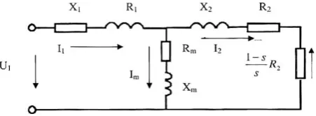
Fig. 1 shows the induction motor equivalent circuit model constructed by using the following set of parameters: (R1,𝑋𝑋1𝜎𝜎), (Rm, Xm) and (R2
Fig. 1 The equivalent circuit of an induction motor.
U
,𝑋𝑋2𝜎𝜎). Each pair represents resistance and leakage reactance respectively. The first pair deals with the stator parameters, second pair of parameters gives magnetising effects and air gap flux within the induction motor, while the third one with the rotor parameters.
i (per phase supply voltage of the stator) and I1, Im,I2
(the phase currents of stator, magnetising and rotor circuit respectively). By using the standard equivalent scheme, ohm’s law is applied to calculate the required electromagnetic losses as follows:
𝑃𝑃𝑔𝑔𝑜𝑜1 =𝑀𝑀𝑅𝑅1𝐼𝐼12 (Stator copper losses) (10) 𝑃𝑃𝑎𝑎=𝑀𝑀𝑅𝑅𝑎𝑎𝐼𝐼𝑎𝑎2 (Stator core losses) (11)
𝑃𝑃𝑔𝑔𝑜𝑜2 =𝑀𝑀𝑅𝑅2𝐼𝐼22 (Rotor copper losses) (12) Where M is the phase number of motor (in this case M=3), equations (10)-(12) are used with the values for the phase currents by:
𝐼𝐼1=𝑍𝑍1𝜎𝜎𝑍𝑍𝑎𝑎𝑈𝑈1+(𝑍𝑍𝑍𝑍1𝑎𝑎𝜎𝜎+𝑍𝑍𝑍𝑍22+)𝑍𝑍𝑎𝑎𝑍𝑍2 (13)
𝐼𝐼2=𝑍𝑍1𝜎𝜎𝑍𝑍𝑎𝑎+𝑈𝑈𝑍𝑍11𝑍𝑍𝜎𝜎𝑎𝑎𝑍𝑍2+𝑍𝑍𝑎𝑎𝑍𝑍2 (14)
𝐼𝐼𝑎𝑎=𝑍𝑍1𝜎𝜎𝑍𝑍𝑎𝑎+𝑈𝑈𝑍𝑍11𝜎𝜎𝑍𝑍2𝑍𝑍2+𝑍𝑍𝑎𝑎𝑍𝑍2 (15)
Where 𝑍𝑍1𝜎𝜎,𝑍𝑍𝑎𝑎 and Z2
Where 𝑋𝑋1𝜎𝜎, 𝑋𝑋2𝜎𝜎 and X
are the phase independence of stator, magnetising and rotor circuit, respectively.
𝑍𝑍1𝜎𝜎 =𝑅𝑅1+𝑗𝑗𝑋𝑋1𝜎𝜎, 𝑍𝑍2=𝑅𝑅𝑐𝑐2+𝑗𝑗𝑋𝑋2𝜎𝜎,
𝑍𝑍𝑎𝑎=𝑅𝑅𝑎𝑎+𝑗𝑗𝑋𝑋𝑎𝑎 (16)
m are the leakage reactance. Next
183 Copyright © 2011-15. Vandana Publications. All Rights Reserved.
mechanism parameters. All three main heat transfer mechanisms, conduction, radiation and convection are involved in the heat exchange in TEFC type motors [18]. 2. Heat transfer in induction motors via conduction and radiation
In the solid parts of motors, such as the rotor and stator, heat is typically transferred by conduction. Hence, for these parts we use the standard Fourier’s law to connect the heat flux and the temperature gradient:
𝑞𝑞=−𝑘𝑘∇𝑇𝑇 (17)
Temperature gradient ∇𝑇𝑇 is the function of GroCE temperature Tgce which is in logarithmic relationship
with stator temperature of motor.
A part of heat in induction motors is transferred by radiation. The actual amount of energy transferred in the form of electromagnetic waves depends not only on the emissivity properties of the part of the motor under consideration but also on the temperature itself in a strongly non-linear way [19]. Due to a temperature difference between the motor surface and the surrounding temperature which is modelled as GroCE temperature Tgce, the heat will be radiated out from the
whole of the motor surface and the energy radiated can be evaluated according to Stefan-Boltzmann law of radiation
𝑒𝑒=𝜖𝜖𝜎𝜎𝜖𝜖(𝑇𝑇𝑐𝑐4− 𝑇𝑇𝑔𝑔𝑔𝑔𝑔𝑔4 ) (18)
Where A is the surface area of the motor under consideration, 𝜖𝜖 is the emissivity coefficient and 𝜎𝜎 =5.67 * 10-8
Fig.2 Air flow path of induction motor.
The main parts of the motor where convection model is used for the heat transfer in air gap from shafts, from the rotor, shaft ends and magnetic bearings, in the winding space. The expression for the fluid of such forced. Convection is given in the form,
𝑞𝑞=ℎ(𝑇𝑇 − 𝑇𝑇𝑔𝑔𝑔𝑔𝑔𝑔) (19)
Where, T is the surface temperature and T 𝑊𝑊 𝑎𝑎⁄ 2𝐾𝐾4 is the Stefan –Boltzmann constant. 3. Heat transfer in induction motor via conduction
The motor analysed in this paper as a case study on TEFC with an external fan. This will cause force convection on the frame of motor which is shown in fig. 2.
gce
In evaluating the convection coefficient h for the heat transfer from frame to the external environment, heat dissipated from the fins of frame (denoted by h
includes the temperature of air fluid and external environment.
a)
and heat dissipated from the surface between the fins (denoted by hl) are also taken into account[20]. A
method for calculating the forced convection coefficient depending on the Reynolds number:
𝑅𝑅𝑔𝑔 =𝑉𝑉𝑎𝑎𝜅𝜅𝐹𝐹𝑣𝑣 (20)
Where, Va is the air flow velocity at beginning of the
fins, Fl is the axial length of the fins and 𝜿𝜿 is the
kinematic viscosity of the air.
General procedure for the evaluation of ha and hl,
on the basis of Reynolds number procedure follows one of the following two directions.
a. Laminar airflow case
In this case overall heat transfer H’ can be defined as,
𝐻𝐻′=0.7(𝑅𝑅𝑔𝑔)
0.5�1−0.12 �𝐹𝐹ℎ
𝐹𝐹𝑤𝑤�
1�3
�𝐾𝐾
𝐹𝐹𝑣𝑣 (21)
Where Fw is the distance between two fins and Fh is the
height of the fins and K is the thermal conductivity of air then connection coefficient is calculated which is related to the dissipation from the fins of the frame as follows:
ℎ𝑎𝑎 =𝐻𝐻′[1−0.02(𝐹𝐹𝐹𝐹𝑤𝑤ℎ)] (22)
And the value of connection coefficient related to the dissipation from the surface between the fins as,
ℎ𝑣𝑣 =
0.7 (𝑅𝑅𝑔𝑔)0.5�1−0.35 �𝐹𝐹ℎ
𝐹𝐹𝑤𝑤
� �1�3�𝐾𝐾
𝐹𝐹𝑣𝑣 (23)
b. Turbulent airflow case
In this case H’ is calculated as,
𝐻𝐻′=0.035𝑅𝑅𝑔𝑔
0.6�1−0.09 �𝐹𝐹ℎ
𝐹𝐹𝑤𝑤
� �0.5�𝐾𝐾
𝐹𝐹𝑣𝑣 (24)
Ha is calculated by using equation (22) while for the
calculation of hl
In this paper, a mathematical thermal model GroCE, for accurate estimation of thermal conditions of cage rotor induction motors including the temperature variations due to climatic effect is developed. Limitations of previously developed thermal models
following formula is used,
ℎ𝑣𝑣 =
0.03 (𝑅𝑅𝑔𝑔)0.8�1−0.23 �𝐹𝐹ℎ
𝐹𝐹𝑤𝑤
� �0.5�𝐾𝐾
𝐹𝐹𝑣𝑣 (25)
Finally for this convection coefficient including the climatic effect, following formula is used.
ℎ𝑓𝑓𝑣𝑣𝑔𝑔𝑔𝑔 = 6.5 + 0.05(𝑇𝑇 − 𝑇𝑇𝑔𝑔𝑔𝑔𝑔𝑔) (26)
184 Copyright © 2011-15. Vandana Publications. All Rights Reserved.
which consider the motor’s surrounding temperature as constant are eliminated by GroCE model. This model can be applied for various frequency and loads as well as identified temperature that can be compared to the thermal limits and alarm thresholds to prevent motors from overheating and damage.
This model is helpful for designing aspects of induction motors in efficiency improvement and better thermal withstanding capacity.
REFERENCES
[1] B. Khan and A. Goyal., Efficiency improvement of three phase induction motor using WCCA method, International Journal for Research in Applied Science and Engineering Technology, 3(1): 190-195, January 2015.
[2] B. Khan and A. Goyal., Improving thermal withstanding capacity of single phase induction motor using NWCC method, International Journal of Scientific Research and Development, 2(11): 470-475, 2015. [3] B. Khan, A. Goyal and A.K. Choubey., Improving thermal withstanding capacity of three phase induction motor using NWCC method, International Journal of Research- Granthaalayah, 2(3): 40-51, 2014.
[4] R. Beguenane and M.E.H. Benbouzid., Induction motor thermal monitoring by means of rotor resistance identification, IEEE Transactions on Energy Conversation, 14(3): 566-570, 1999.
[5] M.J. Duran and J. Fernandez., Lumped-parameter thermal model of induction machines, IEEE Transactions on Energy Conversion, 19(4): 791-792, 2004.
[6] P.K. Vong and D. Rodger., Coupled electromagnetic thermal modelling of electrical machines, IEEE Transactions on Magnetics, 39(3): 1614-1617, 2003. [7] S. Mezani , N. Takorabet and B. Laporte., A combined electromagnetic and thermal analysis of induction motors, IEEE Transactions on Magnetics, 41(5): 1572-1575, 2005.
[8] D. Staton, A. Boglietti and A. Cavagnino., Solving the more difficult aspect of electric motor thermal analysis in small and medium size induction motors, IEEE Transactions on Energy Conservation, 20(3): 620-628, 2005.
[9] M.N. Sabry., High- precision compact thermal models, IEEE Transactions on Components and Packaging Technologies, 28(4): 623-629, 2005.
[10] S.C. Mukhopadhyay and S.K. Pal., Temperature analysis of induction motors using a hybrid thermal model with distributed heat sources, Journal of Applied Physics, 83(11):6368-6370, 1998.
[11] R.V.N. Melnik, A.J. Roberts and K.A. Thomas., Phase transition in SMA with hyperbolic heat conduction and differential-algebraic models, Computational Mechanics, 29: 16-26, 2002.
[12] M.N. Ozisik., Heat conduction, second ed., John Wiley & Sons, 1993.
[13] B. Khan and A. Goyal, WCCA method: A method for improving the efficiency of single phase induction
motor, Integrated Journal of Engineering Research and Technology, 2(1), in press, 2015.
[14] P.S. Bhimbhra., Electrical machinery, seventh ed., Khanna Publishers, 2007.
[15] D.P. Kothari and I.J. Nagrath., Electrical machines, third ed., Tata McGraw-Hill Education, 2004.
[16] A. Mihalcea, B. Szabados and J. Hoolboom., Determining total losses and temperature rise in induction motors using equivalent loading methods, IEEE Transactions on Energy Conservation, 16(3): 214-219, 2001.
[17] H.A. Toliyat, T.A. Lipo and J.C. White., Analysis of a concentrated winding induction machine for adjustable speed drive applications, IEEE Transactions on Energy Conservation, 6(4): 679-692, 1991.
[18] S.C. Mukhopadhyay., Prediction of thermal condition of cage rotor induction motors under non-standard supply systems, International Journal on Smart Sensing and Intelligent Systems, 2(3): 381-394, 2009. [19] L.I. Zhu and X.J. Zheng., A theory for electromagnetic heat conduction and a numerical model based on Boltzmann equation, International Journal of Nonlinear Sciences and Numerical Simulation, 7(3): 339- 344, 2006.