209 Copyright © 2011-15. Vandana Publications. All Rights Reserved.
Volume-5, Issue-1, February-2015
International Journal of Engineering and Management Research
Page Number: 209-216
Cold Forging of Rivet Shape Head from Cylindrical Porous Aluminum
Specimen at Different Strain Rates
Shrikant Jain1, Dr. R. K. Ranjan2, Dr. Surrender Kumar3
1
Department of Mechanical Engineering, GGITS, Jabalpur, INDIA
2
Department of Mechanical Engineering, GGITS, Jabalpur, INDIA
3
Dean R & D, G.L.A University, Mathura, INDIA
ABSTRACT
The paper presents an investigation into the problem of shape heading under low – velocity dynamic forging conditions where the initially circular aluminum powder porous specimen clamped at one of its ends, is headed into a circular shaped head rivet. Yield criterion, friction law, chosen velocity field an upper bound approach have been considered to develop a mathematical model for the relative average forging pressure on the specimen at different strain rate. The specimens were prepared and subjected to rivet head forging process at different strain rates: 1.5, 50, 100 and 150 mm/min under lubricated end conditions. Parametric analysis giving the variation of the relative average forging pressure versus percentage reduction in height of the specimen during rivet head forging process was presented graphically. Theoretically and experimentally obtained values of forging load versus percentage reduction in height of the specimen during the process were plotted and a good correlation was observed. Strain rate effect on forging load during circular rivet head forming process versus percentage reduction in height were presented graphically, analyzed and discussed critically.
Keywords— Porous aluminum specimen, rivet shaped heading,
strain rate, yield criterion,
I.
INTRODUCTION
Sintered metal powder porous specimen forging has the advantages associated with conventional powder metallurgical processes, as the additional strength is provided by the elimination of porosity as discussed by Cull (1970) [1]. Jha and Kumar (1988) [2] investigated the influence of powder particle size, compacting pressure, sintering temperature, and forging parameters on relative density of the specimen along with the deformation characteristics and fracture mechanisms during the cold
forging of sintered iron powder specimen under axis-symmetric conditions.
Chitkara and Bhutta (2001) [3] had dealt the problem for solid circular rod to head into a triangular, hexagonal, and octagonal shaped heads. The shape heading was accomplished in three stages i.e. the upsetting stage, cavity filling or head forming stage and flash formation stage. They showed in their investigation that in dynamic shape heading of triangular, hexagonal, and octagonal shaped heads, the dynamic die loads are 20- 40 % higher than the static loading. Singh and Jha (2001) [4] have analyzed the dynamic effects during high speed forging of sintered porous specimens by energy method for axisymmetric and plain strain conditions. They have shown that die velocity has significant effect on deformation characteristics. Ranjan and Kumar (2004) [5] presented a generalized solution to determine die pressure for high speed forging of N-sided polygonal sintered powder disc. Ranjan and Kumar (2004) [6] used an upper bound approach to determine the die pressure in closed die forging of hexagonal porous specimen. Sumathi and Selvakumar (2012) [7] have investigated the workability of sintered copper-silicon carbide specimens during cold axial upsetting. They showed that strength property is very high at 5 % of SiC with copper and with higher value of SiC addition, the initiation of crack appeared at a low axial strain. Verma et.al (2013) [8] have investigated the deformation characteristics during open-die forging of silicon carbide particulate reinforced aluminum metal matrix composites (Si-Cp AMC) at cold conditions. No one has carried out investigation on cold forging of rivet shaped head from cylindrical sintered porous specimen at different strain rates.
210 Copyright © 2011-15. Vandana Publications. All Rights Reserved.
clamped at one of its ends is headed into a circular shaped head rivet at different strain rates, considering upsetting and head formation in one stage only. A mathematical model has been developed to show the variation of the relative average forging pressure versus percentage reduction in height during the head forming process. The appropriateness of the obtained theoretical results has been verified experimentally.
II.
THEORY
Yield Criterion for Porous Metallic Specimen Basic Assumptions:-
The material of the porous specimen is isotropic
rigid plastic but compressible with volume inconstancy.
The density distribution is non-uniform throughout
the deforming process.
The yielding is sensitive to hydrostatic stress.
The deformation is inhomogeneous and barreling is
considered.
Coefficient of friction is constant and both sliding
and sticking friction are considered. The friction due to adhesion (sticking friction) has considered as
function of relative density ρr
The forging die-faces are flat and rigid.
.
Pressure is normal to the contact-surfaces of the
dies.
Elastic deformation is neglected.
Tabata and Masaki (1978) [9] proposed the following yield criterion;
ρkσ
o=�3J2/± 3ησm (1)
(-) sign is for compressive load and η ≤ 0. The values of
η and k were determined experimentally:
η= 0.54(1− ρ)1.2 , k = 2, for σ
m ≤0 (2)
For axisymmetric conditions the equation (1), becomes
σ1= ρ
kσo
(1−2η)+
(1+η)
(1−2η)σ2 (3)
The moment yielding starts the equation reduces to give flow stress as
λ=(1ρ−kσo2η) (4)
According to Tabata and Masaki (1978) [9] the principal strain increments are given as
dεi= dλ[3(σi−σm)
2�3J2/ ±η]
, (for i = 1, 2, 3) (5)
where
dλ=√32�(dε1−dε2)2+ (dε2−dε3)2+ (dε3−dε1)2
a positive constant, the volumetric strain increment dεv is
given as
dεv = dε1+ dε2+ dε3= ±3ηdλ= ±μ√2η[(dε1− dε2)2+(dε2−dε3)2+(dε3−dε1)2]12 (6)
For axisymmetric compression it yields the compatibility equation as
εr =(22(η−η+1)1)lnhh21 (7)
Frictional condition between deforming tool and work piece in metal forming are of great importance and depends upon various factors discussed by Derygin (1952) [10]. The relative velocity between the work piece materials creates the conditions essential for adhesion in addition to sliding. During plastic deformation of metal powder porous specimen mechanism of composite friction occurs and the shear stress equation becomes
𝜏𝜏=𝜇𝜇(𝑝𝑝+𝜌𝜌0𝜙𝜙0) (8)
Forging of Cylindrical Porous Specimen into Rivet at Different Strain Rates:
Mathematical Analysis:
Figure 1 shows the cylindrical porous specimen in shaped heading process. One end of the cylindrical sintered powder porous specimen is clamped at lower end of the die set. The punch has circular cavity to give the shape of circular rivet of 5 mm head thickness. The punch
moves down ward with velocity Uo and lower platen
remains stationary. An upper bound analysis is considered in “near-net” shape dynamic heading at different strain rates.
During the axisymmetric shaped heading process, the porous specimen is subdivided into two zones of deformation. In zone 1, the case is similar to the axisymmetric forging of cylindrical porous specimen between two flat platens at different strain rates and the bulged profiles of the compressed porous specimens were observed as shown in figure 2. Form the traced profile of compressed porous specimen, velocity field was ascertained which was similar to the velocity field chosen
211 Copyright © 2011-15. Vandana Publications. All Rights Reserved.
Figure 1: Cylindrical porous specimen in shaped heading process.
Figure 2: Compressed porous specimen with bulged profile
Velocity fields and Strain rates:-
𝑈𝑈𝑧𝑧 =−2𝑈𝑈0𝑍𝑍3𝑎𝑎 −𝑈𝑈0𝑍𝑍 2
3𝑎𝑎2 �2−𝑍𝑍
2
𝑎𝑎2� (9)
𝑈𝑈𝜃𝜃 = 0 10)
𝑈𝑈𝑟𝑟 =𝐾𝐾 �𝑈𝑈30𝑎𝑎𝑟𝑟+2𝑈𝑈3𝑎𝑎0𝑍𝑍𝑟𝑟2 �1− 𝑍𝑍2
𝑎𝑎2�� (11)
Strain rates:
𝜀𝜀𝑟𝑟̇ =∂∂Urr =𝐾𝐾 �3𝑈𝑈0𝑎𝑎+23𝑈𝑈0𝑍𝑍𝑎𝑎2 �1− 𝑍𝑍2
𝑎𝑎2�� (12)
𝜀𝜀𝜃𝜃̇ =U𝑟𝑟r+1𝑟𝑟∂∂θUθ=𝐾𝐾 �𝑈𝑈03𝑎𝑎+23𝑈𝑈0𝑍𝑍𝑎𝑎2 �1−𝑍𝑍 2
𝑎𝑎2��=𝜀𝜀𝑟𝑟̇ (13)
𝜀𝜀𝑧𝑧̇ =−2�𝑈𝑈3𝑎𝑎0+23𝑈𝑈𝑎𝑎02𝑍𝑍�1− 𝑍𝑍2
𝑎𝑎2�� (14)
The value of K is determined by using Tabata & Masaki (1978) [9] compressibility equation
(𝜀𝜀𝑟𝑟̇ +𝜀𝜀𝜃𝜃̇ +𝜀𝜀𝑧𝑧̇) =
±2𝜂𝜂�(𝜀𝜀𝑟𝑟̇ − 𝜀𝜀𝜃𝜃̇)2+ (𝜀𝜀𝜃𝜃̇ − 𝜀𝜀𝑧𝑧̇)2+ (𝜀𝜀𝑧𝑧̇ − 𝜀𝜀𝑟𝑟̇)2 (15)
substituting the strain rates in compressibility equation (15) and solving for compressive load condition, gives
𝐾𝐾=(1(1+−2𝜂𝜂𝜂𝜂)) (16)
Internal power of deformation (𝑊𝑊𝑖𝑖):
𝑊𝑊𝑖𝑖 =√23𝜎𝜎0∗∫ �12𝜀𝜀𝑖𝑖𝑖𝑖̇ 𝜀𝜀𝑖𝑖𝑖𝑖̇ 𝑑𝑑𝑑𝑑 ∵ 𝑑𝑑𝑑𝑑= 2𝜋𝜋𝑟𝑟𝑑𝑑𝑟𝑟𝑑𝑑𝑧𝑧
(17)
𝑊𝑊𝑖𝑖 =2𝜋𝜋√2
√3 𝜎𝜎0∗� ��𝜀𝜀𝑟𝑟̇2+𝜀𝜀𝜃𝜃̇2+𝜀𝜀𝑧𝑧̇2�𝑟𝑟𝑑𝑑𝑟𝑟𝑑𝑑𝑧𝑧
substituting the value of strain rates
𝑊𝑊𝑖𝑖 =4𝜋𝜋�(𝐾𝐾
2+ 2)
√3 𝜎𝜎0∗ � � � 2𝑈𝑈0
3𝑎𝑎
𝑎𝑎
0
𝑟𝑟0
𝑟𝑟=0
+83𝑈𝑈𝑎𝑎02𝑍𝑍�1−4𝑎𝑎𝑍𝑍22�� 𝑟𝑟𝑑𝑑𝑟𝑟 𝑑𝑑𝑧𝑧
=�(𝐾𝐾2+2)
√3 (𝜋𝜋𝑟𝑟02)𝜎𝜎0∗𝑈𝑈0 (18)
Energy dissipation due to Velocity discontinuity (𝑊𝑊𝑑𝑑):-
At Z= a (top) surfaces the velocity discontinuity is
|∆𝑉𝑉| =𝐾𝐾 �𝑈𝑈0𝑟𝑟3𝑎𝑎� (19)
𝑊𝑊𝑑𝑑= 2 𝜋𝜋𝜎𝜎0∗�|∆𝑉𝑉|𝑟𝑟𝑑𝑑𝑟𝑟
𝑟𝑟0
0
𝑊𝑊𝑑𝑑=2𝜋𝜋𝑟𝑟0 3𝜎𝜎
0∗𝑈𝑈0𝐾𝐾
9𝑎𝑎 (20)
Frictional power losses (𝑊𝑊𝑓𝑓):-
Both at top and bottom surfaces Z=0 & Z= a, the
velocity discontinuity is: |∆𝑉𝑉| =𝐾𝐾 �𝑈𝑈0𝑟𝑟
3𝑎𝑎�
The energy dissipation rate due to friction at the tool metal interfaces is given by
𝑊𝑊𝑓𝑓𝑓𝑓=
2𝜋𝜋 �∫ 𝐾𝐾 �U0𝑟𝑟
3𝑎𝑎� 𝑟𝑟𝑒𝑒𝑒𝑒
0 + ∫ 𝐾𝐾 � U0𝑟𝑟
3𝑎𝑎� 𝑟𝑟𝑒𝑒𝑒𝑒
𝑟𝑟𝑜𝑜 �τ|∆𝑈𝑈|𝑟𝑟𝑑𝑑𝑟𝑟=
𝑊𝑊𝑓𝑓𝑓𝑓1+ 𝑊𝑊𝑓𝑓𝑓𝑓2 (21)
rex is new expanded radius of the specimen.
212 Copyright © 2011-15. Vandana Publications. All Rights Reserved.
the centre and in its vicinity and rest of the outer area of contact surface is a sliding zone. The shear stress as given by Rooks (1974) [11]
𝜏𝜏=𝜇𝜇 �𝑝𝑝̅+𝜌𝜌0∅0�1−𝑟𝑟𝑚𝑚𝑛𝑛𝑟𝑟0−𝑟𝑟�� (22)
Sticking radius 𝑟𝑟𝑚𝑚 =𝑟𝑟 − �ℎ
2𝜇𝜇� 𝑙𝑙𝑛𝑛
1
√3𝜇𝜇 and n is a
constant, n>>1.
At top surface of the rivet head, i.e. z = a, r = 0 to
𝑟𝑟= 𝑟𝑟𝑒𝑒𝑒𝑒
𝑊𝑊𝑓𝑓𝑓𝑓1= 2𝜋𝜋 ∫ 𝜇𝜇𝐾𝐾0𝑟𝑟𝑒𝑒𝑒𝑒 �𝑝𝑝+ 𝜌𝜌0𝜑𝜑0�1−
𝑟𝑟𝑚𝑚−𝑟𝑟𝑛𝑛𝑟𝑟0 U0𝑟𝑟3𝑎𝑎𝑟𝑟𝑑𝑑𝑟𝑟
Putting 𝜌𝜌0𝜑𝜑0=𝑒𝑒.𝑝𝑝 & integrating
𝑊𝑊𝑓𝑓𝑓𝑓1=�2𝜋𝜋𝜇𝜇 𝑝𝑝
KU0
3𝑎𝑎 � �
𝑟𝑟𝑒𝑒𝑒𝑒3
3 +
𝑒𝑒.𝑟𝑟𝑒𝑒𝑒𝑒3
3 −
𝑒𝑒.𝑟𝑟𝑚𝑚.𝑟𝑟𝑒𝑒𝑒𝑒3 3𝑛𝑛𝑟𝑟0 +
𝑒𝑒.𝑟𝑟𝑒𝑒𝑒𝑒44𝑛𝑛𝑟𝑟0 (23)
Similarly at bottom surface of rivet head i.e. z = 0, r =r0
to r = rex
𝑊𝑊𝑓𝑓𝑓𝑓2=�2𝜋𝜋𝜇𝜇 𝑝𝑝3𝑎𝑎KU0� �(𝑟𝑟𝑒𝑒𝑒𝑒
3−𝑟𝑟 03)
3 +
𝑒𝑒.(𝑟𝑟𝑒𝑒𝑒𝑒3−𝑟𝑟03)
3 −
𝑒𝑒.𝑟𝑟𝑚𝑚. (𝑟𝑟𝑒𝑒𝑒𝑒3−𝑟𝑟03)3𝑛𝑛𝑟𝑟0 + 𝑒𝑒.(𝑟𝑟𝑒𝑒𝑒𝑒4−𝑟𝑟04)4𝑛𝑛𝑟𝑟0 (24)
total frictional power loss is given by adding the equations 23 & 24.
𝑊𝑊𝑓𝑓𝑓𝑓 = 2𝜋𝜋𝑟𝑟0 3𝜇𝜇 𝑝𝑝𝐾𝐾U0
9𝑎𝑎 ��1 + 𝑒𝑒 − 𝑒𝑒𝑟𝑟𝑚𝑚
𝑛𝑛𝑟𝑟0� �2� 𝑟𝑟𝑒𝑒𝑒𝑒
𝑟𝑟0�
3
−
1 + 3.𝑒𝑒𝑟𝑟𝑒𝑒𝑒𝑒4𝑛𝑛𝑟𝑟02𝑟𝑟𝑒𝑒𝑒𝑒𝑟𝑟04− 1 (25)
Energy dissipation due to Inertia (𝑊𝑊𝑎𝑎):-
Wa =ρp∫UiUi̇dv (24)
ρp
Uż =∂∂Ut + Uz r∂∂Ur +z Urθ∂∂θUz+ Uz∂∂Uzz
substituting the values
Uθ̇ = 0 (25)
𝑈𝑈𝑟𝑟̇ =𝐾𝐾 �3𝑟𝑟𝑎𝑎+23𝑍𝑍𝑟𝑟𝑎𝑎2�1− 𝑍𝑍2
𝑎𝑎2�� �𝑈𝑈̇ − 𝐾𝐾𝑈𝑈𝑜𝑜2�31𝑎𝑎+32𝑎𝑎𝑍𝑍2�1−
𝑍𝑍2𝑎𝑎2+𝑈𝑈02𝑟𝑟1−2𝐾𝐾𝑟𝑟3𝑎𝑎21−𝑍𝑍2𝑎𝑎22𝑍𝑍3𝑎𝑎+ 𝑍𝑍23𝑎𝑎22−𝑍𝑍2𝑎𝑎2
(26)
𝑈𝑈𝑧𝑧̇ =− �𝑈𝑈̇ − 𝑈𝑈0�32𝑎𝑎+34𝑎𝑎𝑧𝑧2−
3𝑧𝑧3
3𝑎𝑎2���
2𝑍𝑍
3𝑎𝑎+
𝑍𝑍2
3𝑎𝑎2�2−
𝑍𝑍2 𝑎𝑎2��
(27)
substituting the velocity and acceleration components in equation (24) and after integration
Wa= 2πr02U0ρp�U̇a�0.213K2�rao� 2
+ 0.167�+
Uo20.0439K2roa2+K4+0.056 (28)
External power supplied by the press:
During deformation the external powder J∗ supplied by
the ram
J∗= W
i+ Wv+ Wf+ Wa+ Wt (29)
The last term (Wt) is power supplied by predetermined
body tractions and since there is no surface traction so the value of W
- specimen density. The equation in expanded form
Wa = 2πρp � � �UrUṙ + UθUθ̇ + UzUż �rdr
r0
0
dz a
z=0
The acceleration-components Uṙ , Uθ̇ , and Uż in the
cylindrical coordinate system (r, θ, z) are:
Uṙ =∂∂Ut + Ur r∂∂Ur +r Urθ∂∂θUr+ Uz∂∂Uzr−U0 2 r
Uθ̇ =∂∂Ut + Uθ r∂∂Ur +θ Urθ∂∂θUθ+ Uz∂∂Uz +θ UθrUr
t is considered as zero. Therefore,
J∗=∫F
iU0ds = PU0= U0∫0r02πrp�dr=πr02p�U0 (30)
p� is average pressure on the specimen’s forging face.
Relative Average Forging Pressure:-
J∗=∫FiU0ds =πr02p� U0= Wi+ Wv+ Wf+ W
a (31)
Substituting the values of Wi, Wv, Wf, & Wa in
213 Copyright © 2011-15. Vandana Publications. All Rights Reserved.
III.
MATERIALS AND METHOD
The aluminum metal powder “Qualikem” make was compacted at a compaction pressure of 300 Mpa in a closed circular cavity of diameter 20 mm on 400 kN computerized UTM to fabricate the green compacts. These compacts were sintered in an endothermic atmosphere at
500 0
Figure 3: Die-set to fabricate rivet form sintered porous
specimen
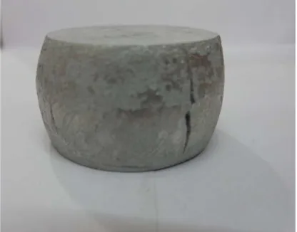
C for two hours in a muffle furnace. The density of the specimen was obtained simply by measuring dimensions and weight. The specimens had a relative density of 0.9 approximately. The specimen was forged in to a rivet by using closed rivet forming die set comprising of four components as shown in figure 3. One end of the specimen was clamped at the lower part of the die set. The punch of 30 mm diameter moves in a die component having cavity of 30 mm plus enclosing the upper part of the clamped specimen. The required travel of the punch is set to form the rivet. Figure 4 shows the arrangement of die components while forging the rivet on the UTM. Approximately 15 mm height of the specimen was used to form the rivet head of 30 mm diameter and 5 mm head thickness. Figures 5 & 6 show the formed rivet form the porous specimen. The forging was done at different strain rates on the UTM. The load with percentage reduction in height was recorded in the excel sheet.
Figure 2: Fabrication of rivet on UTM
Figure 3: Forged rivet from Aluminum porous specimen
Figure 4: Forged rivet from Aluminum porous specimen
IV.
RESULTS AND DISCUSSIONS
The density and modulus of elasticity of
aluminum metal were considered as 2.7 gm/cm3 and 70
GPa. The flow stress “σo
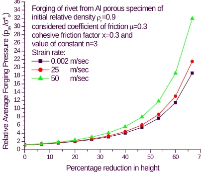
The parametric results are presented graphically. The variation of the relative average forging pressure versus percentage reduction in height of the porous specimen have been plotted using the equation (32) by changing one of the considered parameters. Figure 7 shows this variation for different values of strain rates. It is observed that for given percentage reduction in height as the strain rate increases the relative average forging pressure also increases. Figure 8 and figure 9 show this variation for different values of coefficient of friction and cohesive friction factor ‘x’ respectively. For considered percentage reduction in height as these values are
214 Copyright © 2011-15. Vandana Publications. All Rights Reserved.
increased the relative average forging pressure also increased. In figure 10 shows that with the increase in the value of constant ‘n’ the relative average forging pressure decreases.
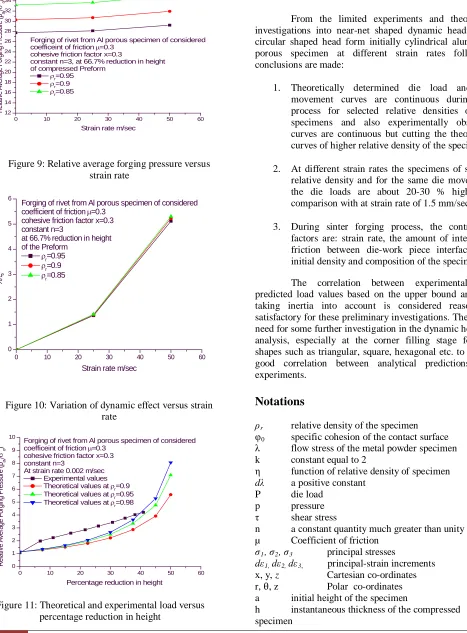
Figure 11 shows the variation of the relative average forging pressure versus strain rate at 50 percent height reduction for different values of specimen relative densities. Figure 12 shows the variations of dynamic effect with strain rate for different values of specimen relative densities. For considered strain rate, as the relative density increases the relative average forging pressure and the dynamic effect also increases. As the relative density increases the porosity of the specimen reduces resulting in higher relative average forging pressure.
The experimental results had been plotted as the variation of the relative average forging pressure versus percentage reduction in height, shown in figure 13, for the specimen of relative density 0.9, forged at strain rate 2 mm/sec. The experimental and theoretical results obtained using equation (32), were superimposed for the specimens of relative densities: 0.9, 0.95 and 0.98 and considered values of coefficient of friction 0.3, cohesive factor “x” 0.3 and constant n=3. A close agreement of experimental and theoretical results has been observed. As the forging pressure increases the compressed specimen density also increases, this is evident from the experimental result curve intersecting the theoretical results curves.
0 10 20 30 40 50 60 70
0 2 4 6 8 10 12 14 16 18 20 22 24 26 28 30 32 34 36
Forging of rivet from Al porous specimen of initial relative density ρr=0.9
considered coefficient of friction µ=0.3 cohesive friction factor x=0.3 and value of constant n=3
Strain rate: 0.002 m/sec 25 m/sec 50 m/sec
R el at iv e A v er age F or gi ng P res s ur e ( pa v / σ *o )
Percentage reduction in height
Figure 5: Relative average forging pressure versus percentage reduction in height
0 10 20 30 40 50 60 70
0 2 4 6 8 10 12 14 16 18 20 22 24 26 28 30 32 34 36
Forging of rivet from Al porous specimen of initial relative density ρr=0.9
considered cohesive friction factor x=0.3 value of constant n=3 and
strain rate 50 m/Sec considered values of coefficient of friction
µ=0.1 µ=0.2 µ=0.3 R el at iv e A ver age F or gi ng P res sur e ( pav / σ *o )
Percentage reduction in height
Figure 6: Relative average forging pressure versus percentage reduction in height
0 10 20 30 40 50 60 70
0 2 4 6 8 10 12 14 16 18 20 22 24 26 28 30 32 34 36
Forging of rivet from Al porous specimen of initial relative density ρr=0.9
considered coefficient of friction µ=0.3 value of constant n=3 and
strain rate 50 m/Sec Cohesive friction factors
x=0.1 x=0.2 x=0.3 R el at iv e A ver age F or gi ng P res sur e (
pav
/
σ
*o
)
Percentage reduction in height
Figure 7: Relative average forging pressure versus percentage reduction in height.
0 10 20 30 40 50 60 70
0 10 20 30 40 50
Forging of rivet from Al porous specimen of initial relative density ρr=0.9
considered coefficient of friction µ=0.3 cohesive friction factor x=0.3 and strain rate 50 m/Sec
values of constant n=1 n=2 n=3 R el at iv e A ver age F or gi ng P res sur e ( pav / σ *o )
Percentage reduction in height
215 Copyright © 2011-15. Vandana Publications. All Rights Reserved.
0 10 20 30 40 50 60
12 14 16 18 20 22 24 26 28 30 32 34 36
Forging of rivet from Al porous specimen of considered coefficeint of friction µ=0.3
cohesive friction factor x=0.3
constant n=3, at 66.7% reduction in height of compressed Preform
ρr=0.95
ρr=0.9
ρr=0.85
R el at iv e A ver age F or gi ng P res sur e ( pav / σ *o )
Strain rate m/sec
Figure 9: Relative average forging pressure versus strain rate
0 10 20 30 40 50 60
0 1 2 3 4 5 6
Forging of rivet from Al porous specimen of considered
coefficient of friction µ=0.3
cohesive friction factor x=0.3 constant n=3
at 66.7% reduction in height of the Preform
ρr=0.95
ρr=0.9
ρr=0.85
%
ζ
Strain rate m/sec
Figure 10: Variation of dynamic effect versus strain rate
0 10 20 30 40 50 60
0 1 2 3 4 5 6 7 8 9 10
Forging of rivet from Al porous specimen of considered coefficeint of friction µ=0.3
cohesive friction factor x=0.3 constant n=3
At strain rate 0.002 m/sec Experimental values Theoretical values at ρr=0.9
Theoretical values at ρr=0.95 Theoretical values at ρr=0.98
R el at iv e A ver age F or gi ng P res sur e ( pav / σ *o )
Percentage reduction in height
Figure 11: Theoretical and experimental load versus percentage reduction in height
V.
CONCLUSION
From the limited experiments and theoretical investigations into near-net shaped dynamic heading of circular shaped head form initially cylindrical aluminum porous specimen at different strain rates following conclusions are made:
1. Theoretically determined die load and die
movement curves are continuous during the process for selected relative densities of the specimens and also experimentally observed curves are continuous but cutting the theoretical curves of higher relative density of the specimens
2. At different strain rates the specimens of similar
relative density and for the same die movement, the die loads are about 20-30 % higher in comparison with at strain rate of 1.5 mm/sec.
3. During sinter forging process, the controlling
factors are: strain rate, the amount of interfacial friction between die-work piece interface, the initial density and composition of the specimen.
The correlation between experimental and predicted load values based on the upper bound analysis taking inertia into account is considered reasonably satisfactory for these preliminary investigations. There is a need for some further investigation in the dynamic heading analysis, especially at the corner filling stage for the shapes such as triangular, square, hexagonal etc. to obtain good correlation between analytical predictions and experiments.
Notations
ρr relative density of the specimen
φ0 specific cohesion of the contact surface
λ flow stress of the metal powder specimen
k constant equal to 2
η function of relative density of specimen
dλ a positive constant
P die load
p pressure
τ shear stress
n a constant quantity much greater than unity
µ Coefficient of friction
σ1, σ2, σ3 principal stresses
dε1, dε2, dε3,
a initial height of the specimen
h instantaneous thickness of the compressed
specimen
principal-strain increments
x, y, z Cartesian co-ordinates
216 Copyright © 2011-15. Vandana Publications. All Rights Reserved.
σ0 yield stress of the composite metal
σm hydrostatic stress
J’2 second invariant of the deviatoric stress
rm
1. Initial condition
radius of the sticking zone
Subscripts
2. Final condition
REFERENCES
[1] Cull, G.W., 1970. Mechanical and Metallurgical Properties of Powder Forging. Powder Metallurgy, vol. 13, no 26, p 156.
[2] Jha, A.K., and Kumar, S., 1988. Deformation Characteristics and Fracture Mechanism during the Cold Forging of Metal Powder Preform. Int. J. Mech. Tool Des. Res. vol.26, No.4, P 369.
[3] Chitkara, N. R. and Bhutta M. A., 2001. Dynamic Heading of Triangular, Hexagonal, and Octagonal Shaped Heads at High Impact Velocities: Some Experiments and an Analysis, International Journal Advanced Manufacturing Technology, vol.18 pp. 332- 347.
[4] Singh, S. and Jha, A.K., 2001. Analysis of Dynamic Effects During High Sped Forging of Sintered Preforms. Journal of Materials Processing Technology, Elsevier, vol.112 pp. 53.
[5] R. K. Ranjan and S. Kumar, 2004. High Speed Forging of Solid Powder Polygonal Discs with Bulging, Tamkang Journal of Science and Engineering, Vol. 7, No. 4, pp 219-226
[6] R. K. Ranjan and S. Kumar, June 2004. An Upper Bound Solution for Closed Die Sinter Forging of Hexagonal Shapes, S¯adhan ¯ a Vol. 29, Part 3, , pp. 263–273. © Printed in India
[7] Sumathi, M. and Selvakumar, N., April 2012. An Investigation on the Workability of Sintered Copper-Silicon Carbide Preforms During Cold Axial Upsetting. Indian Journal of Engineering & Materials Sciences vol.19. pp 121-12.
[8] Verma Deep, P. Chandrasekhar, S. Singh and S. Kar, 2013. Investigations into Deformation Characteristics during Open-Die Forging of SiCp Reinforced Aluminium Metal Matrix Composites. Research Article, Hindawi Publishing Corporation, Journal of Powder Technology Vol.2013, Article ID 183713, 14 pages.
[9] Tabata, T. and Masaki, M., 1978. A Yield Criterion for Porous Metals and Analysis of Axial Compression of Porous Discs. Memories of Osaka Institute of Technology, Series-B. Science and Technology. vol.22, No. 2 p.45.
[10] Deryagin, B.V., 1952. What is Friction? Izd Akad Nauk, USSR.