WATER SENSOR FEEDBACK CONTROL SYSTEM
FOR SURFACE IRRIGATION
A. S. Humpherys, H. D. Fisher
ABSTRACT. A water sensor feedback control system was developed to control semiautomatic irrigation of basins and borders. When water reaches a sensor at a downfield irrigation cutoff point, a signal to terminate irrigation is sent via wire or infrared (IR) telemetry to a station controller or receiver at the upper end of the field. The sensor uses a monostable interface to strengthen the signal for wire transmission, and prevents continuous IR transmission during the time the sensor is immersed or remains wet. The water sensor controller, powered by a 12-V battery, uses a silicon controlled rectifier (SCR) triggered by the feedback signal to discharge a capacitor through an electric solenoid. The energized solenoid actuates a gate release or valve to terminate irrigation of one field segment and begin irrigation of another. The water sensor system was tested in a level basin irrigation system.
A sensor costs approximately U.S. $30, while single and dual station controllers cost about $65 to 80. Both can be portable to minimize the number of units required. Keywords. Surface irrigation, Water sensors, Feedback, Control.
T
he time required for water to advance to the end of an irrigated border or basin often varies from one field segment to the next, and from irrigation to irrigation, because of changes in soil water infiltration rates, hydraulic resistance due to crop growth stages, and water supply rates. Thus, an irrigator may have to visit his field several times during an irrigation to observe the water's advance, particularly for the first border or basin to be irrigated. This is particularly inconvenient at night. Automated or semiautomated irrigation systems with water sensors located near the lower end of the field to provide feedback control can reduce or eliminate the need for human monitoring.
Sensor feedback systems are used in different ways for irrigation control. Some use radio or infrared (IR) telemetry communication links while others use wire. Water sensors may signal completion of irrigation when placed near the end of a field, or multiple units may be used to determine rate of advance as described by Smith and Duke (1984), and Latimer and Reddell (1990). Feedback systems are usually used to begin or end an irrigation set by opening or closing gates or valves. The sensors are those that sense the presence of water in contrast to those commonly used in irrigation which sense soil moisture, such as tensiometers. Most water sensors consist of a pair of electrodes that, similar to a switch, close an electric circuit as they become short-circuited when immersed in water. They are usually designed and configured for use in a specific feedback system. Some
Article has been reviewed and approved for publication by the Soil and Water Div. of ASAE. Presented as ASAE Paper No. 88-2583.
Names of products or companies are shown for the benefit of the reader and do not imply endorsement or preferential treatment of the company or products shown by the USDA-Agricultural Research Service. The authors are Allan S. Humpherys, ASAE Member Engineer, Agricultural Engineer, and Herbert D. Fisher, Electronics Engineer, USDA-Agricultural Research Service, Soil and Water Management Research, Kimberly, Idaho.
systems control a gate directly, such as that described by King and Amend (1983) which uses radio telemetry. Others use a citizens' band radio for alarm only, while others use computer control as described by Kidwell (1983) and Latimer and Reddell (1990). Several types of farmer-innovated sensors and feedback systems, including a commercially produced system (Aquascon Sales, Ltd., 114 Killeaton St., St. Ives, 2075, Australia) used in Australia were noted by Merrylees and Rendell (1985). Other commercially produced systems use water sensors with radio telemetry to control irrigation gates in Australia (Orchard's, Leitchville Road, Box 327, Cohuna, 3568, Australia; Farm-Mate, RMB 1020, Mitiamo, 3573, Australia; John Padman Precision Irrigation, Australia; and Rural Design, 215 Allan Street, Kyabram, 3620, Australia). A pneumatic sensor developed in New Zealand is used in the "Wragge pneumatic system of automatic flood irrigation control" (State Rivers and Water Supply Commission, 1976).
This article describes a low-cost water sensor system developed to provide feedback control for semiautomatic irrigation gates or valves. The system includes a water sensor and controller with components to activate electric solenoids used to release gate latches or to perform other functions. The sensor system was tested in a level basin irrigation system.
SYSTEM DESCRIPTION
The water sensor system consists of a water sensor, station controller, and a wire or infrared (IR) telemetry communication link. In operation, the sensor determines the arrival of the water's advance to the desired irrigation cutoff point near the lower end of the field being irrigated. When water contacts the sensor, a signal is sent via wire or IR telemetry to a station controller located near the irrigation turnout at the upper end of the field. The controller energizes an electric solenoid to change irrigation sets by releasing a gate(s), or by actuating a
Monostable printed circuit board
Electrode wires
Sensor body
Coupling
Sensor body PVC pipe
Silicone seal
Sensor base PVC SAD Flat cap
Coupling
Slip plug (cement to
sensor base)
\_Air vent (4 mm) lectrode shield Electrodes
Stainless steel clamp
Anchor rod (brass welding rod) Cap (Removable)
+ 12 v
To Controller
SCR Drive
valve. Although the system was developed and tested in a level basin system, it can also be used in other surface irrigation systems.
WATER SENSOR
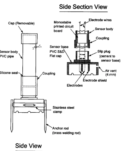
The water sensor consists of a pair of 3 mm (1/8 in.) stainless steel welding rod electrodes and a monostable interface mounted in a housing or sensor body made from PVC pipe components as shown in the diagram of figure 1. The electrodes extend from inside the base into the sensor body where they are attached to a monostable circuit. Stainless steel solder is used to attach wire conductors to the electrodes. An electrode shield around one electrode, made from 13 mm (1/2 in.) diameter low pressure PVC pipe, prevents the electrodes from becoming short-circuited by moisture inside the base.
The monostable interface produces a single electrical pulse when water contacts the sensor. This pulse is used to trigger a silicon controller rectifier (SCR), or to initiate a telemetry signal. A diagram of the interface circuit is shown in figure 2. The circuit is mounted on a 38 x 38 mm (1.5 x 1.5 in.) printed circuit board and is installed in the upper part of the sensor body as shown in figure 1, or in an IR transmitter. When used with telemetry, the monostable interface prevents continuous signal transmission while the sensor electrodes are still wet or immersed in water. With wire communication between sensor and controller, the interface, driven by a 9-V transistor battery, strengthens the feedback signal so longer distances can be used. As soon as water recedes from the field and the sensor becomes dry, the monostable interface automatically resets itself in readiness for the next irrigation.
Side Section View
Side View
Figure 1—Schematic diagram of a water sensor for feedback control of an irrigation gate.
Water sensor electrodes
Figure 2—Electrical diagram of monostable interface circuit used with a water sensor.
The water sensor body consists of a 100 mm (4 in.) length of 30 mm (1 1/4 in.) nominal diameter 865 kPa (125 psi) PVC pipe and associated fittings cemented to the flat top of a nominal 100 mm (4 in.) diameter sewer and drain (S & D) PVC cap which forms the sensor base as shown in figure 1. The base has water access holes or notches around its lower edge and an air bleed at the top. This size base is used to provide stability and support, and thus, maintain a small distance between the electrodes and ground surface. If desired, the sensor may be held in place on the ground by short 6 mm (1/4 in.) diameter brazing rod anchors attached to the sensor base with a stainless steel clamp band. The 865 kPa (125 psi) pressure rated pipe for the top of the body is used because its inside diameter is large enough to receive the monostable circuit board. The water sensor can be used for applications other than sensing an advancing water front over soil. For example, it can be used to sense the water surface in a ditch or stilling well. For these applications, the sensor body is simplified and the wide base need not be used. The simplified body consists of only the 30 mm (1 1/4 in.) diameter pipe with a cap on top and an inverted slip plug, with an air bleed, cemented to its bottom end. The plug is inverted to provide protection for the electrodes. The sensor is positioned as desired and clamped to a suitable mount.
WATER SENSOR STATION CONTROLLERS
(a) (b) Water sensors R, MC/
Rt. 680 fl C = 22,000 Ili L = Solenoid S = Switch
R,
Timer
I2v
S = Switch fi 1 = IK.0, R2 68011 C = 22,000W L = Solenoid
I2 v
Figure 3–Electrical diagram for a single station water sensor controller with (a) water sensor only, and (b) a mechanical timer backup.
of 900 m (3000 ft). Tests conducted beneath a power line showed no adverse effects from induced voltages.
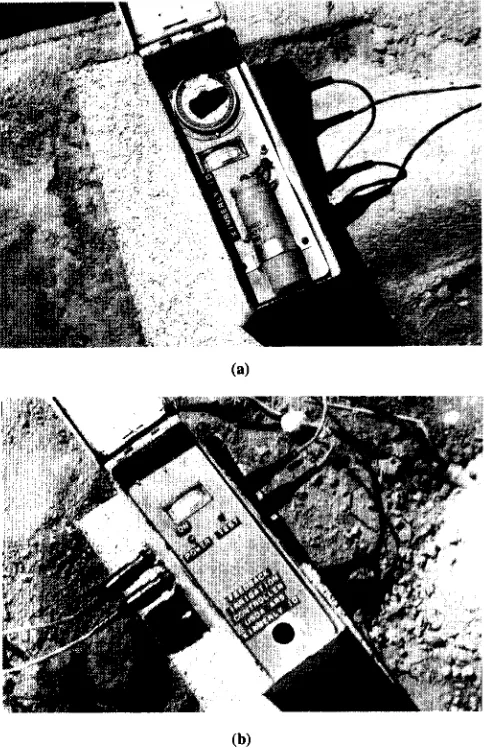
Both single- and dual-station water sensor controllers were tested. A single-station controller was assembled with a mechanical timer backup for field testing (fig. 3b) in a military surplus 30-caliber ammunition box as shown in figure 5a. To enhance operator confidence and avoid problems resulting from a dead battery, a low-cost voltmeter was installed in the controller. Battery condition was determined before an irrigation by momentarily depressing a test button. The controllers are made portable by fitting them with quick-connect/disconnect wire couplers for making connections to the sensor wire and gate solenoid (fig. 5). The dual-station controllers use a single battery and capacitor for both stations as shown in the diagram of figure 4.
A sensor and controller are needed for each gate solenoid to be operated. By using a three-conductor wire cable in or on a dike separating two borders or field segments to be controlled, one sensor can serve both
Water sensor 1 Water sensor 2
Figure 4–Electrical diagram for a dual-station water sensor controller.
(b)
Figure 5–Water sensor station controllers: (a) single station with a mechanical timer and (b) dual station.
borders by connecting the sensor to the common and either one communication conductor or the other. A two-station controller at the head end of the field can serve two lands if located relatively close to the two "first" gates of a trip-cord gate release system (Humpherys, 1995); otherwise, two single-station controllers would be used.
In operation, all sensor connections should be made before turning the station controller on, because electrical transients or static electricity may occasionally trigger the SCR if connections are made after the unit is turned on. Approximately 1 min is required to charge the capacitor after the controller switch is turned on. The solenoid will not operate until the capacitor is fully charged.
COMMUNICATION LINKS
four-conductor cable was installed near the dike separating two basins so it could serve both basins and, thus, need be installed only at every second dike. The cable was installed with a soil ripper which had a pipe welded to the rear edge of the shank to serve as a conduit for passing the wire cable from its supply reel into the ground at the bottom end of the shank as the machine was pulled forward.
The cable was brought to a height of about 1 m (3 ft) above the field surface in a nominal 50 mm (2 in.) ABS stand pipe located about three-fourths of the basin length downfield. A flexible, stranded, two-conductor 15 m (50 ft) long "pigtail," with water sensor attached, was connected to the end of the buried cable by one of two quick-connect wire couplers mounted on opposite sides of the riser. Each coupler served one of the basins. The sensor pigtail allows the irrigation cutoff point to be adjusted from one location to another within the range of the pigtail.
An alternative to burying the control cable in a permanent dike, as in this field, is to support it on stakes similar to electric fence wire over a temporary dike or berm between irrigated field segments. Less costly wire could be used for this alternative.
IR Telemetry. The IR telemetry component of a water sensor system consists of a transmitter located near the lower end of the field and a receiver/controller located at the head of the field near the irrigation turnout. The IR system has a range of 1.7 km (1 mile). The transmitter, with a sensor and pigtail attached, is placed on the dike or berm which separates two basins or borders near the downfield cutoff point. The monostable circuit can be installed in the transmitter enclosure if desired. The receiver is located on the ditchbank near the first gate or valve to be operated. A solenoid driver, with its associated components, is mounted in the receiver enclosure and powered by the receiver battery. Unless additional IR units are used, the transmitter and receiver must be moved after every second border or basin is irrigated. IR telemetry may be the most feasible alternative where (1) there is not a permanent dike or field strip in which to bury a wire, (2) the sensor is used at a permanent location such as at a stilling well in a permanent crop, such as an orchard, or at a ditch monitoring station, (3) where a small number of units (i.e., 1 to 2) would be required, or (4) where monitoring stations are widely separated.
Radio Telemetry. Radio telemetry for the water sensor system was not tested because of licensing, interference problems, and cost. In the United States, IR telemetry is usually more feasible for this type of application.
FIELD TESTS
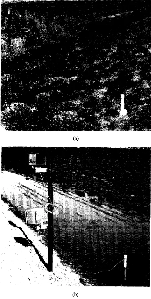
The water sensor system was tested in a level basin irrigation system with both wire and IR telemetry communication links. The sensor was placed on the ground surface near one edge of a basin about three-fourths of the basin length downfield as shown in figure 6. When the advancing water front reached the sensor, a feedback signal was transmitted to a station controller (fig. 5) or IR receiver at the head end of the field to terminate irrigation. The first of four gates serving the basin was released by an electric solenoid while the other gates were released by a trip-cord gate release system (Humpherys, 1995). Gates
(a)
(b)
Figure 6—Water sensor located near the lower end of a basin: (a) using buried wire communication to upper end of field, and (b) with an IR transmitter for IR telemetry communication.
serving the next basin in sequence could also be opened simultaneously with this system.
ASSEMBLY AND COSTS
City, Utah) for approximately $2 each in quantities of 18 circuit boards. The electronic components are soldered directly onto the circuit board by a technician. Parts for the sensor cost about $13 without the anchor rods, and the unit can be assembled for about $25 or $30 including labor; the simplified version, without the wide base, costs about $2 less.
Surplus, 30-caliber ammunition boxes, obtained from military surplus outlets, can serve as watertight, low-cost enclosures for the station controllers. Twelve-volt lantern batteries were used in the field test; however, if a controller is to be used extensively by being moved from field to field during the irrigation season, a rechargeable battery can be used. The voltmeter seen in figure 5 is optional and can be omitted to reduce cost. Battery voltage can be monitored by a portable voltmeter using jacks provided for this purpose. A timer is not required with the controllers; however, in certain special or critical situations, it may be desirable to provide a backup or to limit the maximum irrigation time. The timer we used was a 24-h mechanical timer with internal electrical contacts (Frank W. Murphy Manufacturing, Inc., Tulsa, Okla). Material costs for the basic single and dual station controllers without the optional features are about $30 and $40, respectively. The extra cost for the dual controller is primarily for the extra quick-connect couplers. Although less satisfactory, small 3 mm (1/8 in.) phone jacks, which cost about $3 less per connector, can be used. A controller can be assembled in about 2 h. Thus, depending upon labor costs, the basic cost for a station controller with battery will be in the $65 or $80 range.
IR transmitters and receivers cost about $250 each ($500/pair) (Automata, Inc., Grass Valley, Calif.), while
buried control wire used for center pivot sprinkler systems costs about $0.30/m ($0.105/ft). Thus, wire for a communication distance of 305 m (1000 ft) would cost about $105 plus installation. With one wire serving 2 borders, 10 borders could be equipped with wire for about the same cost as an IR transmitter/receiver pair if the farmer installed the wire himself. IR telemetry units would also require labor costs to move at every second border.
REFERENCES
Humpherys, A. S. 1995. Semiautomation of irrigated basins and borders: III. Control elements and system operation. Applied Engineering in Agriculture 11(1):83-91.
Kidwell, M. H. 1983. Automatic control of flood irrigation. In Agricultural Electronics – 1983 and Beyond, Vol. 1, Proc. ASAE Nat. Conf on Agric. Electronic Applications, 191-197, Chicago, Ill.
King, L. D. and J. R. Amend. 1983. Radio- or clock-activated semi-automatic irrigation gate controller. In Agricultural Electronics –1983 and Beyond, Vol. 1, Proc. ASAE Nat. Conf on Agric. Electronic Applications, 172-180, Chicago, Ill. Latimer, E. A. and D. L. Reddell. 1990. Components for an
advance rate feedback irrigation system (ARFIS). Transactions of the ASAE 33(4): 1162- 1170.
Merrylees, D. and R. Rendell. 1985. Automatic irrigation field day (notes). Rural Water Commission of Victoria, Kerang, 14 February.
Smith, D. L. and H. R. Duke. 1984. Prediction of irrigation advance rates in real time. ASAE Paper 84-2590. St. Joseph, Mich.: ASAE.