Copyright © 2015 IJECCE, All right reserved
Multivariable Decoupling Control System Based on
Generalized Diagonal Dominance
S. Jamebozorg
Department of Electrical Engineering, Imam Khomeini International University, Qazvin, Iran email: [email protected]
A. Shahmansoorian
Department of Electrical Engineering, Imam Khomeini International University, Qazvin, Iran email: [email protected]
Abstract: In this paper, the design of static precompensator for the reduction of interaction in linear multivariable systems is proposed. In the previous studies, the diagonal dominance of systems in special frequency range has been less paid attention to. In the proposed method, some static compensators with matrix coefficients are combined so that the final static compensator can make system diagonal dominance in a wide range of frequencies. These coefficients are obtained with optimization algorithm. In this method, to achieve diagonal dominance with less conservativeness, the criterion of generalized diagonal dominance is used. The proposed method does not have any limitation for systems with high interaction or non-minimum phase systems. In comparison with some common methods, it has a simpler structure with easy implementation. Simulation examples demonstrate the usefulness of the proposed method.
Keywords: Multivariable Systems, Decoupling System, Diagonal Dominance, Static Precompensator, PSO.
I.
I
NTRODUCTIONInteraction problem is one of the basic issues in the design of multivariable control systems. Therefore, in the theory of multivariable systems, there is a great attention to decoupling and design of non-interactive systems. Rosenbrock introduced inverse Nyquist array with a practical approach to interaction problem [1].In INA method, with the generalization of the Nyquist stability idea to multivariable systems, stability of closed loop syst-em can be found. As diagonal closed loop is practically difficult to perform, Rosenbrack proposed the diagonal dominance idea.
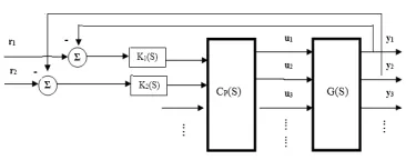
Fig. 1 shows the general decoupling control system, where G(s), Cp(s) and k(s) are the n-dimensional pro-cess matrix, the decoupler matrix and the diagonal control matrix, respectively. Decoupling control has been addressed in the literature [2,3,4]. Some decoupling schemes are static [5], and others are dynamic [6–11]. Complete decoupling of multivariable system involves using a complex compensator in series with transfer function matrix or fulfilling the limiting conditions in static feedback. In diagonal dominance idea, closed loop system is not necessarily completely diagonal. In this case, system is so compensated that the elements on main diameter dominate the other elements of transfer function matrix so that the designer designs a diagonal compensator consisting of classic simple compensators.
Figure.1. Block diagram of a decoupling system
Various methods have been proposed to determine a precompensator such that the compensated system is diagonally dominant. A pseudo diagonalization technique by Hawkins [12], an Align algorithm by MacFarlane and Kouvaritakis [13], scaling algorithms by mees [14], Munro [15] and Edmunds [16] and the optimization method by Bryant and Yeung [17] have all been proposed. However, all these algorithms and designed to obtain dominance at a particular frequency which is normally selected by trial and error. Nobakhti, Munro and Porter presented a genetic algorithms (GA) to achieve diagonal dominance [18]. The method is quite powerful with good results. However, it inherits the problems associated with GAs that requires substantial computational effort.
In [19], Chughtai and Munro presented a method to achieve diagonal dominance in total frequency domain. The previous studies focused on diagonal dominance in a special frequency or in the whole frequency domain. In [20], GKYP Lemma[21] is applied to achieve diagonal dominance in a finite frequency range. It is sometimes necessary to perform diagonal dominance in a specific range of frequencies. In this paper presented a method to achieve diagonal dominance in frequency range. In this method, using particle swarm optimization (PSO) [22], structured singular value (SSV)[23] and the criterion of generalized diagonal dominance[24], we propose a suitable static compensator with the least complexity and simple computation.
The paper is organized as follows: section 2 turns to definitions and primary concepts. Section 3 reveals the design method of precompensator. Section 4 consists of simulation examples to show the efficiency of the method. Finally, conclusion is brought in section 5.
II.
P
RELIMINARIESA. Diagonal dominance
Copyright © 2015 IJECCE, All right reserved system control methods are used. The problem of diagonal
dominance is finding a precompensator matrix in such a way that it makes the compensated system close to diagonal. Suppose the systems have n inputs and n outputs, the transfer function matrix of such systems can be represented as:
G(s) =
() ()
() ()
⋯ ()
… ()
⋮ ⋮
() () … ⋮ ⋮()
(1)
The transfer function matrix G(s) is called row diagonal Dominance if:
|| ≥ ∑
∀ = 1,2, … , (2)
The similar inequality has also been defined for column diagonal dominance. The drawing method of assessing diagonal dominance is performed with Greshgorin circles. Bands created from the formation of these circles in different frequencies are called Greshgorin bands which must not include the origin to get diagonal dominance[3].
B. Generalized diagonal dominance
Reading the transfer function matrix G(s), ()is the diagonal matrix including diagonal elements of G(s).
() =
() 0 0 0
0 () 0 0
0 0 ⋮ 0
0 0 0 ()
(3)
Definition 1:Matrix E is defined as the following. The magnitude of this matrix is used as an interaction measure.
≜ ( − )" (4)
Structured singular value is calculated as the following, in which ∆ is structure uncertainty.
$(%)"≜ min∆{*+ ,(∆)|det(I - M∆)=0 for structured ∆} (5)
If no such structured ∆ exists then$(%) = 0.
Definition2: SSV is used to get the sufficient and necessary conditions for robust stability and robust performance.
Definition3: matrix G is generalized diagonal domina-nce if and only if $() < 1.
$() is called the structured singular value interaction measure. In def (3) the term “generalized diagonal dominance” means in turns to diagonal dominance by scaling.
III.
D
ESIGN OFP
RECOMPENSATORTo design compensator in low frequencies, we can use static compensator[(0)]". This matrix make the system
diagonal dominance in low frequency if the system steady state gain matrix is nonsingular or functional controlla-bility and SISO controller can be used to control each loop[25,26]. The design of compensator is performed to get diagonal dominance obtained from multiplication of square matrix 1() of n-dimension in [(0)]".
Cp1(s) = [(0)]"1() (6)
2() = () × Cp1(s) (7)
Where Cp(s) is the designed precompensator matrix to reduce the interaction of transfer function matrix G(s).Matrix 1is a diagonal matrix being static or dynamic in general.To design the precompensator in medium frequencies, we can use precompensator matrices in the frequency of question 45which is the system bandwidth. The similar steps are integrated.
Cp2(s) = [(45)]"1() (8)
2() = () × Cp2(s) (9)
One of the common ways of designing precompensator for high frequencies is to apply static compensator (CB)-1 which make the system diagonal dominance in high frequencies if the first Markov parameter of system is nonsingular[25,26].
Cp3(s) = [67]"18() (10)
28() = () × Cp3(s) (11)
In relationship 8 and 10, matrices A2 and A3 are diagonal being dynamic or static. Finally, the designed compensator matrix is obtained by summing these compensators. Regarding the necessity, the summation of two or three terms is used.
Cp(s) = 69() + 69() + 698() (12)
2() = () × Cp(s) (13)
Copyright © 2015 IJECCE, All right reserved
IV.
S
IMULATIONE
XAMPLESIn this section, two examples of simulation are presented to show the applicability of the proposed algorithm and the results are compared with those of previous methods. Matlab software is used to perform the simulation of the systems.
Example 1. The transfer function matrix of boiler steam [27], which relates fuel inputs to temperature output is as:
G(s) =
; < < < < =>?@
A.C D?@ A.E D?@
>?@
A.8 D?@
A. D?@ A.> D?@
A.8D D?@ A.8D
D?@ A.> D?@ A. D?@
A.8 D?@
>?@
A.E D?@ A.C D?@
>?@F
G G G G H
(14)
Fig 2. shows Nyquist array and Greshgorin bands for
4=0 to 4=100 rad/s. Regarding the Greshgorin bands, severe interaction in boiler steam is completely observed and the diagonal non-dominance of system is clear(because the Greshgorin bands include origin).
Figure.2.Nyquist Array with Gershgorin Bands for uncompensated system
The compensator to form diagonal dominance is defined as the following.
Cp(s) = 2() + 2() + 28() (15)
The values of A1 and A3 are calculated by the application of PSO algorithms and the final precompe-nsator matrix is obtained as follows.
Cp=I
11.08 −5.95
−5.74 13.54 −0.94 0.34−1.84 −2.01 −1.61 −1.53
0.30 −0.89 −5.61 10.5511.09 −4.56
Q (16)
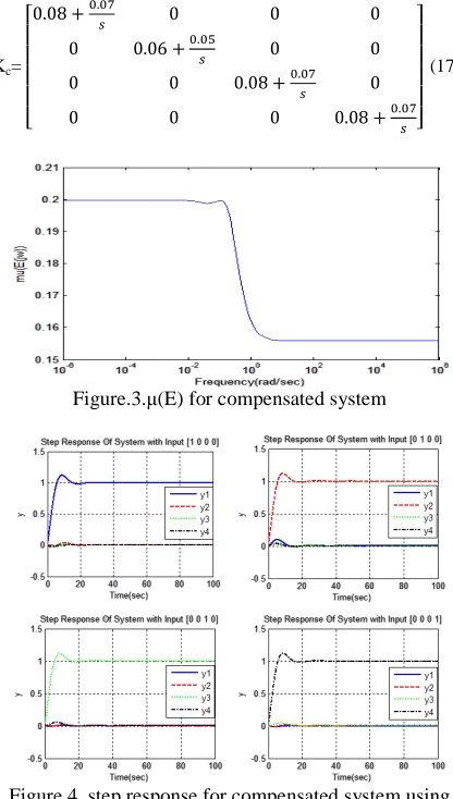
Fig.3 shows that compensated system has the necessary and sufficient condition to form diagonal dominance. Then, to control compensated system, we can use classic control methods of SISO systems. In this example, an independent PI controller is used for every loop. Kc diagonal controller is applied to compensated system.
Kc=
; < < < <
=0.08 +A.AC? 0 0 0
0 0.06 +A.AD? 0 0
0 0 0.08 +A.AC? 0
0 0 0 0.08 +A.AC? FG
G G G H
(17)
Figure.3.µ(E) for compensated system
Figure.4. step response for compensated system using proposed method
Copyright © 2015 IJECCE, All right reserved Step response of closed loop system is shown in fig.4
for specified inputs and compared with diagonal dominance using linear matrix inequalities (LMIs)[28]. The comparison shows that the proposed method with a simple structure eliminates the interaction between channels in a shorter length of time.
Example 2. State space of flight control system of Canard Aircraft is as follows:
RS = T0.60416 0.906240 1.4626 1.170080
0.99104 1.48656 0 U R +
T0.16770 00 0.02290
0 0.1876 0 U V (18)
W = T1 0 00 1 0
0 0 1U R
Its inputs are Longitudinal cyclic pitch control; Lateral cyclic pitch control; Yawn control, respectively. The input signals of canard Aircraft are limited to low frequency which must be paid attention to in design. As the output of reference model is unstable, state feedback compensator model is used. Fig 6. Shows the Nyquist array and Greshgorin bands. Regarding this figure, diagonal non-dominance of system is clear.
Figure.6.Nyquist Array with Gershgorin Bands for uncompensated system
The final proposed compensator to set generalized diagonal dominance is as follows.
Cp=T
−0.9863 2.9073 0.2809
−0.0798 0 −0.1444
0.4353 −10.29 0 U (19)
Figure.7. µ(E) for compensated system
After the generalized diagonal dominance is obtained fig.7, diagonal controller Kc is obtained for compensated system.
Kc=
; < < <
=−0.7 −8.8? 0 0
0 A.? 0
0 0 0.03 +A.8?FG G G H
(20)
The step response closed loop system and that of the presented system by GLMI method[20] are shown in Fig 8 , 9 respectively. LMIs method has not reached a suitable response for this system. GLMI method, as seen in Fig 9, has reduced the interaction in a long time and the compromise of setting time and overshoot has not been done well. This method has more complex calculation than the presented method.
Copyright © 2015 IJECCE, All right reserved Fig.9.step response for compensated system using GLMIs
V.
C
ONCLUSIONIn this paper, regarding the importance of interaction in multivariable systems to reduce the interaction and achieve diagonal dominance, a method was introduced. The setting of system diagonal dominance is done with precompensator which considers the limitation of system performance in specific frequencies. Two examples were simulated to show the efficiency of the proposed method. The designed static precompensators could make the system diagonal dominance in a frequency range. After the design of diagonal controller for compensated system, the results are comparable with the previous ones. The comparison of results shows suitable performance for the proposed method and the simplicity of this method. The method provided can be investigated for the time delay systems.
R
EFERENCES[1] H.H. Rosenbrock, "Design of multivariable control systems using the inverse Nyquist array." Proceedings of the Institution of Electrical Engineers. Vol. 116. No. 11. IET Digital Library, 1969. [2] F.G. Shinskey, "Sistemas de control de procesos." Editorial Mc
Graw Hill (1996).
[3] Q.W. Wang, Decoupling Control, Lecture Notes in Control and Information Sciences, vol. 285, Springer-Verlag, 2003.
[4] B. Ogunnaike, W. Harmor, Process Dynamics, Modelling and
Control, Oxford University Press, 1994
[5] K.J. Åström, K.H. Johansson, Q.W. Wang "Design of decoupled
PI controllers for two-by-two systems." IEE Proceedings-Control Theory and Applications 149.1 (2002): 74-81.
[6] K. Waller, "Decoupling in distillation." AIChE Journal-American Institute of Chemical Engineers 20.3 (1974): 592-594.
[7] P. Nordfeldt, T. Hägglund, "Decoupler and PID controller design of TITO systems." Journal of Process Control 16.9 (2006): 923-936.
[8] S. Tavakoli, I. Griffin, P.J. Fleming, "Tuning of decentralised PI (PID) controllers for TITO processes." Control Engineering Practice 14.9 (2006): 1069-1080.
[9] W.J. Cai, W. Ni, M.J. He, C.Y. Ni, "Normalized decoupling – a new approach for MIMO process control system design." Industrial and Engineering Chemistry Research 47(2008) 7347– 7356.
[10] B.T. Jevtovic, M.R. Matausek, "PID controller design of TITO system based on ideal decoupler." Journal of Process Control 20 (2010) 869–876.
[11] J. Garrido, F. Vázquez, F. Morilla, "An extended approach of inverted decoupling." Journal of Process Control 21 (2011) 55–68.
[12] D. J. Hawkins, "‘Pseudo diagonalisation’and the inverse-Nyquist array method." Proceedings of the Institution of Electrical Engineers. Vol. 119. No. 3. IET Digital Library, 1972.
[13] A. MacFarlane and B. Kouvaritakis, Complex variable methods for
linear multivariable feedback systems, chapter A design Technique for Multivariable Feedback Systems, pp. 247–284, Taylor & Francis Ltd, 1980, Edited by A.G.J Macfarlane.
[14] A.I.Mees,, "Achieving diagonal dominance." Systems & Control Letters 1.3 (1981): 155-158.
[15] N. Munro,"Recent extensions to the inverse Nyquist array design method." Decision and Control, 1985 24th IEEE Conference on. IEEE, 1985.
[16] J. M. Edmunds, "Input and output scaling and reordering for diagonal dominance and block diagonal dominance." IEE Proceedings-Control Theory and Applications 145.6 (1998): 523-530.
[17] Bryant, G.F., Yeung, L.F., Multivariable control system design techniques. Wiley, 1996.
[18] A. Nobakhti, N. Munro, and B. Porter "Evolutionary achievement of diagonal dominance in linear multivariable plants." Electronics Letters 39.1 (2003): 165-166.
[19] S.S.Chughtai and N.Munro, "Diagonal dominance using LMIs." IEE Proceedings-Control Theory and Applications 151.2 (2004): 225-233.
[20] Z. Li, J. Dong, GH. Yang, "Diagonal dominance for flight control systems of canard aircraft in finite frequency range." Control and Decision Conference (CCDC), 2013 25th Chinese. IEEE, 2013. [21] T. Iwasaki and S. Hara. "Generalized KYP lemma: unified
frequency domain inequalities with design applications." Automatic Control, IEEE Transactions on 50.1 (2005): 41-59.
[22] J. Kennedy, R. Eberhart, Particle swarm optimization, in: Proc. IEEE International Conf. on Neural Networks (Perth, Australia), IEEE Service Center, Piscataway, NJ, IV, (1995), pp. 1942–1948. [23] S. Skogestad, I. Postlethwait, Multivariable Feedback
Control-Analysis and Design, Wiley, second Edition,2005. [24] M. P. Newlin and R. S. Smith. "A generalization of the structured
singular value and its application to model validation." Automatic Control, IEEE Transactions on 43.7 (1998): 901-907.
[25] A. Khaki- Sedigh, Analysis and design of multivariable control systems, K. N. Toosi University Press, 2011.
[26] J. M. Maciejowski, Multivariable Feedback Design. Cambridge:
Addison-Wesley, 1989.
[27] X.Z. Nie. the Decoupling Control of Boiler Temperature, Wuhan University of Technology Press, 2007.
[28] W. Liao, J. Zeng, "Multivariable decoupling control of boiler steam temperature system based on diagonal dominance." Computer Science & Education (ICCSE), 2013 8th International Conference on. IEEE, 2013.
A
UTHOR’
SP
ROFILECopyright © 2015 IJECCE, All right reserved