Alam et al. World Journal of Engineering Research and Technology
DESIGN AND IMPLEMENTATION OF AUTOMATED WATER LEVEL
INDICATOR AND MOTOR CONTROLLING USING
MICROCONTROLLER
Md. Shamsul Alam*1, Munirul Alam2, Dr. Mohammad Abdul Alim3
Assistant Programmer Department of ICT Bangladesh.
Article Received on 15/03/2019 Article Revised on 05/04/2019 Article Accepted on 26/04/2019
ABSTRACT
In this writing we are going to show the notion of water level
monitoring and maintaining using electrical conductivity of water.
Here we observe the water level sensing and controlling using
microcontroller in both wired and wireless system. This approach may
help to reduce the home power consumption and as well as overflow of water which causes
wastage. Furthermore, for remote water monitoring system like data loggers, satellite data
transmission systems which can indicate amount of water in the tank. Moreover, now a days
cellular phones are available with high quality graphical and computation power system.
Ultimately, we have given proposal to determine and sense water level universally through an
web and cellular based monitoring service protocol.
KEYWORDS: Indicator, microcontroller, wireless indicator, conductivity, nozzle and water level sensor.
I. INTRODUCTION
In present world sustainability of easily obtainable water resource is dominant issue in many
aspects. So many problems have been arisen due to inefficient use, poor water allocation,
inadequate and integrated water management. Water is such thing which is used in industry,
farmland, plantation and household consumption. Therefore, proper usage and water
monitoring are potential constraints for both internal and external water management system.
In last few eras different monitoring system were introduced to detect water level around the
World Journal of Engineering Research and Technology
WJERT
www.wjert.org
SJIF Impact Factor: 5.218*Corresponding Author Md. Shamsul Alam
world. To utilize water resource it is very important to measure water level for both
government, private sectors and residential usages. Through this way, it would be possible to
find the actual execution of such steps with integration of various controlling activities.
So, automated water controlling system execution makes potential importance in home
applications. The present automated method of water level detection is depicted here and
used the device to make ON and OFF. Generally, in home appliance the very common way of
controlling water level is to start the feed pump at a low level and assume it to reach at higher
level of water inside the tank. It is examined that, this is not rightly supported for adequate
controlling system. Besides this, for monitoring of fluid levels, silos, reservoirs, and dams
etc. are being vastly used by liquid level control system. Usually, this sort of system have
various characteristics like visual multi level of tank, continuous level indication. Automatic
control of pumps and visual & audio alarms at desired levels as user requires can be added in
this prevailing system. Monitoring is very crucial side to have water sustainability at a
desired goal in an automation system. This paper is presented in following ways. i.e. basic
concepts of the system design is discussed in the chapter two. In the next chapter the concept
of PIC16F84A is depicted. This type programmatic approach through microcontroller must
result of an automated water level detecting and controlling system. In the fourth chapter
Design and Implementation part is described. Chapter five is on proposal of monitoring and
controlling the network. The last chapter is involved with the future works and conclusion.
II. BASIC CONCEPTS A. Water Level Indicator
The water level monitoring and controlling system is contained by some basic parts which are
softly aggregated together in our proposed method like LED is used for indication of different
water levels. LED will be lighted with the aggregation of water level sensors. LED is ON if
the sensor senses water and OFF for not sensing water. This is the basic technique to monitor
and control water level.
B. Water Level Sensor
We would like to introduce an water level sensor with some handy materials like resistance,
rubber, iron rod and nozzles etc. Iron and steel are the main elements of a connecting rod
which should be connected with ground. There are at least four nozzles which needed to
at the joint position will act as an insulator. Through the properties of conductivity water,
nozzles and connecting rod get electric connection with the attachment sensors and water.[13]
C. Water Pump Controlling System
To control water pump automatically there is an output pin of microcontroller via a motor
driver circuit. Generally, microcontroller sends two types of signal i.e. positive (+5v) and
ground (0v) signals to the motor driver circuit which causes ON and OFF respectively of the
water pump. Besides a manual switch is used on the motor driver circuit for controlling it
manually which makes the total system more user friendly. Thus we can say that this system
is combination of both manual and automation processes.
D. Microcontroller
A microcontroller is a compact integrated circuit designed to run a specific operation in
a system. A typical microcontroller includes a processor, memory and both input/output
peripherals in a single chip. It is largely used to monitor and display the functions. It costs
low that is why all the time it becomes the first priority to choose among the designers. This
device can be designed for any specific task. As it is a compact IC so hassle to manage so
many external components are not needed for it’s applications. Using this device we can
achieve TVC (Time, cost, visit) reduction idea and it takes low space to work in the system.[3]
E. Others
It is essential to set interface devices between the high power devices and the microcontroller
pins to control these the high power devices like heaters, lights, motor and solenoids. To
switch electricity from miliampere to several thousands of amperes some mechanical relays
sometimes called contactors are used. in this system to adjust high voltage AC current we
should connect a relay circuit must be connected with negative side of the cable of motor. On
the other hand the positive part of the cable should be joined with 220v ac current. So that
electromagnetic relay is used as an electrical amplifier.
III. PIC 16F84A MICROCONTROLLER
PIC is a sequence of microcontrollers of Microchip Technology family. In fact this is the
sequel of PIC1650 which was developed by General Instrument's Microelectronics Division.
It is controlled by software and programmed in the manner to perform tasks. This
used to control peripheral devices and soothing the load from the main CPU. This is the
reason to choose 8-bit PIC 16F84A microcontroller as a main controller of the system.[3]
A. PIC 16F84A Features
It carries 1000 words of program memory which is capable to translate 1024 instructions
The data memory (RAM) contains 68 bytes.[3]
Data EEPROM is 64 bytes
13 I/O pins that are individual direction control
Indirect, direct and relative addressing modes.
B. Memory Organization
Two memory blocks are found in PIC 16F84A. They are 1. program memory and 2. data
memory.[3] To store program generally flash memory is used in PIC 16F84A because this
type of memory has rewriting mode in a large scale which helps to update information. The
another significant thing is the presence of EEPROM for which it does not matter whether the
switch is On or OFF. This causes not to lose flash memory even being switched off. Data
memory has two parts i.e. general purpose registers and special purpose registers where
general purpose registers are used to store data such as integer and floating-point values and
special purpose registers are for holding programs state.
IV. DESIGN AND IMPLEMENTATION
To examine this experiment we have used some devices and machines like water pump and
which is controlled by an water level sensor and these sensors are used to indicate the water
level by sensing. Two tanks have been kept where one is for reserving water, another is for
general purpose. An eight bit microcontroller for automation and most important thing is the
use of MPLAB programming software to write into PIC 16F84A memory,[3] and finally an
A. System Architecture
To make the system more easier microcontroller is been used hence the complexity of circuit
has been reduced and the design has been simple. Here the water level is sensed by an
inverter and input from the sensor unit is taken by a microcontroller. Water pump’s action
(either ON or OFF) is depended on water status of water tank which is related to input
variables. Through a flow chart of whole design is given blow in Fig. 01.
B. Sensor Unit
Water level sensor part is consisted by two portions. One is the sensor in reserve tank and the
other four sensors are attached inside the water tank. It is referred before that nozzles, rod and
rubber etc. are used to have these sensors. Iron and steel are the elements of rod which is
bounded together with a rubber which causes to make electrical connection of nozzles and
rod individually. 22 kΩ resistance is been used due to water conductivity. The principal
operation of the system is nozzle of the sensor is contacted with water and for water
conductivity, rod and nozzle becomes connected. Input of the inverter connects nozzle which
carries the ground signal (0v). On the other hand the input of microcontroller connects the
output of inverter which causes the LEDs ON or OFF.
C. Control Unit
A specific program controls the microcontroller which is related with water pump. A
transistor is used here also. Emitter of the transistor is grounded and collector is joined with
the relay circuit. Relay circuit contains one inductor and one diode for opposing the change of
current flow and sending signal in one direction respectively. Between two cables of motor
pump one is connected with AC 220V as positive voltage and the other one is joined with
relay circuit as negative point.
Different phase of Control unit are as follows:
1) OFF operation
For OFF operation, transistor plays a vital role and it becomes OFF based on the emitter and
collector openness. In this time microcontroller provides 0V to the base of transistor. After
that no ground signal (0V) is passed in the relay circuit. So positive Signal (+5V) is found in
the negative side of motor pump’s cable. For having 220v ac at the one end and positive
signal (+5v) at other side cause the motor pump keeps OFF.
2) ON operation
To make transistor ON two things are related for the operation. First one is collector and
emitter have to be short and the another is to send positive signal (+5v) through
microcontroller. Both motor pump and relay circuit get ground signal (0V) and that is why
the motor pump will be ON where 220v ac at the one end and ground at negative side.
In addition, the current is changed up-to ground to positive signal (+5V) and it’s vice versa
then inductor can endure some resistance. This the reason to use a diode. To control the
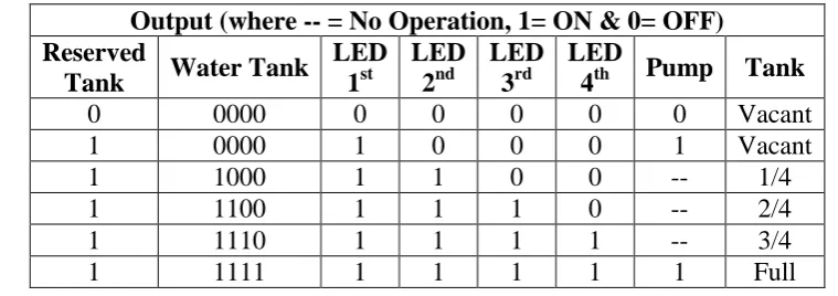
Table Experimental Result.
Output (where -- = No Operation, 1= ON & 0= OFF) Reserved
Tank Water Tank
LED 1st
LED 2nd
LED 3rd
LED
4th Pump Tank
0 0000 0 0 0 0 0 Vacant
1 0000 1 0 0 0 1 Vacant
1 1000 1 1 0 0 -- 1/4
1 1100 1 1 1 0 -- 2/4
1 1110 1 1 1 1 -- 3/4
1 1111 1 1 1 1 1 Full
D. Operation Description and Diagram
To execute the whole system we use some important parts like Crystal Oscillator, PIC
16F84A microcontroller, two capacitors having capacitance 22 pF and 27 pF, water tank,
water level sensor, LED, inverter, transistor, capacitor, inductor, wire and power. Fig. 02
shows the total circuit where all these parts are seen. LEDs are used to monitor water level
from the house (see Table IIor 1 or A) and to detect the water in the reserve tank RA4 pin of
the microcontroller is been used also. For no water in the tank the microcontroller provides a
signal which controls the circuit and keeps switch in OFF mode for while. It starts to sense
the reserve tank again if the timer is kept on. For having the inverted output from the water
source RA0, RA1, RA2 and RA3 pins are used. One side of a crystal oscillator is connected
with two pins of microcontroller and they are Pin 15 and 16. The another end of crystal
oscillator joined with ground through two capacitors 22 pF and 27 pF respectively.
No water in the water tank means four pins RA0, RA1, RA2 and RA3 gets ground signal (0v)
and the resultant is all LEDs are OFF. To indicate the water tank is full RA0 pin senses
positive signal (+5v) and for vacancy pin RA3 senses ground signal. If RA0 senses positive
signal (+5v) then it is indicated that water tank is fully filled with water. On the other hand if
the water tank is vacant then pump becomes ON and the LEDs become OFF. Ground signal
for pins RA0, RA1, RA2 and positive signal (+5v) for pin RA3 means 1/4th of the tank is
filled with water. On the other hand for all pins RA0, RA1, RA2 and RA3 positive signal
(+5v) the LEDs remain ON and means the tank is full of water including the pump should be
OFF.
E. Programming Description
PIC16F84A microcontroller’s assembly language is been used to control the whole process
test. Crystal Oscillator (XTAL) of 4MHZ has worked as external timer. After having the power connection, microcontroller takes input through inverter. Register loads inverted inputs
from pins RA0, RA1, RA2 and RA3 of microcontroller and combination is been checked.
The following ways are found for combination checking.
1. After getting the signal to the first pin of microcontroller then it is loaded to the register.
Next all the pins are checked one after one and the registers are loaded by the signal.
Following the signal combinations an output is been decided and the signal is sent to the
output pin.
2. The total operation is done following a cycle and repeated itself with respect to the input
signals.
V. PROPOSED WATER LEVEL MONITORING NETWORK
Our proposal assures to save a good amount of usable water everyday and control the
wastage a huge amount of water. Besides to make it convenient for monitoring from a remote
place we add an useful wireless automated controlling system. Both monitoring and
controlling through wireless communication processes are described below.
A. Data communication
1) Step 01: Data collection from sensors (WLSi) where (i = 1..3.4.5) and WLS is connected
with USB cable or wireless.
2) Step2: Time duration is fixed to take data. External port is been used to send serialized
data to the controlling server.
3) Step3: Data is sent following bit order and every bit represents sensor activities.
4) Step4: Microcontroller provides data datagram packet and communication can be TCP
and UDP where data is formed following a definite time instance.
B. Data acquisition and representation
Step 01: Data procurement server should tie the particular port that is relegated from data
Water Controll ing System
Web server & Data Acquis
ition
Cell Phone
Step 02: Received Data store in support and process stored information in online application.
Step 03: Data is been changed into XML format. Information could be sending from server
by means of SOAP information passing protocol.
Step 04: Data portrayal ought to be in graphical client interface for clients to monitor and in
this way they ought to have verified access to control microcontroller. If there should be an
occurrence of water level sign, warning message could be incorporated into XML record.
Step5: Data sending technique ought to look after Interface serializability. Additionally, PC
server should bolster multi customer and store obtained information in support that client can
get to database and control microcontroller. What's more, client approval ought to be
incorporated into this area for security viewpoint.
C. Remote communication
Step 01: Design intelligent application programming for remote PC or portable should show
information in table arrangement or in the graphical interface for reconciliation of the remote
water level observing.
Step2: Display the accessible neighborhood associations and the put away remote
associations through the web. Besides, Display distinctive information of remote robotized
controlling framework by various sort (sensors/actuators in one hub, all gadgets in a room, all
gadgets in an loft/production line).
Step3: Display the entire system structure for the support client.
VI. CONCLUSION
Water is a standout amongst the most imperative essential requirements for all living
creatures. In any case, shockingly an enormous measure of water is being squandered by
uncontrolled use. Some other robotized water level observing framework is additionally
offered so far yet the vast majority of the technique has some shortness practically speaking.
We attempted to survive these issues and executed an effective mechanized water level
observing and controlling framework. Our intension of this look into work was to build up an
adaptable, conservative and simple configurable framework which can settle our water losing
issue. We have been utilized an ease PIC 16F84A microcontroller in this framework which is
the key point to decrease cost. We have effectively try the framework in lab and in this
manner proposed an online water level checking and controlling system which adaptability
sort of gadgets. This could have a generous profit by this investigate work for effective
administration of water.
REFERENCES
1. Very Low-Cost Sensing and Communication Using Bidirectional LEDs, P. Dietz, W.
Yerazunis, D. Leigh, UbiComp Proceedings, 2003; 2864: 175-191.
2. www.exploreembedded.com/wiki/Category:LPC1768_Tutorials.
3. www.microchip.com, Microcontroller chip Technology, PIC16F84A Datasheet, 2001.
4. Low-Cost Surface Mount LED Gas Sensor, Roderick L. Shepherd, William S. Yerazunis
and Senior Member, IEEE King Tong Lau and Dermot Diamond, Sensors-00997, 2005.
5. Microcontroller Based Electric Expansion Valve Controller for Air Conditioning System,
T. S. Aye, and Z M. Lwin, World Academy of Science, Engineering and Technology,
2008.
6. R.E. Shaffer, S.L. Rose-Pehrsson, R.A. McGill, A comparison study of chemical sensor
array pattern recognition algorithms, Anal. Chim. Acta, 1999; 384: 305–317.
7. E.J. Cho and F.V. Bright, Integrated chemical sensor array platform based on light
emitting diode, xerogel-derived sensor elements, and high-speed pin printing, Analytica
Chimica Acta, 2002; 470: 101-110.
8. An environment for runtime power monitoring of wireless sensor network platforms,
Milenkovic, A., Milenkovic, M., Jovanov, E., Hite, D., and Raskovic, D. Proc. of SSST,
2005; 05: 406–410.
9. Monitoring of headspace total volatile basic nitrogen from selected fish species using
reflectance spectroscopic measurements of pH sensitive filmsi, L. Byrne, K.T. Lau, and
D. Diamond, The Analyst, 2002; 127: 1338-1341.
10.Microcontroller Based Automated Water Level Sensing and Controlling; Ajith Kumar,
Bharathi, Inbaveni, Dinesh Kumar, S Siva Subramanian, International Journal of
Advanced Research in Electrical, Electronics and Instrumentation Engineering, Special
Issue 1, March 2016; 5.
11.Automatic Water Level Indicator, Oyndrila Roy , Aranyak Roy, Dr.Debasis Roy;
International Journal of Emerging Trends in Engineering and Development, March 2016;
6(2).
12.Design and Development of ARM Cortex LPC1768 Based Water Level Management
Innovative Research in Science, Engineering and Technology, Visit: www.ijirset.com,
October 2017; 6(10).
13.A Microcontroller-Based Monitoring System for Batch Tea Dryer, M. Javanmard, K.A.
Abbas, F. Arvin, CCSE Journal of Agricultural Science, December 2009; 1(2).
14.Microcontroller Based Automated Water Level Sensing and Controlling: Design and
Implementation Issue; S. M. Khaled Reza, Shah Ahsanuzzaman Md. Tariq, S.M. Mohsin
Reza Proceedings of the World Congress on Engineering and Computer Science 2010