GSJ: Volume 7, Issue 9, September 2019, Online: ISSN 2320-9186
www.globalscientificjournal.com
I
MPLEMENTATION OF BUILDING INFORMATION MODELING TOOLS FOR
C
ONSTRUCTION
MANAGEMENT
O
PTIMIZATION
Engr. GhufranUllah, Engr. Mohib Ur Rahman, Engr. Muhammad Tayyib, Engr. NayabKaleem, Engr. Syed Shujaat
Ali Shah and Engr. Faisal Zaman
Author Engr. GhufranUllah is currently pursuing masters degree program in construction management in Iqra National University Peshawar, Pakistan, PH-+92323-9227378 E-mail: [email protected]
Co-Author Engr. Mohib Ur Rahman is currently pursuing master’s degree program in construction engineering and management inIqra National University Pesha-war, Pakistan. E-mail: [email protected]
Co-Author Engr. Mohammad Tayyib is currently pursuing master’s degree program in construction management in Iqra National University Peshawar, Pakistan, E-mail: [email protected]
Co-Authors Engr. Nayabkaleem is currently working as civil engineer in Frontier Works Organization, Pakistan, E-mail: [email protected]
Co-Author Engr. Faisal Zaman is currently pursuing masters degree program in construction management in Iqra National University Peshawar, Pakistan, E-mail:
Co-Author Engr. Syed Shujaat Ali Shah is Lecturare at Iqra National University Peshawar, Pakistan, E-mail: [email protected] Supervisor Engr. Syed Shujaat Ali Shah is Lecturare at Iqra National University Peshawar, Pakistan, E-mail: [email protected]
KeyWords
Building Information Modeling, Autodesk Revit, n-D Modeling, Construction Management, BIM Tools, Optimization, Light Analysis, Quantity Takeoff, Energy Analysis, Solar Analysis
ABSTRACT
During the design stage a construction project is exposed to numerous risks including clashes between Architectural, Structural and MEP designs and poor estimation of quantities and costs. These risks lead to delayed completion and over run costs. In construction project main stakeholders, the contractor and the client wants the project to take least time with cost as less as possible. Building information modeling (BIM) is a solution to these problems which not only detects the clashes but also gives a reliable platform for solution of these clashes be-fore the project execution. Moreover BIM also automatically generates quantities and costs accurately. Along with it, different models can be prepared during the planning phase, which gives detailed visualizations of the project at the very start of the project and all the stake-holders can have a good idea of what the end product would look like.
INTRODUCTION
Building Information Modeling can be defined as “An integrated digital process providing coordinated, reliable information about a project throughout all phases, from design through construction and into operation” *1+. BIM is one of the most promising develop-ments in the Construction industry. It works on the principle of “Build Digitally First” i.e. by simulation of a project virtually before on-ground construction. BIM is an intelligent system which contains information spread over a number of dimensions including in-formation about the design/geometry of the structure and supporting inin-formation related to the material of the structural members, construction practices, quantity of works, schedule of works, procurement activities etc. All this information helps in making the exe-cution of a projectsmoother and ensures completion of the project on time and within the allocated budget *2+.
Building Information Modeling has a wide area of application. It has been successfully applied by stakeholders/ professionals from different backgrounds for the optimization of their efficiency and profit. Architects designers use it for the visualization of the struc-ture, designers make use of the tools provided by BIM to optimize their design by conducting a Forensic Analysis and make sure it is coherent with the architect’s plan for the structure, consultants make use of the tools offered by BIM for the monitoring of the works on site and making sure that the work is progressing as per schedule and the required quality is being attained, contractors use it to keep a track of their works and for billing process, and clients use it for the calculation of quantity of works, budgetary require-ments calculations and tendering process *3+. The biggest advantage of BIM is the reduction in chances of miscommunication be-tween stakeholders of a project resulting in reduced chances of clashes bebe-tween stakeholders *2,4+.
Building Information modeling brings about revolutionary changes in the area of graphic modeling. By storing and managing building information as databases, building information modeling solutions can capture, manage, and present data in ways that are appropri-ate for the building team member using that data. As all the data and information is stored in the data base, and afterward changes in the data can also occur and can be carries out during the whole life cycle of the project. It can also be helpful after the completion of project for the maintenance and extension purposes. BIM creates a link between the building components which can be used much beyond as can be done in object level information in traditional object oriented based CAD. This allows the amendments and clash removal during the design period before the execution of project *6+. It doesn’t only bears the components of building but also linked them in a proper relationship to carry out a detailed analysis of the clashes among the different components of the project. The relationships are created by the user and thus he can also understand them in a proper manner and carry out the further opera-tions to remove the clashes and he can also monitor the ongoing project along with the prescribed schedule by the user *3,7+.
AUTODESK RIVET MODELING
department to the execution department, which then can generate the bill of quantities (BOQ’s) in the required format by using the standalone application *12,13+.
METHODOLOGY
Building of DHQ Mardan was modeled for complete understanding and analysis of Building Information and Modeling tool. The building was three storeys and covered area was more than 4.5 square feet. All the drawings collected from respective authorities were in AutoCad 2-D. Autodesk Revit was used for 3-D modeling of architechtural, structural and MEP models moreover it was also used for light analysis and calculation of heating and cooling loads. Autodesk Navisworks was used for clash detection and mitigation. For calculation of quantities autodesk quantity takeoff was used. The overall methodology adopted is given in figure 1.
Modeling Process
Following steps were followed for complete modeling and analysis of building in Autdesk Revit.
Architectural Model
Architectural model provides a virtual manifestation of the structure to be built and also provides a reference for the development of other models including structural, and MEP models.
Grid Establishment
Material Definition and Families
This is followed by the definition of each component as per directions and specifications of the manufacturer. A complete package of data that has both geometric and material properties of a component of the building and can be used in Autodesk Revit is called a Family. These families need to be defined before the components can be placed in Revit to develop the model.
Frame Structure
Frame structure was made in the first stage which provided the basic skeleton for the other members to be placed. Frame structure includes Beams, Columns, Footings and Slabs. A special attention is paid to make sure the correct placement of the frame members. Dimensions of the members are made sure to be correct. This is merely a hollow structure which provides the body for the place-ment of reinforceplace-ment in them.
Floors, Slabs and Roof
Floors are added to the frame structure by first making out the levels of the structure. These levels are a form of grids which provide reference lines for jobs such as specification of points in space for the addition of floors and detail addition. For the addition of slab in the model it is necessary that we define the properties of the slab first and then select the boundaries by which the slab in bound, Revit will automatically draw out the slab inside the indicated boundaries.
Walls and Shafts
Walls were incorporated in the model as per specifications and drawings. For the placement of walls in the interior and exterior of the building, grids and levels came in handy. We added walls to only a single floor and making use of the levels, copied them to other floors.
Doors, Windows and Stairs
Before the installation of doors and windows it was made sure that the details that are required in walls like openings etc. were al-ready done. After the openings required for doors have been placed it was just a drag and drop task. For the windows, we first edited the families to make out the required types of windows and windows were dragged and dropped at the required locations. Stairs are made by first defining the start and stop levels, then defining the properties of riser, tread and width of the stairs. Revit automatically sets the number of stairs and draws them out.
Structural Model
The structural model includes all the structural information about the project and is used for the structural analysis of the project to determine the adequacy of the proposed model. This structural model is made by linking a new structural project to the already pre-pared architectural model. In the next step, grids and levels are copied to the new structural model to get a reference for the work to be done in the structure model. This is followed by addition and specification of various members and their properties. Structural model requires placing of each and every member again but this time the family is modified to incorporate structural components like rebars.
Foundations
The structural model is started by the definition of the properties of the structural foundation. After the foundation has been de-fined, rebars are placed inside the defined foundation structure as per design specification and drawings. The Area reinforcement tool is used to place rebars in such members of the structure.
Structural Framing
By making use of the reference points and lines extracted from the architectural model, structural framing is modeled as per design specifications. The structural model includes structural columns, beams and footings.
Slabs and Roof
properties and structural families are used to enable the model to accommodate structural rebars. These members are easy to place in the model as we only need to define the boundaries and Revit does the job.
Structural Reinforcement
For the placement of the structural rebars, each component must be cut via a section and the bars’ properties defined and then placed. Area reinforcement in members like slabs, footings and wall is a little bit easy to place as the need is only to define the bar properties like size, length and spacing. Then the boundaries and members are selected to place the bars and Revit does the job. Here there is a need to revise and recheck the rebars for any incorrect placing. One of the downfalls is that such reinforcement is very difficult to modify after placement.
MEP Model
In the first stage all the openings were provided in the architectural model for the entry and exit of HVAC, Piping etc. The revised model was then imported to the MEP software and work was started on the development of MEP model by defining and placing the components.
Plumbing Model
Plumbing model was developed by defining a separate plumbing template and then importing and linking the structural and archi-tectural models. This provided the space required for the definition of the plumbing model. As per drawings, all the members of the plumbing model were added to complete the model as whole.
Electrical and HVAC Model
HVAC and Electrical models were made as per the drawings and specifications. HVAC model required an elaborate revision of the architectural model for the definition of openings for the air ducts. The openings were defined as per the requirements by ducts and after the definition of openings ducts were laid out. The central system was placed on the roof top and ducts were passed through-out the building which circulated the air from the central system to the whole building. For the detailing of the electrical plan, the structure was divided into different portions and each portion was then again divided into various sub-portions. All electrical points were connected and the electrical wiring was done inside the slab of each floor. Electrical components were placed at their exact locations as per drawings.
Clash Detection and Resolution
After modeling clashed occurring were detected and removed by mutual coordination.
4-D Simulation and Scheduling
Scheduling was performed using Primavera P6 and Autodesk Navisworks. For the generation of timeline of the project all of the ac-tivities were inserted in Primavera P6 and scheduling was performed to determine the critical path for the construction acac-tivities. A .csv file is generated and in Primavera P6 and it is then imported into Autodesk Navisworks. Separate sets of components of each model are made and linked with the respective timeline of the activities in the .csv file and 4D simulation is run.
5-D Quantity Takeoff
4.8 6D Light Analysis
Light analysis of the structure was performed using Autodesk green building studio.The model was imported into the software and complete data relating to the location of the model (Mardan,kpk) was put into thesoftware and analysis was run.
4.9 6D Heat and Cooling Loads Analysis
Light analysis of the structure was performed using Autodesk green building studio. The model was imported into the software and complete data relating to the location of the model (Mardan,Kpk) was put into the software, rooms and spaces were selected and analysis was run.
RESULTS
Complete analysis and modeling of building using Revit and other supporting software showed that BIM is essential practice for reli-able modeling and solving the issues before they actually happen. Following data was generated by these software.
Errors in Drawings
There were some errors in drawings of DHQ Mardan in which at some HVAC ducts and plumbing pipes were passing through the structural beams. There was also a problem in elevation height of one of the cooling equipment of HVAC on top of roof due to which it was resting on beams instead of roof causing its ducts levels to be inappropriate and misplaced which were adjusted accordingly after discussing with the advisor .Due to lack of collaboration between the architect and the engineer there were numerous ambi-guities and inaccuracies in the architectural and structural drawings. At times the location of beams and columns in structural draw-ings would differ from that in architectural drawdraw-ings. BIM tools would have provided a robust collaboration between the two team members and the difference in their drawings would have been negligible or none at all.
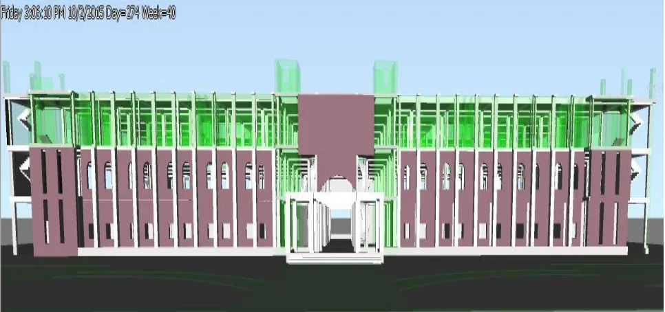
3-D model
Figure 1 3-D Model of building
4-D Simulation
Each item was linked with respect activity with start and completion date. The navisworks generates a 4-D plan having time as 4th dimension. With passing time the construction stages were included as completed activities. The overall progress was generated in a form of realistic images and animated video. Figure 2 shows a gilpmse of 4-D simulation at execution phase. The main advantage is that work can be monitored easily as we have a 3-D model matching with actual work that has been done till that time. It can also be used to determine schedule confilt if some activities goes off schedule which is equally helpful for forcasting future problems as a result.
5-D Quantity Takeoff
For the purpose of quantity take off a number of softwares are available. The Revit model could be exported to these softwares and accordingly the quantities of the materials could be known .In our project the total amount of concrete was determined using the Autodesk Navisworks quantification workbook tools. Quantity of reinforcement was calculated using Sofistik. A schedule of materials was prepared in the Autodesk Revit showing the number of different components used in the structure. Quantities calculated by Revit models were almost same as actual quantities being carried out for execution purposes.
Autodesk Revit was used to determine the number of items used in the structure like washroom items, cupboards, windows, doors, furniture etc. Material details were generated by using Autodesk Revit and includes details of items like plaster, paint, finishing etc..
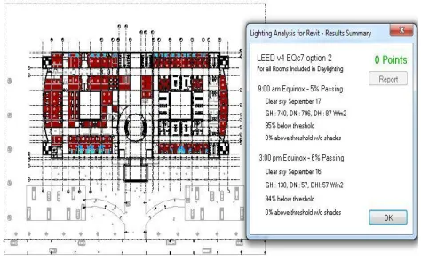
Light Analysis
The results of light analysis are shown in figure 2. The results indicate the penetration of natural light inside the building in units of lux. Light analysis gave us the requirements and the extent/condition of lighting (natural or artificial) in the structure.These results can be used to decide about the requirements of artificial lighting to be provided in the finishing stages.
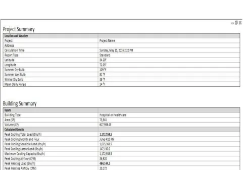
Heat and Cooling Load Calculation
The summarized calculation of the building for heat and cooling loads is shown below. The total requirement of cooling with respect to peak hot day of the year is shown in figure 4.
CONCLUSION
After application of BIM technology to a real life model, we came to a conclusion that this technology must be adopted by the con-struction industry to increase its efficiency and reduce losses. Development of high quality and precision drawings showing great amount of detail including material details.In BIM model making the sections and elevations is just a click of mouse away. The-se The-sections and elevations are as per the plans and the The-separate human effort induced is reduced while the uThe-se of BIM model.Saving of precious time during planning and design phase of the project due to intelligent process.A proactive approach to preempt any possible clash or errors that may occur during the course of the project saving time and money.Scheduling can be done with ease and confidence of making sure that all construction activities are addedBIM makes possible the optimization and revision of design of structures.The cost estimation is done manually and they are prone to a lot of errors, since a lot of things could be missed out in the manual estimation however BIM provides an accurate quantity take offs form the model prepared.Removal of miscommunica-tion and misunderstanding between the stakeholders resulting in the reduced number of conflicts during the course of the project.
Acknowledgment
References
[1] Kovalenko, A. A. (2019). Integration of BIM in construction education. BIM in Construction & Architecture. doi: 10.23968/bimac.2019.038
[2] Luo, P., & Tang, J. (2015). Research on Collaborative Design Practice of REVIT Based on BIM. Applied Mechanics and Materials, 713-715, 2552–2555. doi: 10.4028/www.scientific.net/amm.713-715.2552
[3] Al-Gendy, M., Osman, H., & Taha, M. (2012). BIM-Enabled Condition Assessment Tool for Building Maintenance Using Revit Architecture. Research, Development and Practice in Structural Engineering and Construction. doi: 10.3850/978-981-08-7920-4_fam-5-0400
[4] Huang, C. (2017). Application of BIM Technology Based on Autodesk Revit in Construction and Installation Engineering. Proceedings of the 2017 3rd International Conference on Economics, Social Science, Arts, Education and Management Engineering (ESSAEME 2017). doi: 10.2991/essaeme-17.2017.262
[5] Farzaneh, A., Monfet, D., & Forgues, D. (2019). Review of using Building Information Modeling for building energy modeling during the design process. Journal of Building Engineering, 23, 127–135. doi: 10.1016/j.jobe.2019.01.029
[6] Burry, M. (2015). BIM and MetaBIM: Design Narrative and Modeling Building Information. Building Information Modeling, 349–362. doi: 10.1002/9781119174752.ch26
[7] Bolotin, S. A. (2019). Scheduling of complex development using Revit and Microsoft Project. BIM in Construction & Architecture. doi: 10.23968/bimac.2019.009 [8] Eastman, C., Teicholz, P., Sacks, R., & Liston, K. (2008). BIM Handbook. doi: 10.1002/9780470261309
[9] BIM Data: The “I” in BIM. (2019). BIM Content Development, 121–139. doi: 10.1002/9781119574316.ch9
[10] Kota, S., Haberl, J. S., Clayton, M. J., & Yan, W. (2014). Building Information Modeling (BIM)-based daylighting simulation and analysis. Energy and Buildings, 81, 391–403. doi: 10.1016/j.enbuild.2014.06.043
[11] Cheng, Y. M., & Chen, J. Y. (2013). Application of BIM on Quantity Estimate for Reinforced Concrete. Applied Mechanics and Materials, 357-360, 2402–2405. doi: 10.4028/www.scientific.net/amm.357-360.2402
[12] Cheng, Y.-M. (2018). Application of BIM on Documenting Construction Defects. International Journal of Engineering and Technology, 9(5), 392–397. doi: 10.7763/ijet.2017.v9.1005