ISSN (e): 2250-3021, ISSN (p): 2278-8719
Vol. 07, Issue 07 (July. 2017), ||V1|| PP 61-65
Optimization of process parameters of Material Removal Rate in
Micro hole Machining by Die sinker EDM
*
U Ashok kumar
1, P.Laxminarayana
21(Research Scholar, Dept. of Mech. Engg, University College of Engg, Osmania University, Hyderabad, INDIA) 2
(Professor, Dept. of Mech. Engg, University College of Engg, Osmania University, Hyderabad, INDIA) Corresponding Author: U Ashok kumar
Abstract:
The present work deals with optimization of material removal rate in micro holes machining of SS316 sheet materials using copper electrode of diameter 300µm, 500µm, 900µm on Die sinker Electrical discharge machining with input parameters of current (I), Time –on (T-on), Time –off (T-off) Experiment were conducted by taguchi L9 orthogonal Array design has been studied.Keywords:
Die Sinker EDM, Material removal rate, Micro holes, Taguchi L9 OA
--- --- Date of Submission: 21-07-2017 Date of acceptance: 08-08-2017 ---
---I.
INTRODUCTION
EDM is a non-traditional machining process where hard materials are machined to get proper machining shape as per design specification in industrial sectors of moulds, dies, automotive, aerospace and surgical instruments. The working mechanism of EDM is based on the thermo spark energy where it is created between the electrode and the work piece, immersed in dielectric fluid with the way of electric current and separated by a small gap called spark gap. Pulsed arc discharges occur in this gap filled with a dielectric liquid like hydrocarbon oil or de-ionized (demineralized) water. The technique of material removal with EDM is still arguable. This is because ignition of electrical discharges in a liquid filled gap, when applying EDM, is mostly interpreted as ion action identical as found by physical research of discharges in air or in vacuum. The reduced spark gap results that the applied voltage is high enough to ionize the dielectric fluid. The electrode and work piece are separated by the short duration pulses which are generated in liquid dielectric gap. The spark is generated at the smallest inter electrode gap. The erosive effect of discharges removes the material from the tool and the work piece It flushes out the removed material during machining and cools the electrode from heating. The erosion of work piece material uses electrical energy and converts them into the thermal energy through a series of electrical discharges. The material is removed by partial vaporization or melting. The removed debris in molten state re-soldified and flushes out with help of dielectric fluid. The thermal energy generates plasma between tool and work material having temperature range 8000˚C to 12000˚C and high as 20000˚C. When the DC supply is switch off then plasma channel breaks down results in reduction in temperatures [6] In EDM operation, the material removal rate is less as compare to conventional machining. The amount of material removal rate is dependent upon the amount of pulsed current in each discharge, frequency of the discharge, dielectric flushing condition, and electrode and work piece material. Surface finish is an important factor for the work-piece. It becomes more vital so as to produce a better surface when hard materials are machined, requiring no subsequent polishing with accurate spark gap
II.
EXPERIMENTAL
METHODOLOGY
Here, the equipment used to perform EDM experiments and material removal rate analyses are described, and also the properties and dimensions of work piece and tool electrode have been mentioned.
2.1 EDM Equipment Machine:
Die sinker EDM ACRO Machine is used for conducting experiments
2.2 Materials required
Stainless Steel 316 is secondly most common used austenitic steel. The work piece materials were stainless steel 316 and copper electrode of diameters 300µm, 500µm, 900µm and chemical combination of workpiece & electrode are list in Table.1&Table.2
Table 1. Material Chemical Composition of AISI316
Table 2. Material Chemical Composition of Copper electrode
Table 3. Experimental machining condition for micro-hole machining on SS 316
III.
DESIGN
OF
EXPERIMENTS
An efficient experimental design helps to optimize the process and determine factors that influence the variability.Taguchi’s orthogonal arrays (OA) provide a set of well-balanced experiments which gives much reduced variance for the experiment with optimum set of control parameters. Minitab 17 software was used to make the design of experiments (DOE). Based on the degree of freedom of control parameters, an L9 Taguchi OA was selected for the present experimental work. Three input parameters, ie, current (amp), pulse-ON time (μs) and pulse-OFF time (μs) each having three levels was used to create the orthogonal array were used in Table4..
Table 4.Machining Parameters used in the Experiment
Factors Level 1 Level 2 Level 3
Current (I) 0.2 0.4 0.8
T-on 6 8 10
T-off 4 6 8
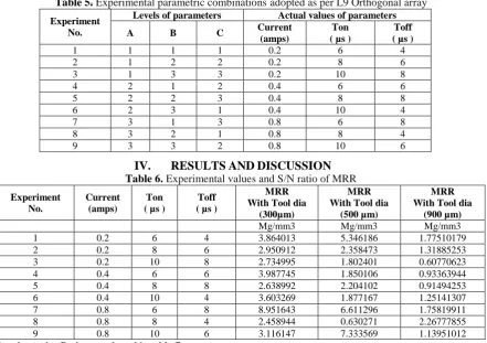
Table 5 shows for each combination of the factor levels with nine experiments are performed and the machining time is noted in each case
Table 5. Experimental parametric combinationsadopted as per L9 Orthogonal array
Experiment No.
Levels of parameters Actual values of parameters
A B C Current
(amps)
Ton ( µs )
Toff ( µs )
1 1 1 1 0.2 6 4
2 1 2 2 0.2 8 6
3 1 3 3 0.2 10 8
4 2 1 2 0.4 6 6
5 2 2 3 0.4 8 8
6 2 3 1 0.4 10 4
7 3 1 3 0.8 6 8
8 3 2 1 0.8 8 4
9 3 3 2 0.8 10 6
IV.
RESULTS
AND
DISCUSSION
Table 6. Experimental values and S/N ratio of MRR
Element Cu Zn Al Bi Pb
% 99.90 0.057 0.15 0.0011 0.0008
Input Parameters Description
Work piece SS316
Electrode 300,500,900 μm
Dielectric fluid EDM OIL
Polarity Positive (work piece ‘+ve’ and tool ‘-ve’)
Current 0.2,0.4,0.8 amps
T-on 6, 8, 10
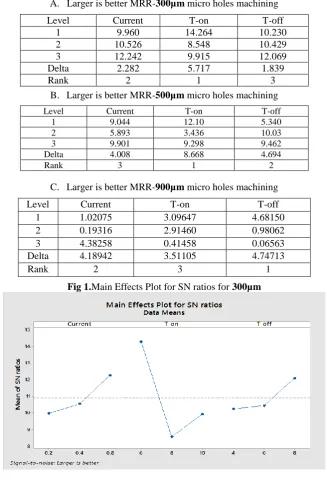
Table 7.Response Table for Signal to Noise Ratios of 300µm
,5
00µm, 9
00µmmicro holes A. Larger is better MRR-300µm micro holes machiningB. Larger is better MRR-500µm micro holes machining
C. Larger is better MRR-900µm micro holes machining
Fig 1.Main Effects Plot for SN ratios for 300µm
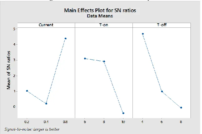
Fig 2.Main Effects Plot for SN ratios 500µm
Level Current T-on T-off
1 9.960 14.264 10.230
2 10.526 8.548 10.429
3 12.242 9.915 12.069
Delta 2.282 5.717 1.839
Rank 2 1 3
Level Current T-on T-off
1 9.044 12.10 5.340
2 5.893 3.436 10.03
3 9.901 9.298 9.462
Delta 4.008 8.668 4.694
Rank 3 1 2
Level Current T-on T-off
1 1.02075 3.09647 4.68150
2 0.19316 2.91460 0.98062
3 4.38258 0.41458 0.06563
Delta 4.18942 3.51105 4.74713
Fig 3.Main Effects Plot for SN ratios 900µm
From Fig 1. The combination process parameter is A3B1C3 for 300µm From Fig 2. The combination process parameter is A3B1C2 for 500µm From Fig 3. The combination process parameter is A3B1C1 for 900µm
Confirmation Test
Once the optimal combination of process parameters and their levels was obtained, the final step was to verify the estimated result against experimental value. It may be noted that if the optimal combination of proceee parameters and their levels were not coincidently match with one of the experiments in the OA, then confirmation test is required
yopt = m + (mAopt-m) + (mBopt-m) + (mCopt-m)
Where m: average performance Y optimum condition
for 500µm micro hole machining of MRR =6.63831 mg/mm3 for 900µm micro hole machining of MRR =2.31624 mg/mm3
V.
CONCLUSION
Results obtained from the Optimum machining conditions MRR for micro holes machining study following can be concluded:
Table 8.From the Confirmation test
MRR Optimum machining conditions for MRR of 300µm ,500µm, 900µm micro holes
Prediction Experiment Difference %
REFERENCES
[1]. Kansal HK, Singh S, Kumar P (2005) Parametric optimization of powder mixed electrical discharge machining by response surface methodology. J Mater Process Technol 169(3):427–436
[2]. Singh SK, Kumar N, Kumar A (2014) Experimental investigations of EDM to optimize surface
roughness of titanium alloy (Ti-6AL-4V) through Taguchi’s technique of design of experiments. Int J Curr Eng Technol.
[3]. Swapan B, Vijay B, Nagahanumaiah C, Purid A B (2014), “Surface Texture and Elemental
Characterization of High Aspect Ratio Blind Micro Holes on Different Materials in Micro EDM”, Procedia Materials Science 3rd International Conference on Materials Processing and Characterisation (ICMPC 2014), Vol. 6, pp. 304 – 309
[4]. Pradhan D, and Jayswal S C (2011),“Behavior of Copper and Aluminum Electrodes on EDM of EN8
-Alloy Steel”,International Journal of Engineering, Science & Technology, Vol. 3, No. 7, pp.5492–5499.
[5]. Mohamad A B et al. (2012), “Optimization of EDM Process Parameters Using Taguchi Method”,
International Conference on Applications and Design in Mechanical Engineering
[6]. U. Ashok Kumar, P. Laxminarayana, N. Aravindan (2017) “Surface morphology on micro machined
surfaces of AISI 316 by Die Sinker EDM”, Materials Today: Proceedings Volume 4, Issue 2, Part A, Pages 95-4136 (2017) https://doi.org/10.1016/j.matpr.2017.01.149
[7]. Zhang L, Tong H, Li Y (2015) Precision machining of micro tool electrodes in micro EDM for drilling