QFT Based Controller Design of Thyristor-Controlled Phase
Shifter for Power System Stability Enhancement
Ki Sun Han
1, Moon Gyu Jeong
1, Jeong Phil Lee
21(Power Transmission Laboratory, Korea Electric Power Corporation Research Institute, Korea) 2(Subdivision of New &Renewable Electricity, Kyungnam College of Inform.& Tech., Korea)
ABSTRACT:
This paper presents the automatic design method for a thyristor-controlled phase shifter (TCPS) controller based on quantitative feedback theory (QFT) to improve power system stability in spite of system uncertainties and various disturbances. A genetic algorithm (GA) in a loop shaping state of QFT design has been used to design the TCPS controller satisfying all QFT bounds without repetition of a manual try and error. The proposed performance index in GA has been composed of the QFT bounds and the damping ratio. To verify control performance of the proposed TCPS controller based on QFT using GA, the closed loop eigenvalue and the damping of power system have been analyzed and nonlinear simulations for a single machine infinite bus system have been performed under various disturbances for various operating conditions. The control characteristics of the proposed TCPS controller have been compared with that of the conventional power system stabilizer (PSS) and conventional TCPC controller. The simulation results show that the proposed TCPS controller provided better dynamic responses in comparison with the conventional PSS and TCPS controller.Keywords:
Quantitative feedback theory(QFT), genetic algorithm(GA), thyristor-controlled phase shifter (TCPS), robust control, power system stabilizer (PSS).I.
INTRODUCTION
The complicatedly interconnected power systems have a small signal oscillatory instability characteristics caused by insufficient natural damping in the system. A power system stabilizer (PSS) has been widely utilized to damp low frequency oscillation and to improve small signal stability through the supplementary excitation control of a generator [1-4]. However, a PSS may cause great variations in the voltage profile, may result in leading power factor and may not be able to suppress oscillation resulting from severe disturbance [5]. With the recent advances in power electronics technology, the flexible AC transmission system (FACTS) devices have been installed to enhance power system stability, such as thyristor-controlled series capacitor (TCSC)[6], static var compensator (SVC)[7], thyristor-controlled phase shifter (TCPS)[8], unified power flow controller (UPFC) [9] and static synchronous compensator (STATCOM) [10]. The application of supplementary controllers for the FACTS devices which use reliable and high speed power electronic devices can considerably improve system damping and can also improve the system voltage profile, which is advantageous over a PSS [5]. As one of the FACTS devices, several approaches for a TCPS have been applied to damping controller design in power system [11-18]. The TCPS provides an alternative to the conventional PSS in suppressing power system oscillations and is of particular importance to the power system where a PSS cannot be properly installed for reasons such as the system voltage profile, the unsuitability of the generator and so on [12].
II.
POWER
SYSTEM
MODEL
2.1 Generator and exciter
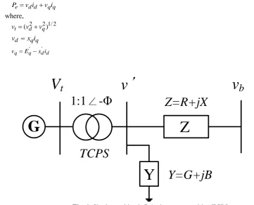
Fig. 1 shows the single machine infinite bus power system which has the TCPS and local load admittance Y in a generator bus, and transmission line impedance Z [8][15]. The generator with the IEEE Type-ST1 excitation system is modeled by four first-order nonlinear differential equations as following equations [3].
))/M D(ω P P ω dt d e
m 1
(1) ) (ω ω δ dt d
b 1
(2)
' ')/T E ')i x (x (E ' E dt d d q d d d fd
q 0 (3)
A fd E t ref A
fd (K (V v u ) E )/T
E dt
d (4)
whereis the rotor speed, bis the synchronous speed and
the rotor angle.Mis inertia constant, D is damping coefficient, Tdo' is the open circuit field time constant andEq'is internal voltage.Efdis the field voltage,vtis terminal voltage and uEis PSS control input.The output electric power equation of generator is given by
q q d d e v i v i
P (5)
where, 2 / 1 2 2 )
( d q
t v v
v (6)
q q d x i
v (7)
d d q
q E x i
v ' ' (8)
G
Z
Y
1:1
∠
-Φ
Z=R+jX
Y=G+jB
V
t
v
’
v
b
TCPS
Fig. 1. Single machine infinite bus system with a TCPS
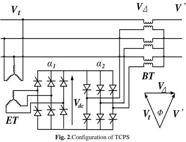
2.2 TCPS model
Fig. 2 shows the configuration of a TCPS [11][13][15]. The basic function of a TCPS is to control transmission line power flow through the modulation of the phase angle difference between the two sides of the transmission line voltage. The voltage at the end bus of TCPS v'is phase shifted with respect to the input voltage
t
v by angle as shown in Fig. 2[15].
The TCPS in Fig. 1 has a ratio of 1:1. The real power flow is obtained by
) sin( ' X v E
where is phase shift angle of the TCPS. The TCPS can control the relative phase angle between the system voltage by adjusting the angle .The phase shift angle of the TCPS, , can be modeled by the first order transfer function and can be written as following equation [8][17].
S TCPS ref
S( u ) )/T
(K dt
d (10)
where refis the reference angle, and TSandKSare the gain and time constant of the TCPS respectively.
V
VΔ
V
’
BT
V
dcα
1α
2V
V
’
V
Δ
Φ
ET
t
t
Fig. 2.Configuration of TCPS 2.3 Linearized model
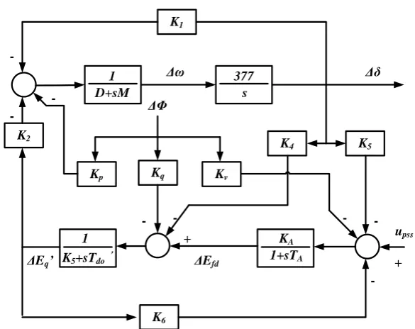
To design QFT based controller, the linearized model around a nominal operating point is needed. The detail procedure is in [8]. The linearized equation to nonlinear differential equations such as (1)~(4) and (10) including the generator, excitation system and TCPS can be expressed by
u B x A x
(11)
where,
A A v A A A A A A do q do do do p bT
T
K
K
T
T
K
K
T
K
K
T
K
T
T
K
T
K
M
K
M
K
M
D
M
K
A
1
0
0
0
0
1
0
'
'
1
'
0
'
0
0
0
0
0
6 5 3 4 2 1
, S S T K B 0 0 0 0 x [ ,
,
E
q'
,Efd,]T, u[uTCPS].x
andu are the state and control vector respectively. A and B are constant matrices which depend on system parameters and the operating point. The parametersK1~K6,Kp,Kq andKv are computed in operating condition.
K1
D+sM 1
s 377
Kq
Kp Kv
K4 K5
K2
K5+sTdo ’
1
1+sTA
KA
K6
+
--
--
-+
-ΔΦ
Δω Δδ
upss
ΔEfd
ΔEq’
Fig. 3.Block diagram of the linearized power system model
III.
DESIGN
OF
TCPS
CONTROLLER
BASED
ON
QFT
USING
GA
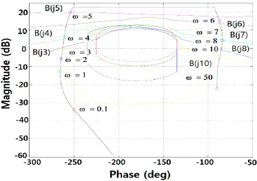
3.1 QFT overview [19]
The basic procedure of a conventional QFT design is as follow. First step for a QFT design is to convert the target performance specifications of the closed loop system and the system uncertainty into QFT bounds. Then the controller KTCPS(s) is designed by using the gain-phase loop shaping technique until the
nominal open loop transfer functionLo(s)Go(S)KTCPS(s)satisfied the QFT bounds at all selected frequency as
shown in Fig. 4. However the loop shaping method is usually performed manually. The procedure is a trial and error method which inserts or manipulates gain, poles and zeros in the nominal open loop transfer function of system.
Fig. 4. QFT bounds and L0(s)
3.2 Procedure of TCPS controller design based on QFT using GA
To design the TCPS controller based on QFT, the parameter uncertainty must be selected. Then we can get the transfer function for the uncertain plant sets G(S)G. The ranges of the active power and reactive power in this paper are chosen as follows.
3 1 7
0. Pe . , 0.2Qe0.2 (12)
phase gain
B(1)
B() B()
B() B()
L(j)
L(j)
L(j)
L(j)
L(j)
phase gain
B(1)
B() B()
B() B()
L(j)
L(j)
L(j)
L(j)
After selecting the uncertain plant sets, the frequency points are selected as follows.
i
= [0.1, 1, 2, 3, 4, 5, 6, 7, 8, 10, 50, 100] rad/sec (13)
The plant templates of the uncertain plant sets G(ji) are calculated at the selected all frequency points
i
. And an arbitrary stable transfer function in the plant sets is chosen as the nominal plantGo(s). And after
selecting the robust stability and disturbance attenuation specifications, QFT bounds are calculated at all frequency pointsi. The robust stability and disturbance attenuation specifications are defined as follows
4 . 1 ) ( 1 ) ( 0 0 j L j L (14) 011 . 0 ) ( 1 ) ( 0 j L j G (15)
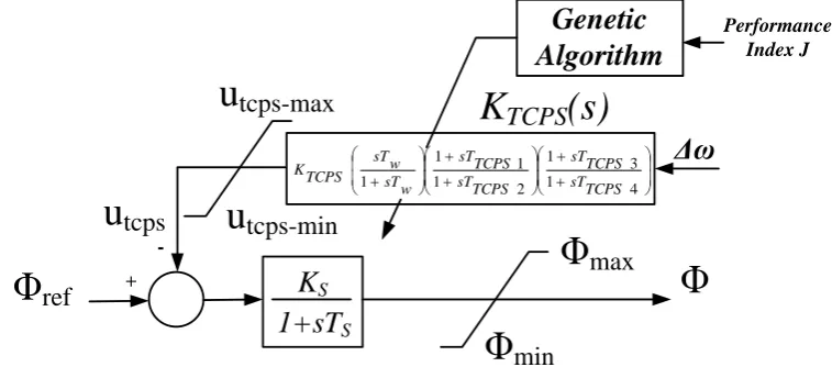
As the last stage for the TCPS controller design based on QFT, the loop shaping must be accomplished until QFT bounds at all frequency are satisfied and the closed-loop nominal system is stable. However, the manual loop shaping procedure is very difficult and takes long time. Therefore, the loop shaping procedure will be replaced by GA. To do this, the structure of the controller KTCPS(s)has been specified as shown in Fig. 5.
1+sT
SK
S 1 4
3 1 2 1 1 1
1 sTTCPS
TCPS sT TCPS sT TCPS sT w sT w sT TCPS K
Φ
Φ
max
Φ
min
u
tcps-max
u
tcps-min
u
tcps
Φ
ref
+
-Δω
Genetic
Algorithm
Performance Index JK
TCPS
(s)
Fig. 5. A Block diagram for selecting the TCPS controller parameters using GA
The optimized parameters using GA areKTCPS,Tw,TTCPS1,TTCPS2,TTCPS3andTTCPS4as shown in Fig. 5. In order to optimize these 6 parameters using GA, the objective function has been chosen as follows.
h i i _ bound i damp J J OJ min 1 1 (16)
where, andi(i1,2,3,...,h)are the weighting values. Jdampis the damping ratio for the dominant oscillation
mode andJbound_iis defined as the bound index which checks QFT bound satisfaction at i. Assuming that the eigenvalue corresponding to the dominant oscillation mode for the closed loop system is j, the damping ratioJdamp is given by,
2 2 damp
J (17)
value, the system is unstable. Therefore the very large value is assigned to the performance index (18) by force. The fitness function for evaluating the each string in GA is the proposed performance indexJ.The performance index Jused to select parameters of TCPS controller using the GA is defined as
h
i
i bound i
damp J
J J Index e Performanc
1
_ 1
1
(18)
IV.
SIMULATION
RESULTS
To select the parameters of the TCPS controller based on QFT as shown in Fig. 5, the real variable GA using the tournament selection method, the arithmetic crossover and the uniform mutation are used. The genetic algorithm optimization toolbox (GAOT) [21] has been used to optimize the parameters of the TCPS controller. The population size of the GA is 200 and the generation number is 200. The parameters of the designed TCPS controller based on QFT using GA are KTCPS= 36.6552,Tw = 99.7840,TTCPS1= 132.9217,TTCPS2= 71.3789,
3
TCPS
T = 34.4548 andTTCPS4= 19.9338.
Fig. 6 shows the loop shaping result using GA for the nominal open loop transfer function
) ( ) ( ) ( 0
0 s G sK s
L TCPS according toi. It is confirmed that the nominal open loop transfer function Lo(s) satisfied all QFT bounds at all selected frequency as shown in Fig. 4.
Fig. 6.QFT bounds and loop shaping result using GA
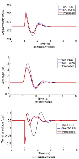
To verify the robust performance of the designed TCPS controller based on QFT using GA, the nonlinear simulations in time domain have been performed under the 3operating conditions of the power system. The proposed TCPS controller have been compared to those of the conventional simulated annealing based PSS (SA-PSS)[8] and the simulated annealing based TCPS (SA-TCPS) [8].The normal load condition is Pe1(p.u.) and Qe0.015(p.u.), the leading PF load condition is Pe0.7(p.u.) and Qe0.2(p.u.), and the heavy load
condition is Pe1.1[p.u.] and Qe0.4[p.u.]. The simulation constraints are ≤10, upss≤0.2(p.u.) and Efd
Table 1. Power system parameters
Generator parameters M=9.26, D=0, Tdo'=7.76, xd=0.973, xd'=0.19, xq=0.55
Exciter parameters KA=50, TA=0.05
Line parameters R=-0.034, X=0.997, G=0.249, B=0.262
TCPS parameters KS=1, TS=0.05
Initial conditions Pe0=1.0, Qe0=0.015, Vt0=1.05
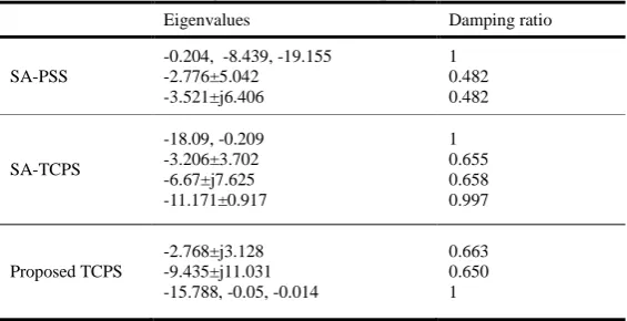
4.1 Normal load condition
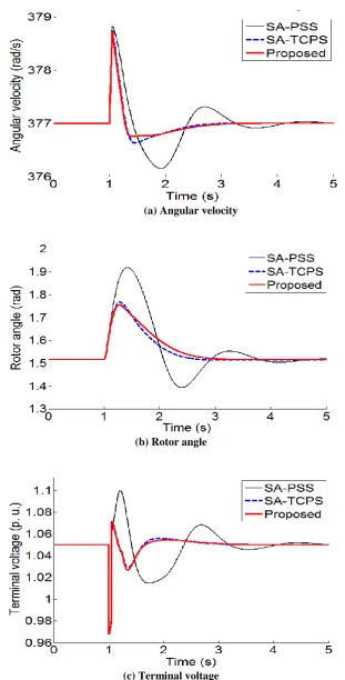
Table 2 shows the eigenvalues and damping ratio of closed loop with the conventional PSS, SA-TCPS and proposed SA-TCPS respectively. The damping ratio with the proposed SA-TCPS controller is improved in comparison with the conventional SA-PSS controller and the SA-TCPS controller. Fig. 7 shows the simulation results for angular velocity, rotor angle and terminal voltage with the SA-PSS, SA-TCPS and proposed TCPS under normal load in case that a 3-phase short circuit occurs near the infinite bus at 1.0s and is cleared at 1.1s without the power system configuration change. The first swing of angular velocity and rotor angle using the proposed TCPS controller is smaller than that using the conventional SA-PSS and SA-TCPS. The voltage profile is greatly improved with the SA-TCPS and proposed TCPS.
4.2Leading PF load condition
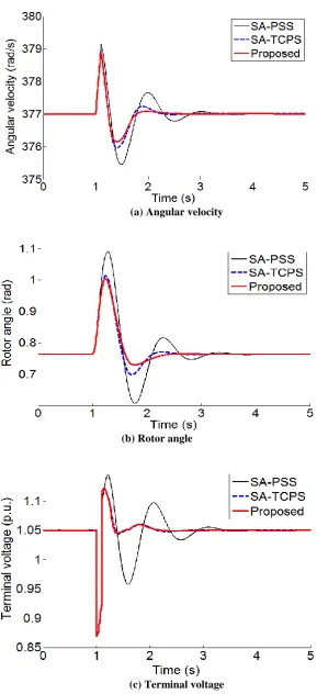
Fig. 8 shows the simulation results for angular velocity, rotor angle and terminal voltage with the SA-PSS, SA-TCPS and proposed TCPS under leading PF load in case that a 3-phase short circuit occurs near the infinite bus at 1.0s and is cleared at 1.1s without the power system configuration change. The first swing of angular velocity and rotor angle using the proposed TCPS controller is smaller than that using the conventional SA-PSS and SA-TCPS.
4.3 Heavy load condition
Fig. 9 shows the simulation results for angular velocity, rotor angle and terminal voltage with the SA-PSS, SA-TCPS and proposed TCPS under heavy load in case that a 3-phase short circuit occurs near the infinite bus at 1.0s and is cleared at 1.05s without the power system configuration change. The first swing of angular velocity and rotor angle using the proposed TCPS controller is smaller than that using the conventional SA-PSS and SA-TCPS.
Table 2. Eigenvalues and damping ratio
Eigenvalues Damping ratio
SA-PSS
-0.204, -8.439, -19.155 -2.776±5.042 -3.521±j6.406
1 0.482 0.482
SA-TCPS
-18.09, -0.209 -3.206±3.702 -6.67±j7.625 -11.171±0.917
1 0.655 0.658 0.997
Proposed TCPS
-2.768±j3.128 -9.435±j11.031 -15.788, -0.05, -0.014
(a) Angular velocity
(b) Rotor angle
(c) Terminal voltage
(a) Angular velocity
(b) Rotor angle
(c) Terminal voltage
(a) Angular velocity
(b) Rotor angle
(c) Terminal voltage
V.
C
ONCLUSIONIn this paper, the TCPS controller based on QFT using GA has been designed to enhance the power system stability. The QFT bounds and the damping ratio as the objective function of GA to select parameters of the TCPS controller has been used to design the robust controller. The robust performance of the proposed TCPS controller has been compared to those of the conventional SA-PSS and SA-TCPS. The main results in this paper are as follows.
① It is possible to automatically design the TCPS controller using the GA without a trial and error in loop shaping procedure.
② The simulation results show that the proposed TCPS controller endows better dynamic characteristics compared to that of conventional PSS.
③ The proposed TCPS controller can more significantly improve the voltage profile comparing with the conventional PSS.
REFERENCES
[1] F. P. Demello and C. Concordia, Concept of synchronous machine stability as affected by excitation control, IEEE Trans. on PAS, 88(4), 1969, 316-329.
[2] P. Kundur, D.C. Lee and H. M. Zein El-Din, Power system stabilizers for thermal unit: Analytical techniques and on-site validation, IEEE Trans on PAS, 100(1), 1981, 81-95.
[3] Yao-nan Yu, Electric power system dynamics, (ACADEMIC PRESS, 1983).
[4] M. R. Khaldi, A. K. Sarkar, K. Y. Lee and Y. M. Park, The modal performance measure for parameter optimization of power system stabilizers, IEEE Trans. on EC 8(4), 1993, 660-666.
[5] A. T. Al-Awami, Y. L. Abdel-Magid and M. A. Abido, A particle-swarm-based approach of power system stability enhancement with unified power flow controller, Electrical Power and Energy Systems, 29, 2007, 251-259.
[6] M. A. Abido, Pole placement technique for PSS and TCSC-based stabilizer design using simulated annealing, Electrical Power and Energy System, 22, 2000, 543-554.
[7] A.E. Hammad, Analysis of power system stability enhancement by static var compensators, IEEE Trans. on Power System, 1(4), 1986, 222-227.
[8] M. A. Abido, Simulated annealing based approach to PSS and FACTS based stabilizer tuning, Electrical Power and Energy Systems 22, 2000, 247–258.
[9] H. F. Wang, Damping function of unified power flow controller, IEE Proc.-Gener. Transm. Distrib., 146(1),1999, 81-87.
[10] H. F. Wang and F. Li F, Multivariable sampled regulators for the co-ordinated control of STATCOM AC and DC voltage, IEE Proc.-Gener. Transm. Disturb., 147(2), 2000, 93-98.
[11] Y. L. Tan and Y. Wang, Nonlinear excitation and phase shifter controller for transient stability enhancement of power systems using adaptive control law, Electrical Power and Energy Systems, 18(6), 1996, 397-403.
[12] H. F. Wang, F. J. Swift and M. Li, Analysis of thyristor-controlled phase shifter applied in damping power system oscillations, Electrical Power and Energy System, 19(1), 1997, 1-9.
[13] Y. L. Tan and Y. Wang, Design of series and shunt FACTS controller using adaptive nonlinear coordinated design technique, IEEE Trans. On Power Systems, 12(3), 1997, 1374-1379.
[14] G. El-Saady, A variable structure static phase shifting transformer for power system stabilization, Electric Power Systems Research, 50, 1999, 71-78.
[15] M. A. Abido, Thyristor controlled phase shifter based stabilizer design using simulated annealing algorithm, IEEE Power Tech ’99 Conference, Budapest, Hungary, 1999.
[16] A. A. Hashmani, Y. Wang and T. T. Lie, Enhancement of power system transient stability using nonlinear coordinated excitation and TCPS controller, Electrical Power and Energy Systems, 24, 2002, 201-214.
[17] M. A. Abido, Y. L. Abdel-Magid, Analysis of power system stability enhancement via excitation and facts-based stabilizers, Electric Power Components and Systems, 32, 2004, 75-91.
[18] R. J Abraham, D. Das and A. Patra, Effect of TCPS on oscillation in tie-power and area frequencies in an interconnected hydrothermal power system, IET Gener. Transm. Distrib. 1(4), 2007, 632-739.
[19] I. M. Horowitz, Survey of quantitative feedback theory (QFT), Int. J. Cont. 53(2), 1991,255-291.
[20] J. M. Rodrigues, Y. Chait Y and C. V. Hollot, An efficient algorithm for computing QFT bounds, Trans. of the ASME, 119, 1997, 548-552.