ISSN (e): 2250-3021, ISSN (p): 2278-8719
Vol. 09, Issue 8, August. 2019, ||Series -I || PP 53-62
Broad Band Microstrip Patch Antenna
Amit Das
1, Ashish Dubey
21,
Department of electronics& Communication,
2.
ShriRam College of Engineering & Management, Gwalior- 476444, India Received 12 August 2019; Accepted 26 August 2019
Abstract: Microstrip Patch Antenna (MPA) is generally used in modern communication devices, and a large part of day-to-day communication is done through it. Study of the literature of past few year shows that, the progressing work on MPA is focused on designing compact sized broadband microstrip antenna. But inherently MPA have narrow bandwidth, so to enhance bandwidth various techniques are used. This review paper describes some commonly engaged techniques to fabricate MPA with broader-bandwidth since last few decades. One of the advantages of microstrip patches over conventional antennas is their small size. However, there are many present day applications where even these small radiators are too large. A microstrip antenna incorporated with a single shorting pin is found to provide reduction in overall area with respect to a conventional patch. The compact circular polarized patch antennas can be achieved by slot loading on patch. In this paper the review on various techniques of compactness by Conductive bias, planar meta-material unit cell and slot loading on microstrip antenna are presented which are reported in literature.
Keywords:Compact patch, Pin loading, S-shaped impedance matching network with planar meta-material unit cell, Conductive .
I. INTRODUCTION
A Microstrip Antenna in its simplest form consists of a radiating patch on one side of dielectric substrate and ground plane on other side. Microstrip Patch Antennas are popular for their well-known attractive feature, such as a low profile, light weight, and compatibility with Monolithic Microwave Integrated Circuits (MMICs). Modern Communication System, Such as those for satellite links (GPS, Vehicular, etc.), as well as emerging applications, such as Wireless Local Networks (WLAN), offers antennas with compactness and low-cost, thus rendering planar technology useful, and sometimes unavoidable. Conventional microstrip patch antennas has some drawbacks of low efficiency, narrow bandwidth (3-6)% [1,2]of the central frequency, its bandwidth is limited to a few percentage which is not enough for most of the wireless communication system[3]. There are several designs have been investigated and reported to decrease the size of antenna [4] and to improve the bandwidth of antenna [5,6].
It has many applications in military, radar systems, mobile communications, global positioning system (GPS), remote sensing etc. In this review paper discuss on various techniques of compactness by pin and slot loading on microstrip antenna. A microstrip antenna incorporated with a single shorting post at proper position and size is found to provide reduction in overall area with respect to a conventional patch antenna. Also, the compact Circular polarized patch antennas can be achieved by slot loading on patch. The load of the slots or slits in the radiating patch can cause meandering of the excited patch surface current paths and result in lowering of the resonant frequency of the antenna, which corresponds to a reduced antenna size and compared to a conventional circularly polarized microstrip antenna at the same operating frequency. The size of the microstrip patch antenna is inversely proportional to the operating frequency of the antenna and the Bandwidth of the microstip patch antenna is directly proportional to the substrate thickness and inversely proportional to the square root of the dielectric constant of the substrate. Mostly low dielectric constant is used because it has a very high water absorption capability. Higher dielectric constants are used in microwave circuits because they require tightly bounds fields to minimize radiation and coupling and lead to smaller element sizes.
Broad Band Microstrip Patch Antenna
II. BANDWIDTH ENHANCEMENT OF DUAL ANTENNA DESIGN
Microstrip patch with DGS to increase its parameters and mostly bandwidth of the radiator is proposed. To attain an imperative bandwidth development, it has been suggested a rectangular formed symmetrical DGS in the surface plane. This DGS on the ground plane increases the fringing field which reluctantly increased the parasitic capacitance. This enhances the pairing between patch and surface which prepared the bandwidth to amplify from the crucial patch radiator. Size and shape of the DGS and site of the same plays a key role in the progress of the parameters or the bandwidth itself. Computer Simulation Software was utilized for simulation purpose.
Fig. 1 Rectangular compact segment radiator at 1.65GHz.
To intend the radiator first step is to calculate the required parameters which are involved in designing. After getting these required values, the simulated outcomes are obtained by using CST microwave studio (CST-MWS) simulation software. The Figure 1 shown above represents the structure of rectangular compact segment radiator at 1.65 GHz whose specifications for designing are mentioned below.
Fig 2 Simulated Result of RMPR illustrating return loss of -13.1dB at 1.65GHz.
Fig. 3 Radiation pattern at 1.65GHz.
The smith chart of the designed patch is shown in figure 4 below. This smith chart shows the perfect impedance matching which is 31.5 Ohm as compared to 50 Ohm, it has to be improved up to 50 Ohm.
Fig. 4 Smith chart of the proposed RMPR prior DGS introduction at 1.65GHz.
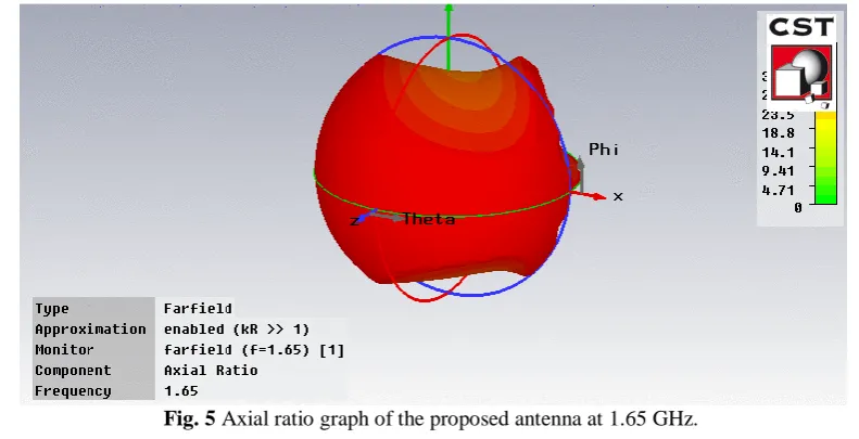
The axial ratio is defined as the ratio between the minor and major axis of the polarization ellipse. Recall that if the ellipse has an equal minor and major axis it transforms into a circle, and we say that the antenna is circularly polarized. In that case the axial ratio is unity.
Broad Band Microstrip Patch Antenna
The axial ratio is defined as the ratio between the minor and major axis of the polarization ellipse. Recall that if the ellipse has an equal minor and major axis it transforms into a circle, and we say that the antenna is circularly polarized. In that case the axial ratio is unity
Fig. 6 Theta pattern at 1.65GHz of the proposed antenna.
Theta waves generate the theta rhythm a neural oscillatory pattern in electroencephalography (EEG) signals, recorded either from inside the brain or from electrodes glued to the scalp.
Fig. 7 Phi pattern at 1. 65GHz of the proposed antenna.
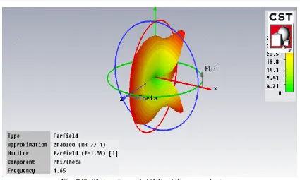
Fig 8 Phi/Theta pattern at 1. 65GHz of the proposed antenna.
Results of the simulated patch is not up to the mark and not fulfilling the requirement, so some amendments wants to be required, for that purpose DGS is introduced in the surface of patch radiator. This introduction of defect in ground plane modifies MPR characteristics to a large level e. g. return loss [34] and bandwidth after introduction of defected structure.
Fig. 9 Proposed DGS in the surface plane of MPR at 1.65GHz.
Broad Band Microstrip Patch Antenna
Fig.10 This is the simulated output of design proposed on surface plane in figure 10, dip at 1.65 GHz. Fig.10 Shows the return loss and bandwidth of proposed design at 1.65 GHz.
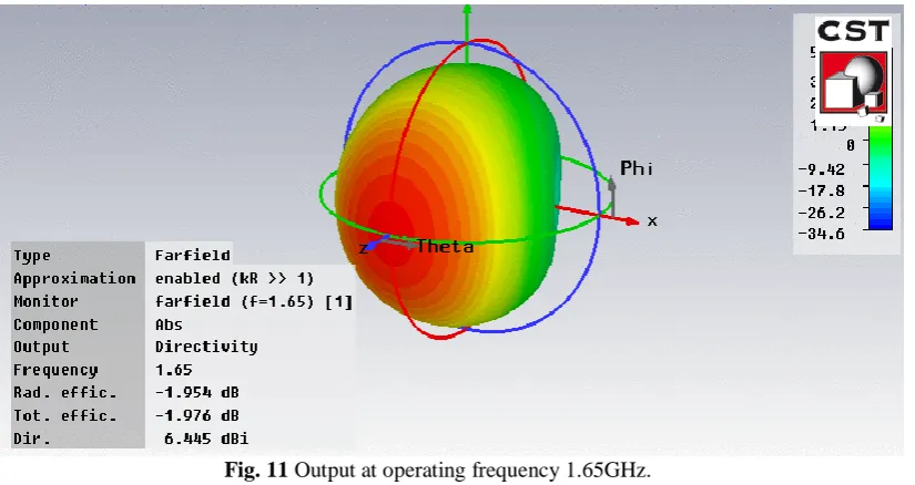
Fig. 11 Output at operating frequency 1.65GHz.
The Directivity plot (figure 12) represents amount of radiation intensity i.e is equal to 6.44 dBi. The simulated antenna radiates more in a particular direction as compared to the isotropic antenna which radiates equally in all directions, by an amount of 6.44 dBi from polar plot view of the directivity, it can be seen that at a frequency of 1.65GHz, directivity is 6.44dBi.
The above fig 12 shows the smith chart of the proposed design at 1.65 GHz. Smith chart is important chart for impedance matching and finding reflection efficient. This chart helps in finding reflection co-efficient and return loss of the proposed radiator.
Fig 13 Axial ratio graph of the proposed antenna at 1.65 GHz.
The axial ratio is defined as the ratio between the minor and major axis of the polarization ellips. Recall that if the ellipse has an equal minor and major axis it transforms into a circle, and we say that the antenna is circularly polarized. In that case the axial ratio is unity.
Fig 14 Theta pattern at 1. 65GHz of the proposed antenna.
Broad Band Microstrip Patch Antenna
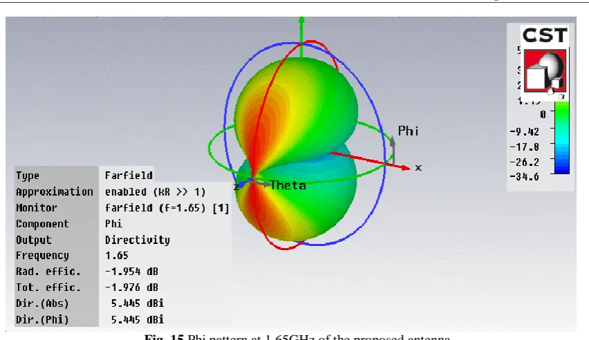
Fig. 15 Phi pattern at 1.65GHz of the proposed antenna.
Antennas typically have a single peak direction in the radiation pattern; this is the direction where the bulk of the radiated power travels. The radiation pattern is a plot which allows us to visualize where the antenna transmits or receive power.
Fig 16 Phi/Theta pattern at 1. 65GHz of the proposed antenna.
The comparison chart will be presented in below, the comparison of MPR after and before the introduction of defect in the ground plane will be presented, initially the designed patch at 1.65GHz showing radiation at 1.65GHz was not having the suitable parameters so to fulfill the need of current demand some amendments were made and after introducing the defected structure in ground plane a significant improvement is shown and comparison of the same is shown in Table 1
S. no. Parameters MPR at 1.65 GHz Post DGS implementation at 1.65 GHz
1 Return loss -13.1 dB -30 dB
2 Bandwidth 13.9 MHz 36.6 MHz
3 Directivity 5.783 dB 6.445 Db
4 Efficiency 66.23% 68.77%
After the comparison, it has been viewed that the projected DGS ameliorate the parameters up to a huge level, the proposed DGS method improves the return loss and increased the bandwidth above 100%.
III. CONCLUSION
Communication plays a very important role in today’s world as the switching of communication systems from “wired to wireless” has been very rapid. Antenna is one of the most important elements of wireless communication systems allowing the tranmission and reception of electromagnetic waves in free space. The design of an efficient, small size antenna providing large operating bandwidth for recent wireless applications is a major challenge. Thus, antenna design has become one of the most important and demanding aspect in the field of wireless communication. One of the most popular and frequently used in modern world antenna in this field is microstrip patch antennas. Microstrip antennas are widely used for its low profile, easy manufacturability, simple structure, low cost and omni directional radiation patterns[1].These features have much more advantage over the traditional ones. But the drawback of this kind of antenna also sometimes confine their applications, especially the narrow bandwidh. So, new technologies is invented to overcome these shortcomings. One such technique that can be used to overcome these limitations is Defected Ground Structure (DGS). Recently there has been an increasing in the use of DGSs for performance enhancement of microstrip antennas. These structures are realized by etching off a simple shape defect from the ground plane of microstrip patch antenna [2]
IV. SUMMARY OF THE CHAPTER
The designed antenna is designed to use in L band. Antenna will be able to work in the L band by applying a resonant frequency of 1.85 GHz. Return losses of the propagating frequencies increased from -10.1 dB to -35 dB as well as Bandwidth of the antenna increased up to 100 % after introduction of DGS.
REFERENCES
[1]. Nasser Ojaroudi*, Mohammad Ojaroudi, and Yaser Ebazadeh “UWB/Omni-Directional Microstrip Monopole Antenna for Microwave Imaging Applications “.Progress In Electromagnetics Research C, Vol. 47, 139- 146, 2014.
[2]. A.Kasinathan, Dr.V.Jayaraj,M.Pachiyaannan,” E-Shape Microstrip Patch Antenna Design for Wireless Applications” IJISET - International Journal of Innovative Science, Engineering & Technology, Vol. 1 Issue 3, May 2014.
[3]. T.Suganthi1, Dr.S.Robinson2, G.Kanimolhi3, T.Nagamoorthy4” Design and Analysis of Rectangular Microstrip Patch Antenna for GSM Application” IJISET - International Journal of Innovative Science, Engineering & Technology, Vol. 1 Issue 2, April 2014.
[4]. Darshana R. Suryawanshi, Prof. Bharati A. Singh,A Compact Rectangular Monopole Antenna with Enhanced Bandwidth, IOSR Journal of Electronics and Communication Engineering (IOSR-JECE), Volume 9, Issue 2, Ver. VII (Mar - Apr. 2014), PP 54-57.
[5]. Reza Jafarlou, Changiz Ghobadi, Javad Nourinia “Design, Simulation, and Fabrication of an Ultra-Wideband Monopole Antenna for Use in Circular Cylindrical Microwave Imaging Systems “Australian Journal of Basic and Applied Sciences, 7(2): 674-680, 2013 ISSN 19918178.
[6]. Ramna1,Amandeep Singh Sappal,” Design Of Rectangular Microstrip Patch Antenna Using Particle Swarm Optimization” International Journal of Advanced Research in Computer and Communication Engineerin Vol. 2, Issue 7, July 2013.
[7]. W. Mazhar, M. A. Tarar, F. A. Tahir, Shan Ullah, and F. A. Bhatti “Compact Microstrip Patch Antenna for Ultra-wideband Applications” PIERS Proceedings, Stockholm, Sweden, Aug. 12{15, 2013.
[8]. N. Ojaroudi, M. Ojaroudi, F. Geran, and Sh. Amiri “Omni-Directional/Multi-Resonance Monopole Antenna for Microwave Imaging Systems”. 20th Telecommunications forum TELFOR 978-1-4673-2984- 2012 IEEE.
[9]. Jawad K. Ali, Mahmood T. Yassen, Mohammed R. Hussan, and Mohammed F. Hasan” A New Compact Ultra Wideband Printed Monopole Antenna with Reduced Ground Plane and Band Notch Characterization” Progress In Electromagnetics Research Symposium Proceedings, KL, MALAYSIA, March 27–30, 2012 1531.
[10]. S. M. Naveen, R. M. Vani, P. V. Hunagund,“Compact Wideband Rectangular Monopole Antenna for Wireless Applications1” Wireless Engineering and Technology, 2012, 3, 240-243.
Broad Band Microstrip Patch Antenna
International organization of Scientific Research 62 | Page [12]. Mohammad Ojaroudi, Changiz Ghobadi, and Javad Nourinia “Small Square Monopole Antenna With Inverted T-Shaped Notch in the Ground Plane for UWB Application” IEEE ANTENNAS AND WIRELESS PROPAGATION LETTERS, VOL. 8, 2009.
[13]. Y. Chen, S. Yang, S. He, and Z. Nie, Design And Analysis Of Wideband Planar Monopole Antennas Using The Multilevel Fast Multipole Algorithm, Progress In Electromagnetics Research B, Vol. 15, 95-112, 2009.
[14]. Nakchung Choi, Changwon Jung, Joonho Byun, Frances J. Harackiewicz, Senior Member, IEEE,
Myun-Joo Park,Yong-Seek Chung, Taekyun Kim, and Byungje Lee.