Static Analysis of Crane Hook with I- Section and T- Section
using Ansys
,M.Amareswari Reddy1 ,M.N.V Krishnaveni2,B.Nagaraju3 , M RajaRoy4
1,2,3,4ANITS College of Engineering, Department of Mechanical Engineering, Visakhapatnam-531162
Abstract—Crane hooks are highly liable components that are typically used for industrial purposes. Failure of a crane hook mainly depends on three major factors i.e. dimension, material. In this paper load carrying capacity is studied by varying the cross sections. The selected sections are I-section and T-section. The area remains constant while changing the dimensions for the two different sections. The crane hook is modelled using SOLIDWORKS software. The stress analysis is done using ANSYS 14.0 workbench Educational version. It is found that T cross section yields minimum stresses at the given load of 6 ton for constant cross section area among two cross sections. The stress distribution pattern is verified for its correctness on model of crane hook using Winkler-Bach theory for curved beams.
Keywords— Crane hook, Static analysis,
Winkler-Bach theory, ANSYS 14.0.
I. INTRODUCTION
Crane Hooks are highly responsible components that are typically used for handling material in industries. It is basically a hoisting fixture designed to engage a ring or link of a lifting chain or the pin of a shackle or cable socket and must follow the health and safety guidelines. Thus, the aim of the work is to study the stress distribution pattern of a crane hook using finite element method and to verify the results using scathing method.
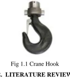
The lifting of material generally occurs on construction sites, in factories and other industrial situations. Correct lifting can move large objects efficiently and reduce manual handling operations. Improper design of crane hooks lead to disastrous accidents. Every year, incorrect lifting procedures cause injuries, loss of work time and property. People, machinery, loads, methods and the work environment, are all important factors for correct lifting. Provided that enough safety measures are fully implemented, lifting accidents can be reduced. The Fig 1.1 as shows the general diagrams of crane hook.
Fig 1.1 Crane Hook
2. LITERATURE REVIEW
Crane hooks are the components which are generally used to elevate the heavy load in industries and constructional sites. Recently, excavators having a crane-hook are widely used in construction works site. One reason is that such an excavator is convenient since they can perform the conventional digging tasks as well as the suspension works. Another reason is that there are work sites where the crane trucks for suspension work are not available because of the narrowness of the site. In general an excavator has superior manoeuvrability than a crane truck. However, there are cases that the crane hooks are damaged during some kind of suspension works. From the view point of safety, such damage must be prevented. Identification of the reason of the damage is one of the key points toward the safety improvement. If a crack is developed in the crane hook, mainly at stress concentration areas, it can cause fracture of the hook and lead to serious accidents. In ductile fracture, the crack propagates continuously and is more easily detectable and hence preferred over brittle fracture. In brittle fracture, there is sudden propagation of the crack and the hook fails suddenly. This type of fracture is very dangerous as it is difficult to detect.
Ajeet Bergaley and Anshuman Purohit [1] described their work on structural Analysis of Crane Hook Using Finite Element. Crane hook are highly significant component used for lifting the load with the help of chain or links. Crane hook is purchased from the local market for finite element analysis. The hook was tested on the UTM machine in tension to locate the area having maximum stress and to locate the yield point. The model of hook is prepared in CAE software having dimension and material similar to the crane hook which was purchased from the market. The results obtained were compared with theoretical analysis. Then cross section in which minimum stress induced for given load was modified through FEM.
method. Crane hooks are one of the important components which are used to transfer materials having heavy loads, mainly in industries. Crane hooks are liable components subjected to failure due to stress in accumulation of heavy loads. The design parameters for crane hook are area of cross section, material and radius of crane hook. In the present work optimization of design parameters is carried out using Taguchi method, total three parameters are considered with mixed levels and L16 orthogonal array is generated .The optimum combination of input parameters for minimum Von-misses stresses are determined.
Rashmi Uddan wadikerin [3] discussed on stress analysis of crane hook and validation by photo-elasticity. Crane hooks are highly liable components and are always subjected to failure due to accumulation of large amount of stresses which can eventually lead to its failure. To study the stress pattern of crane hook in its loaded condition, a solid model of crane hook is prepared with the help of CMM and CAD software. Real time pattern of stress concentration in 3D model of crane hook is obtained. The stress distribution pattern is verified for its correctness on an acrylic model of crane hook using Diffused light Polari scope set up. By predicting the stress concentration area, the shape of the crane is modified to increase its working life and reduce the failure rates.
III DESIGN OF CRANE HOOK
Machine frames having curved portions are frequently subjected to bending or axial loads or to a combination of bending and axial loads. With the reduction in the radius of curved portion, the stress due to curvature become greater and the results of the equations of straight beams when used becomes less satisfactory. For relatively small radii of curvature, the actual stresses may be several times greater than the value obtained for straight beams. It has been found from the results of Photo elastic experiments that in case of curved beams, the neutral surface does not coincide with centroidal axis but instead shifted towards the Centre of curvature. It has also been found that the stresses in the fibers of a curved beam are not proportional to the distances of the fibers from the neutral surfaces, as is assumed for a straight beam.The design of crane hook was done by taking the data pertaining to load(w), C.S.A and curvatures which are used in industrial applications of crane hook
3.1 Theoretical Design of Crane Hook with I C.S.A Considering the dimensions of the JCB’s crane hook at Kommadi, Visakhapatnam. P =6 Ton=58860 N ;R1= 60.625 mm; R4= 139.375 mm; H = 80 mm ; b1=72 mm; b2=32 mm b3=72 mm t1=20 mm t2=44 mm t3=16 mm with these values we done a modelling in SOLIDWORKS with I cross section as shown in Fig 3.1.
Total equivalent stress,
Direct stress due to load,
Bending stress due to load,
P=6 Ton= 58860 N
R1 = 60.625 mm ,R2= 80 mm,R3 = 124 mm,R4 = 139.375 mm
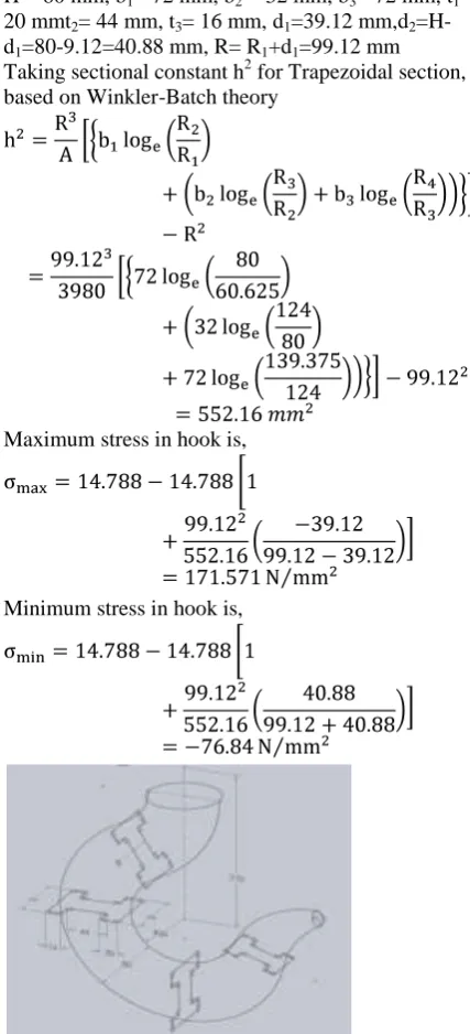
H = 80 mm, b1= 72 mm, b2 = 32 mm, b3= 72 mm, t1= 20 mmt2= 44 mm, t3= 16 mm, d1=39.12 mm,d2 =H-d1=80-9.12=40.88 mm, R= R1+d1=99.12 mm Taking sectional constant h2 for Trapezoidal section, based on Winkler-Batch theory
Maximum stress in hook is,
Minimum stress in hook is,
Fig 3.1 Design of Crane Hook with I C.S.A
T-section, based on Winkler- Batch theory
Total equivalent stress, Direct stress due to load,
Bending stress due to load,
Here the moment due to load is taken negative sign as the load straightening curvature of hook,
Total Stress at Inner layer of the hook is maximum, since both are of tensile in nature
Total Stress at Outer layer of the hook is minimum, since both are stresses are of opposite in nature
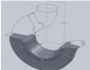
Fig 3.2 Design of Crane Hook with T C.S.A
IV MODELLING OF CRANE HOOK USING SOLIDWORK
Building a model in SOLIDWORKS usually starts with a 2D sketch (although 3D sketches are available for power users). The sketch consists of geometry such as points, lines, arcs, conics (except the hyperbola), and splines. Dimensions are added to the sketch to define the size and location of the geometry.
Relations are used to define attributes such as tangency, parallelism, perpendicularity, and concentricity. The parametric nature of SOLIDWORKS means that the dimensions and relations drive the geometry, not the other way around. The dimensions in the sketch can be controlled independently, or by relationships to other parameters inside or outside of the sketch.
In an assembly the relations are mates. Just as sketch relations define conditions such as tangency, parallelism, and concentricity with respect to sketch geometry, assembly mates define equivalent relations with respect to the individual parts or components, allowing the easy construction of assemblies. SOLIDWORKS also includes additional advanced mating features such as gear and cam follower mates, which allow modelled gear assemblies to accurately reproduce the rotational movement of an actual gear train.
Finally, drawings can be created either from parts or assemblies. Views are automatically generated from the solid model, and notes, dimensions and tolerances can then be easily added to the drawing as needed. The drawing module includes most paper sizes and standards (ANSI, ISO, DIN, GOST, JIS, BSI and SAC).
Fig 4.1SolidworksModel of Crane Hook with I-section
Fig 4.2Solidworks Model of Crane Hook with
V FINITE ELEMENT ANALYSIS OF CRANE HOOK USING ANSYS WORKBENCH
The finite element method has become a dominant tool for the numerical solution of wide range of engineering problems. Applications range from deformation and stress analysis of automotive aircraft, building, and bridge structures with advances in computer technology and CAD systems, complex problems can be modelled with relative alleviate.
In this method of analysis, a complex region defining a continuum is discretize into simple geometric shapes called finite elements. The material properties and the governing relationships are considered over these elements and considering the loading and constraints, results in a set of equations. Solution of these equations gives us the approximate behaviour of the continuum.
VI RESULTS AND DISCUSSION
In this paper the two sections of crane hooks of four different materials are designed according to curved beam concept. Stresses are found for 6 Ton load using curved beam concept.
Total model is modelled in SOLIDWORKS and IGES model is imported in to ANSYS, here top side of hook is fixed and at the inner curvature of hook 58860 N (6 Ton) load is applied on nodes and stresses and deformation are plotted.
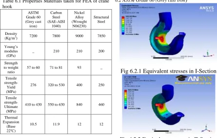
Table 6.1 Properties Materials taken for FEA of crane hook
ASTM Grade 60 (Grey cast
iron)
Carbon Steel (SAE-AISI
1040)
Nickel Alloy (Wrought
N06230)
Structural Steel
Density
(Kg/m3) 7200 7800 9000 7850
Young’s modulus (GPa)
_ 210 210 200
Strength to weight ratio
57 to 60 71 to 81 93 _
Tensile strength-Yield (MPa)
276 320 to 530 400 250
Tensile strength-Ultimate (MPa)
410 to 430 550 to 630 840 460
Thermal Expansion
(Base 22oC)
10.5 11.9 12 12
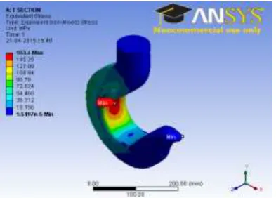
6.1 Structural Steel
Fig 6.1.1 Equivalent stresses in T-Section
Fig 6.1.2 Equivalent stresses in I-Section
6.2 ASTM Grade 60 (Grey cast iron)
Fig 6.2.1 Equivalent stresses in I-Section
Fig 6.2.2 Equivalent stresses in T-Section
Fig 6.3.1 Equivalent stresses in T-Section
Fig 6.3.2 Equivalent stresses in I-Section
6.4 Carbon Steel
Fig 6.4.1 Equivalent stresses in T-Section
Fig 6.4.2 Equivalent stresses in I-Section
6.5 Values of Maximum Stresses in Different Cross Sections
Table 6.2 Comparison of Stresses in Different Cross
Sections SECTI ON NAME ARE A OF CR OSS SEC TIO N (mm 2) INN ER RAD IUS OF CUR VAT URE (mm) LO AD (To n) THE ROT ICA L STR ESS (N/m
m2) ANS
YS
STR
ESS
(N/m
m2)
Nick el Allo y ANS YS STR ESS (N/m
m2)
Struc tural Steel ANS YS STR ESS (N/m
m2)
AST M Grad e 60 (Gre y cast iron) ANS YS STR ESS (N/m
m2)
Carb on Steel (SA E-AISI 1040 ) I- SECTI ON
3980 60 6 171.
571 165. 58 166. 72 167. 22 166. 72 T - SECTI ON
3980 60 6 174.
07 163. 4 163. 53 163. 73 163. 53
Theoretical stresses calculated based on Winkler-Batch theory and the corresponding crane hook model stresses determined by using ANSYS were tabulated as shown above and found that the deviations are at minimum of 5%. The factor of safety for crane hook under static analysis is 2 based on yield stress value.
VII CONCLUSION
VIIIREFERENCES
[1] AjeetBergaley and AnshumanPurohitdescribed their work on “Structural Analysis of Crane Hook Using Finite Element” International Journal of Science and Modern Engineering (IJISME) ISSN: 2319-6386, Volume-1, Issue-10, September 2013
[2] A.Gopichand carried an optimization of design parameters for “Crane Hook Using Taguchi Method” International Journal of Science and Modern Engineering (IJISME) ISSN: 2319-8753 An ISO 3297: 2007 Certified Organization Vol. 2, Issue 12, December 2013
[3] RashmiUddanwadikerin discussed on “Stress Analysis of Crane Hook and Validation by Photo-Elasticity” International Journal of Engineering Research & Technology ISSN: 2278-0181 Vol.3 - Issue 1 (January - 2014)
[4]Chetan N. Benkar explained the “Finite Element Stress Analysis of Crane Hook with Different Cross Sections” International Journal for Technological Research in Engineering ISSN (Online): 2347 – 4718 Volume 1, Issue 9, May-2014
[5] Ismail Gerdemeli, G. U. Rajurkar, Dr. D. V. Bhope, Prof. S. D. Khamankar explained the “Finite Element Analysis of the Tower Damage which Occurs Due to Heavy Loads” International Journal of Engineering Research & Technology ISSN: 2278-0181 Vol.2 - Issue 8 (August -2013)
[6] ShyamLal Sharma, Tasmeem Ahmad Khan, Md. Parvez and KamleshKumariexperimented on “Design of Hoisting Arrangement of E.O.T. Crane (2008) International Journal of Engineering & Robotics Research ISSN 2278 – 0149 Vol. 2, No. 3, July 2013
[7] Santosh Shaun, RiteshDewangan, ManasPatnaik and NarendraYadav describes the “Study of Crane Hook Having Trapezoidal Section by Finite Element Method & Design of Experiments” International Journal of Modern Engineering Research (IJMER)ISSN: 2249-6645 Vol.2, Issue.4, July-Aug 2012 PP-2779-2781
[8] Takuma Nishimura, Takao Muromakiet, Kazuyuki Hanahara, Yukio Tada, Shigeyuki Kuroda and Tadahisa Fukui “Damage Factor Estimation of Crane-Hook (A Database Approach with Image, Knowledge and Simulation)”, 4th International Workshop on Reliable Engineering Computing (REC 2010).