International Journal of Advanced Technology in Engineering and Science www.ijates.com
Volume No 03, Special Issue No. 01, March 2015 ISSN (online): 2348 – 7550
632 |
P a g e
THE STUDY OF DYNAMIC BEHAVIOUR OF
INTERLINKEDPOWER SYSTEM USING SIMULINK
,
Sumanta Kumar Nanda
2,
Sanjoy Mandal
31,2
M.Tech Student ,
3Associate Professor, Department of Electrical Engg.
ISM, Dhanbad, (India)
ABSTRACT
Practically all power system is interconnected in nature. In multi area interlinked power system the variation in load is a big obstacle .The basic intent of automatic load frequency control is to maintain total generation of system with total system requirement so that the frequency and the real power exchange with associated system are unaffected. Any dissembling between generated power and the consumed power results variation in system frequency scheduled frequency. The variation in frequency causes the system collapse, so in order to avoid such a problem we have to control the frequency variation in interlinked power system. This paper presents different Simulink results which shows the dynamic behavior of multi area interrelated power system with different conventional controller with 1% step load change, and it is found that these results are improved with the help of optimal control technique i.e. LQR method.
Keywords
:
Automatic generation control, tie line power, optimal controller, Area control error etc.
I INTRODUCTION
International Journal of Advanced Technology in Engineering and Science www.ijates.com
Volume No 03, Special Issue No. 01, March 2015 ISSN (online): 2348 – 7550
633 |
P a g e
II MODELLING OF POWER SYSTEM
2.1 An isolated power system with ALFC
Fig .1: Single area power system without controller
Where Δwis the change in frequency for a step change in load. Here the change in frequency is not zero, so to keep frequency at its schedule value,a PI controller will be use.
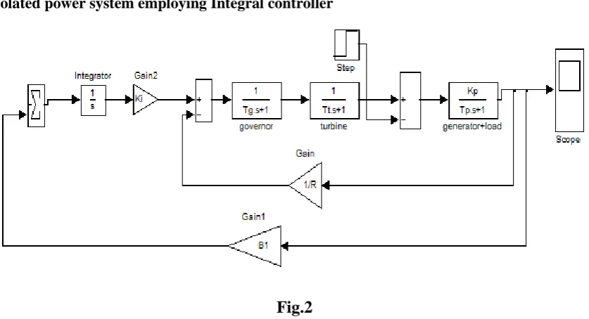
2.2 Isolated power system employing Integral controller
Fig.2
The automatic load frequency control loop (ALFC) is shown in fig.2.Here we use secondary loop which keeps thefrequency its nominal value. To maintain Δw=0 an integrator is used. Basically the integrator is used to measure the average error during a particularperiod of time and will remove the offset. The ability to retain its nominal value, this property of integrator is called rest action. As load on system changes continuously, so to maintain frequency at its nominal value the generation is adjusted automatically[16].
Δw
ΔPm
International Journal of Advanced Technology in Engineering and Science www.ijates.com
Volume No 03, Special Issue No. 01, March 2015 ISSN (online): 2348 – 7550
634 |
P a g e
2.3 Designing of two area interlinked power system using integral controller
Fig.3
The block diagram representation of two interlinked power system with non-reheat turbine shown in fig.3. The two area are interconnected with the help of tie line.Both the area are provided by integral controller. There are total nine blocks which represent whole two area interconnected power system. The state equation can be
formed easily with the help of transfer function of blocks. There are two controlling input named and [2]
[5] [9].
Equation of controlling input is written as For area 1
)………. (1)
For area 2
International Journal of Advanced Technology in Engineering and Science www.ijates.com
Volume No 03, Special Issue No. 01, March 2015 ISSN (online): 2348 – 7550
635 |
P a g e
2.4 Linearization of two area interconnected power system using state space analysis
Fig.4
The generalized state space representation of two interconnected power system shown in fig.4. d1 and d2 are the disturbances in area1 and area2 respectively.
The state equations can be written as For block 1
= Kp1 (
= - + ……….. (3)
For block 2
……….……… (4)
International Journal of Advanced Technology in Engineering and Science www.ijates.com
Volume No 03, Special Issue No. 01, March 2015 ISSN (online): 2348 – 7550
636 |
P a g e
……….. (5)For block 4
……… (6)
For block 5
……… (7)
For block 6
……… (8)
For block 7
……… (9)
For block 8
……….. (10)
For block 9
………. (11)
In general form these state equation can be written in single state equation
……… (12)
Where A is a matrix of order 9×9 called state matrix, B is a matrix of order 9×2 called control matrix and F is a matrix of order 9×2.
And the vector ‗x‘,‗d‘, ‗u‘ is written as
x= [ , u = , d=
2.5 Designing of optimal controller
The performance of system can be described in terms of cost which is to be minimized by LQR technique.
J = ……… (13)
Where ‗Q‘ is ‗state weight matrix‘ which is positive semi definite matrix. And ‗R‘ is control semi definite symmetric weight matrix. The value of Q and R chosen according to requirement of the system.
International Journal of Advanced Technology in Engineering and Science www.ijates.com
Volume No 03, Special Issue No. 01, March 2015 ISSN (online): 2348 – 7550
637 |
P a g e
Where feedback gain matrix ‗K‘ is obtained by the solution of Riccati equation, which is given as……… (14) ……….. (15)
The system with state feedback is given by
For the stability of system the eigenvalues of must have negative real part.
By MATLAB command
III SIMULATION RESULTS
The results of Simulink are shown with PI and PID controller and the disturbance is taken as 1% for the systems. Later these results are improved by advance optimal control system.
0 1 2 3 4 5 6 7 8 9 10
-0.08 -0.07 -0.06 -0.05 -0.04 -0.03 -0.02 -0.01 0
time(sec)
ch
an
ge
in
f
re
qu
en
cy
Frequency response of single area without controller
0 2 4 6 8 10 12 14 16 18 20
-0.07 -0.06 -0.05 -0.04 -0.03 -0.02 -0.01 0 0.01
time(sec)
c
h
a
n
g
e
i
n
f
re
q
u
e
n
c
y
Frequency response of single area using integral controller
Δw1
International Journal of Advanced Technology in Engineering and Science www.ijates.com
Volume No 03, Special Issue No. 01, March 2015 ISSN (online): 2348 – 7550
638 |
P a g e
0 2 4 6 8 10 12 14 16 18 20
-0.12 -0.1 -0.08 -0.06 -0.04 -0.02 0 time(sec) ch an ge in fr eq ue nc y
Frequency response of two area without controller
0 2 4 6 8 10 12 14 16 18 20
0 0.2 0.4 0.6 0.8 1 1.2 1.4 time(sec) MW
Power deviation of two area without controller
0 5 10 15 20 25 30
-0.07 -0.06 -0.05 -0.04 -0.03 -0.02 -0.01 0 0.01 time(sec) ch an ge in fr eq ue nc y
Frequency response of two interlinked power systemusing integral controller
0 5 10 15 20 25 30
-0.2 0 0.2 0.4 0.6 0.8 1 1.2 1.4 1.6 time(sec) MW
Power deviation response of two interlinked power system using integral controller
International Journal of Advanced Technology in Engineering and Science www.ijates.com
Volume No 03, Special Issue No. 01, March 2015 ISSN (online): 2348 – 7550
639 |
P a g e
0 5 10 15 20 25 30
-0.12 -0.1 -0.08 -0.06 -0.04 -0.02 0 0.02 0.04 0.06 time(sec) ch an ge in f re qu en cy
Frequency response of three interlinked power system using integral controller
0 5 10 15 20 25 30
-0.2 0 0.2 0.4 0.6 0.8 1 1.2 1.4 1.6 1.8 time(sec) MW
Power deviation of three interlinked power system using integral controller
0 2 4 6 8 10 12 14 16 18 20
-0.05 -0.04 -0.03 -0.02 -0.01 0 0.01 time(sec) ch an ge in fr eq ue nc y
Frequency response of twointerlinked power system using PID controller
0 2 4 6 8 10 12 14 16 18 20
0 0.2 0.4 0.6 0.8 1 1.2 1.4 time(sec) MW
Power deviation response of two interlinked power system using with PID controller
Δw1
Δw2
Δw3
Δw1
Δw2
ΔPm2
ΔPm1
ΔPm1
ΔPm2
ΔPm3
International Journal of Advanced Technology in Engineering and Science www.ijates.com
Volume No 03, Special Issue No. 01, March 2015 ISSN (online): 2348 – 7550
640 |
P a g e
0 2 4 6 8 10 12 14 16 18 20
-0.05 -0.04 -0.03 -0.02 -0.01 0 0.01 time(sec) ch an ge in f re qu en cy
Frequency response of three interlinked power system using with PID controller
0 2 4 6 8 10 12 14 16 18 20
-0.2 0 0.2 0.4 0.6 0.8 1 1.2 1.4 time(sec) MW
Power response of three interlinked power system using with PID controller
0 2 4 6 8 10 12 14 16 18 20
-0.01 -0.009 -0.008 -0.007 -0.006 -0.005 -0.004 -0.003 -0.002 -0.001 0 time(sec) ch an ge in fr eq ue nc y
Frequency response of single area using optimal controller
0 2 4 6 8 10 12 14 16 18 20
-0.06 -0.05 -0.04 -0.03 -0.02 -0.01 0 0.01 0.02 t(sec) f(h z)
with PID after block reducton with integral control
optimal full order controller
Comparative study of simulation result (for first area)
International Journal of Advanced Technology in Engineering and Science www.ijates.com
Volume No 03, Special Issue No. 01, March 2015 ISSN (online): 2348 – 7550
641 |
P a g e
0 2 4 6 8 10 12 14 16 18 20
-0.08 -0.07 -0.06 -0.05 -0.04 -0.03 -0.02 -0.01 0 0.01
time(sec)
c
h
a
n
g
e
i
n
f
re
q
u
e
n
c
y
Frequency response of two interlinked power system optimal controller (LQR technique)
IV CONCLUSIONS
In this paper the dynamic behavior of single area, two area and three area interlinked power system is examine with various controllers. It is found that PID controller gives better performance than PI controller. We have also tried to develop an optimal controller for two area interconnected power system. Finally it is concluded that LQR method gives more improved response in comparison to PI and PID controller.
Appendix:
System parameters – pu
pu pu pu
pu
pu pu pu
2*pi* pu
pu pu pu
Δw1
International Journal of Advanced Technology in Engineering and Science www.ijates.com
Volume No 03, Special Issue No. 01, March 2015 ISSN (online): 2348 – 7550
642 |
P a g e
puFor PID controller (3 area power system)
0.63 0.74 0.93
0.91 0.875 1.0
1.20 1.15 1.2
REFERENCES
Journal Papers
1. J. Nanda, M. Parida, and A. Kalam, "Automatic generation control of a multi-area power system with conventional integral controllers," presented at the Australian Univ. Power Engg. Conf., Melbourne, Australia, 2006.
2. A. Khodabakhshian and M. Edrisi, “A new robust PID load frequency controller”, Control Engg.
Pract., vol. 16, no. 9, pp. 1069–1080, 2008.
3. Ibraheem, P. Kumar and D.P. Kothari, “Recent philosophies of automatic generation control
strategies in power systems,” IEEE Trans. Power System 20 (1) (2005), pp. 346–357.
4. C. Concordia and L. K. Kirchmayer, “Tie-line power & frequency control of electric power system:
Part II,” AISE Trans, III-A, vol. 73, pp. 133-146, Apr. 1954.
5. Yao Zang, Tsinghua “Load Frequency Control of Multiple-Area Power Systems“University July, 2007
Master of Science in Electrical Engineering.
6. K. C. Divya, and P.S. Nagendra Rao, “A simulation model for AGC studies of hydro-hydro systems‘‘, Int. J. Electrical Power & Energy Systems, Vol. 27, Jun.- Jul. 2005, pp. 335-342.
7. K. P. Singh Parmar, S. Majhi, D. P. Kothari, “ Optimal Load Frequency Control of an Interconnected
Power System,’’ MIT International Journal of Electrical and Instrumentation Engineering, vol. 1, No. 1, pp 1-5, Jan 2011.
8. W.S. Levin, M Athans, ―On the determination of the optimal constant output feedback gains for linear Multivariable systems,” IEEE Trans. On Automatic control, Vol AC-15, no.1, 1970.
9. K.P. Singh Parmar, S. Majhi and D. P. Kothari, “Multi-Area Load Frequency Control in a Power
System Using Optimal Output Feedback Method”, IEEE Conf. proceedings, PEDES 2010 New Delhi, India.
10. Yogendra Arya, Narendra Kumar, S.K. Gupta, ―Load Frequency Control of a FourArea Power System
using Linear Quadratic Regulator”, IJES Vol.2 2012 PP.69-76.
International Journal of Advanced Technology in Engineering and Science www.ijates.com
Volume No 03, Special Issue No. 01, March 2015 ISSN (online): 2348 – 7550
643 |
P a g e
12. E. C. Tacker, T. W. Reddoch, O. T. Pan, and T. D. Linton, “Automatic generation Control ofelectric energy systems—A simulation study‖, IEEE Trans. Syst. Man Cybern., vol. SMC-3, no. 4, pp. 403–5, Jul. 1973.
13. O.I. Elgerd and C. Fosha,“Optimum megawatt frequency control of multi-area electric energy
systems”, IEEE Trans Power Appl Syst 89(4) (1970), pp. 556–563.
Books:
14. Hadi saadat, eds 1999. Power System Analysis, McGraw-Hill International edition, Singapore.
15. P. Kundur, Power System Stability & Control. Tata McGraw Hill, New Delhi, Fifth reprint 2008, pp. 581-626.