BENDING STRESS ANALYSIS OF SPUR GEAR BY USING
MODIFIED LEWIS FORMULA
1
Namrata S.Gadakh,
2Prof. R.S. Shelke
1
P.G. Scholar Mechanical SVIT Nashik Pune University
2
Assistant Professor (Mechanical Dept.) SVIT Nashik, MS (India)
ABSTRACT
Gears are one of the most important component in mechanical power transmission systems. The bending stress of the gear tooth is regarded as one of the key contributors for the failure of the gear in the gear set. Thus, analysis of stresses has become popular as an area of study on gears to minimize the chances of failures and also for the optimal design of gears. The analytical study is based on Modified Lewis formula. The project is basically concerned with ANALYSIS of SPUR gears which are actually used in all types of two wheelers. For doing analysis I taken the SPLENDOR of HERO HONDA company. I can determined stress in tooth of spur gear by using Modified Lewis equation.
Keyword: Bending stress, Spur gear, Modified Lewis theory
I. INTRODUCTION
Gears are used for a variety of applications. They have numerous applications starting from textile looms to
aviation industries. They are the most frequent ways of transmitting power. They will change the rate of rotation
of machinery shaft as well as the axis of rotation. For high speed machine, such as an motor vehicle
transmission, they are the optimum medium for low energy loss, high accuracy and reliability. Their function is
to convert input provided simply by prime mover into an output with lower velocity and corresponding higher
speed. Toothed gears are being used to transmit the power with high velocity ratio. In this phase, they face large
stress at the point of contact. A set of teeth for is generally subjected to two types of cyclic stresses:
i) Bending stresses inducing bending fatigue
ii) Contact stress causing contact fatigue.
Both equally these kind of stresses may well not achieve their maximum values at the exact same point of
contact. Nevertheless, combined action of that they are all is the reason of failure of gear tooth leading to
fracture at the bottom layer of a tooth underneath bending fatigue and surface area failure, due to call fatigue.
When loads will be applied to the body, their surfaces deform elastically near to the point of speak to. Stresses
developed by Normal force in a photo-elastic type of gear teeth are displayed in the Fig.1.1. The highest stresses
can be found at the region where the lines are bunched nearest together. The greatest stress arises at two
locations:
A. At contact point exactly where the force F work.
Fig 1.1 Photo-elastic Model of gear tooth [1]
II. LITERATURE REVIEW
V.Rajaprabakaran, Mr.R.Ashokraj The main objective of this study is to add different shaped slot to reduce
stress attention. A finite factor type of Spur gear with a segment of three teeth is knowm for evaluation and
stress concentration minimizing holes of numerous sizes will be introduced on gear tooth at various locations.
Evaluation revealed that aero-fin designed hole introduced along the stress flow direction produced better
results.
Toni Jabbour, Ghazi Asmar, present a method to calculate the distribution of the stress at the tooth origin along
with the contact stress along each contact series of set of spur and helical gears. For the latter, the method is
founded on the decomposition of the gear into an unlimited number of small field spur gears. The results
received from this method include been further confirmed simply by finite factor calculations. To get spur gears,
the location of the point of contact which causes to the critical tooth-root stress will depends on the contact ratio
from the pair of gears which usually increases with the amount of teeth. The crucial contact stress is attanied at
the radius from the pitch circle. For helical gears, the critical tooth-root stress is obtained in the event that the
point of get in touch with situated at a range of 1.65 millimeter, while the contact stress is located at a radius
equal to the radius of the pitch circle of the gear. Both stresses are obtained when the total length of lines of
contact is minimal.
Miryam B. Sánchez, José I. Pedrero , Miguel Pleguezuelos, represent a non-uniform type of load distribution
along the type of contact of spur and helical gears, obtained from the minimum amount of elastic potential
criterion, offers has been used, combined with the equations of the linear elasticity, to judge the fatigue
tooth-root stress. The critical value of the stress and the critical load conditions has been recevied and a complete
evaluation of the tooth bending strength has been performed. As the load every unit of length in any point from
the line of contact and any kind of position of the meshing cycle has been defined by a very easy analytic
formula, a complete study of the location and the value of the tooth-root bending stress has been carried out.
From this kind of study, a recommendation intended for the calculation of the bending load capacity of spur and
helical gears is proposed. The research has been restricted to gears with transverse contact ratio between 1 and
2, with non-undercut tooth.
VishwjeetV.Ambade,A.V.Vanalkar,P.R.Gajbhiye. This paper presented analysis of Bending stress and get in
touch with stress of Involute spur gear teeth in meshing. There are several verities of stresses present in loaded
and rotating gear teeth. Bending stress and contact stress (Hertz stress) calculation is the simple stress analysis.
It is usually difficult to get rigth answer on gear teeth stress by implying important stress equation, such while
Theoretical, Numerical and Experimental include been done throughout the years. This paper displays the
theoretical and numerical method of to calculate bending and contact stress.
Mahesh. Badithe1, Srimanthula Srikanth2, JithendraBodapalliIn the paper Static analysis of a 3-D model got
been performed by utilizing ANSYS 10.0. Analysis uncovered that aero-fin shaped gap introduced along the
stress flow direction yielded better results. Finally Stress reducing feature using condition of shape of aero-fin
can be used in the path of stress circulation which helped to regulate stress flow by redistributing the lines of
force. This also yielded better results in comparison with elliptical and circular holes.
III. PROBLEM STATEMENT
When two gear mesh with each other to transmit the load, the teeth of each gear under bending action. The
bending stress will be maximum at the root of the tooth. Due to the periodical effect of load, fatigue cracks may
occur near the tooth base, which create ultimate failure of the toothSo to avoid fatigue failure of the gear, the
stresses should be reduced at maximum stress concentrated location. Aim of this work is stress analysis res of
spur gear.
IV. OBJECTIVE
In spite of the numerous of investigations devoted to gear research and analysis there still remains to be
developed, a general numerical approach will be capable of to predicting the effects of variations in gear
geometry, contact as well as bending stresses, torsional mesh stiffness and transmission errors. The main focus
of the current research as developed here is:
1. To calculate the bending stress of spur gear by using Modified Lewis formula.
V. METHODOLOGY
Work will be carried out in the following step.
1. Analytical Approach.
5.1 Theoretical Calculation
Dimension of Spur Gear
From the Specifications of two wheeler Hero Honda Splendor.
We know that
P = 5.51*10³ w.
b = Face width = 11mm.
We have gear ratio for 4th pair, 3rd pair & 2nd pair. These are,
4th pair
Zp = 24 Zg = 23
G4 = 0.958
3rd Pair
Zp = 21 Zg = 26
G3 = 1.238
2nd Pair
Zp = 17 Zg = 29
G2 = 1.70
For Pinion
No. of teeth on pinion Zp =24
Outer diameter of pinion O.D. = 45.5mm
For Gear
No of teeth on gear Zg =23
Outer diameter of gear O.D. =43.7mm
Shaft diameter of input shaft =21mm.
Shaft diameter of output shaft =18mm.
From above given data we can find out module of gear
For Pinion For Gear
O.D = (Zp+2)*m O.D = (Zg+2)*m
45.5 = (24+2)*m 43.7 = (23+2)*m
m = 1.75 m = 1.75
Module of gears & pinions is
m=1.75
We have taken is as m = 1.75
from above given data we can find out different parameters and dimensions of gear pairs.
4th pair pinion
Zp = 24
1 ) O.D = 45.5
2) Pitch circle diameter
Pdp = m*2 = 1.75*24 = 42mm.
3) Base circle diameter
db = Pdcos ϕ = 42cos20 = 39.46mm
4) Root circle diameter
df = (Zp-2.5)m = (24-2.5)*1.75 = 37.625mm
5) Addendum ha = m = 1.75mm
6) Dedendumhf= 1.25m = hf = 1.25*1.75=2.18mm
7) Total Working Depth
hft = ha1+hf1= 1.75+2.18 = 3.9375mm
4th pair gear
Zg = 23
1) O.D.= 43.7mm
2)Pitch Circle Dia
Pdg = m*Zg = 1.75*23 = 40.25mm
3)Base Circle Dia
db= Pdcos ϕ = 40.25*cos20 = 37.82mm
4)Root Circle Dia
df = (Zg-2.5)*m = (23-2.5)*1.75 = 35.875mm
Speed in rpm
1) Gear
The maximum velocity taken for 4th pair is 70km/hr.
V =
=
ng = 9226.37rpm
From gear ratio
G4 =
0.958 =
np = 8841.93rpm
5.1.2 Tooth thickness at base circle and Pitch circle calculation
ϕ = 20°
Involute ϕ = 0.01490
4th Pair Pinion
Sb = rb2α
α = + inv ϕ
α = + 0.01490=0.08034
Sb = 19.73*2*0.080316 = 3.17mm
At Reference (Pitch)
S = d(α-invϕ) = 42(0.080316-0.01490) = 2.74mm
4th Pair Gear
At Base
Sb = rb*2α
Sb = 18.91*2*0.08319 = 3.17mm
At Reference
S = d(α-invφ) = 40.25(0.0319-0.01490) = 2.74mm
α = + 0.01490 = 0.08319
Table 5.1.1 Dimension of gear pair
SR.No. 4th PAIR 3rd PAIR 2nd PAIR
Pinion Gear Pinion Gear Pinion Gear
1 No. of Teeth 24 23 21 26 18 29
2 Outer Diameter 45.5 43.7 40.25 49 35 54.25
3 Pitch Circle
Diameter
42 40.25 36.75 45.5 31.5 50.75
4 Base Diameter 39.46 37.82 34.53 42.75 29.6 47.68
5 Root Diameter 37.62 35.87 32.37 41.12 27.12 46.37
6 Thickness At Base 3.17 3.17 3.09 3.21 3.17 3.29
7 Thickness At
Pitch Circle
2.74 2.74 2.74 2.74 2.74 2.74
5.1.3 Bending Stress Calculations By Using Modified Lewis Equation.
σb= = =
Ft = tangential load
Ft*= tangential load per width
b = width
t = thickness of tooth at base
L = length of teeth
ec = contact ratio
Y= Lewis form factor
Ft
Ft =
=
Ft = 283.37N
ec =
Length of Arc =
Length of Arc = = 1.59
Y = = = 0.55
σb = =
= 5.41 N/mm²
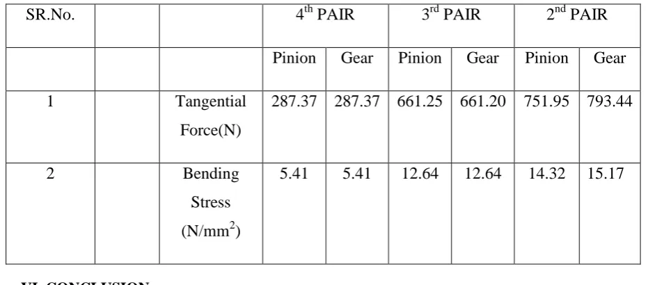
Table 5.1.2 Tangential Force and Bending Stress of gear pair
SR.No.
4
thPAIR
3
rdPAIR
2
ndPAIR
Pinion
Gear
Pinion
Gear
Pinion
Gear
1
Tangential
Force(N)
287.37 287.37 661.25 661.20 751.95 793.44
2
Bending
Stress
(N/mm
2)
5.41
5.41
12.64
12.64
14.32
15.17
VI. CONCLUSION
From table we conclude that,
1. Torque decreases with increase in speed.
2. Bending stress increases with increase in tangential face.
REFERENCES
[1] V. Rajaprabakaran, R.Ashokraj “Spur Gear Tooth Stress Analysis and Stress Reduction” IOSR Journal of
[2] Toni Jabbour , Ghazi Asmar “Tooth stress calculation of metal spur and helical gears” Journal of
Mechanism and Machine Theory 92 June 2015. pp. 375-390.
[3] Miryam B. Sánchez, José I. Pedrero, Miguel Pleguezuelos “Contact stress calculation of high transverse
contact ratio spur and helical gear teeth” Journal of Mechanism and Machine Theory 64 February 2013.
pp. 93-110.
[4] Vishwjeet V.Ambade,. A.V.Vanalkar,.P.R.Gajbhiye “ Involute Gear Tooth Contact And Bending Stress
Analysis” International Journal of Computational Engineering Research, Vol. 03 August 2013,PP 30-36.
[5] Sujit R. Gavhane ,S.B.Naik “Study of Stress Relieving Features in Spur Gear” International Journal of
Emerging Engineering Research and Technology Volume 2, Issue 4, July 2014, PP 209-222.
[6] Mahesh. Badithe, Srimanthula Srikanth, Jithendra Bodapalli “Stree and Reduction analysis of spur gear
![Fig 1.1 Photo-elastic Model of gear tooth [1]](https://thumb-us.123doks.com/thumbv2/123dok_us/9249388.1461468/2.595.237.355.98.176/fig-photo-elastic-model-gear-tooth.webp)