Yu Fai FUNG Im age Processing G roup
D epartm ent o f Physics and A stronom y U niversity College London
Thesis presented for the D egree of
Doctor of Philosophy in the
All rights reserved INFORMATION TO ALL USERS
The qu ality of this repro d u ctio n is d e p e n d e n t upon the q u ality of the copy subm itted. In the unlikely e v e n t that the a u th o r did not send a c o m p le te m anuscript and there are missing pages, these will be note d . Also, if m aterial had to be rem oved,
a n o te will in d ica te the deletion.
uest
ProQuest 10611002
Published by ProQuest LLC(2017). C op yrig ht of the Dissertation is held by the Author.
All rights reserved.
This work is protected against unauthorized copying under Title 17, United States C o d e M icroform Edition © ProQuest LLC.
ProQuest LLC.
789 East Eisenhower Parkway P.O. Box 1346
ABSTRACT
The extraction of useful information from an image involves a series of opera tions, which can be functionally divided into low-level, intermediate-level and high- level processing. Because different amounts of computing power may be demanded by each level, a system which can simultaneously carry out operations at different lev els is desirable. A multi-layer system which embodies both functional and spatial parallelism is envisioned. This thesis describes the development of a three-layer architecture which is designed to tackle vision problems embodying operations in each processing level.
A survey of various multi-layer and multi-processor systems is carried out and a set of guidelines for the design of a multi-layer image processing system is esta blished. The linear array is proposed as a possible basis for multi-layer systems and a significant part of the thesis is concerned with a study of this structure. The CLIP7A system, which is a linear array with 256 processing elements, is examined in depth. The CLEP7A system operates under SIMD control, enhanced by local autonomy. In order to examine the possible benefits of this arrangement, image processing algo rithms which exploit the autonomous functions are implemented. Additionally, the
structural properties of linear arrays are also studied.
Contents
Abstract
Page Number 2
Contents 3
List of Figures 6
List of Tables 10
Acknowledgement 11
C hapter 1: Introduction 12
1.1 Introduction 12
Chapter 2: Multi-layer Image Processing Systems 19
2.1 Introduction 19
2.2 Pyramid Systems 19
2.2.1 Homogeneous Pyramids 21
2.2.2 Heterogeneous Pyramids 27
2.3 Other Multi-processor Systems 32
2.4 Discussion 38
Chapter 3: Linear Arrays 42
3.1 Introduction 42
3.2 Local Autonomy 47
3.3 A Survey of Linear Arrays 48
3.4 Conclusion 67
Chapter 4: The CLIP7A System 71
4.1 Introduction 71
4.2 The CLIP7 Chip 71
4.3 The CLIP7A System 76
4.3.1 The CLIP7A Array 76
4.3.2 System Controller 84
4.3.3 System Software 87
4.4 Summary 93
Chapter 5: Image Processing in the CLIP7A System I 94
5.1 Introduction 94
5.2 Local Data Control 95
5.2.1 Local Addressing 95
5.2.1.1 Multiplication by Lookup Tables 96
5.2.1.2 Skeletonisation by Lookup Table for Binary Images 100
5.2.2.1 Object Identification by a Decision Tree 105 5.2.2.2 Implementation of a Sort Tree in the CLIP7A System 107
5.2.3 Conclusion 113
5.3 Structural Properties of a Linear Array 114
5.3.1 Pre-processing Algorithm 115
5.3.2 Image Transforms 119
5.3.3 Conclusion 125
5.4 Summary 126
Chapter 6: Image Processing in the CLIP7A System II 127
6.1 Introduction 127
6.2 The Second DARPA Benchmark 130
6.2.1 Low-level Processing 132
6.2.2 Intermediate-level Processing 132
6.2.3 High-level Processing 135
6.3 The DARPA Benchmark Problem as a Scene Analysis Problem 136
6.3.1 Low-level Processing 137
6.3.2 Intermediate-level Processing 148
6.3.3 High-level Processing 148
6.4 Conclusion 157
C hapter 7: The Design of a Multi-layer System 161
7.1 Introduction 161
7.2 General Structure of the Multi-layer Unit 161
7.3 Inter-layer Communication Networks 164
7.3.1 Different Connection Methods 165
7.3.2 The Layer I and Layer II Communication Network 167
7.3.2.1 Efficiency Analysis 168
13.2.2 Fault Tolerance 177
1 3 .2 3 Expandability 181
13.2A Conclusion 183
7.3.3 The Layer II and Layer ID Communication Network 183
7.4 Conclusion 187
Chapter 8: The Design of Some System Components 189
8.1 Introduction 189
8.2 The Design of the Linear Arrays 189
8.2.1 The Computing Requirements of the Multi-layer Unit 189
8.2.3 The Layer I Processing Element 197
8.2.4 The Layer II Processing Element 199
8.2.5 The Layer III Processing Element 202
8.3 The Inter-layer Communication Networks 204
8.3.1 The Layer I to Layer II Communication Network 204
8.3.2 The Layer II to Layer III Communication Network 208
8.4 The Controlling Mechanisms and the Controllers 208
8.5 System Software 215
8.6 Estimated Performance of Some Operations 217
8.7 Summary 217
C hapter 9: Summary and Discussion 221
9.1 Summary 221
9.2 Discussion 222
List of Figures
Page Number
Chapter 1
1.1 Flynn Taxonomy 14
1.2 A pipeline architecture 15
Chapter 2
2.1 A pyramid architecture 20
2.2 Block diagram of a MPP PE 22
2.3 AND_Match/OR_Match circuit of the HCL pyramid 24
2.4 Block diagram of the PAPIA PE 26
2.5 Block diagram of the SPHINX PE 26
2.6 An overview of the IUA system 29
2.7 An overview of the Warwick Pyramid Machine 31
2.8 Block diagram of the Connection Machine PE 35
2.9 Block diagram of the PIPE system 35
2.10 Architecture of the PUMPS system 37
Chapter 3
3.1 Bypassing a column of PEs in order to achieve
fault tolerance in a mesh-connected array 44
3.2 Bypassing a PE to achieve fault tolerance in a linear array 44 3.3 Numbering convention of a pixel’s 8 nearest neighbours 46
3.4 Two consecutive 3x3 neighbourhood operators 46
3.5 Block diagram of an AIS 5000 PE 49
3.6 Block diagram of the ASP system 51
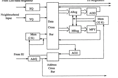
3.7 Block diagram of a CLIP7A PE 52
3.8 Block diagram of a LAP PE 54
3.9 Block diagram of a PICAP3 PME 56
3.10 Block diagram of a PIP PE 58
3.11 Block diagram of a SLAP PE 59
3.12 Block diagram of a SYMBIC PE 61
3.13 Block diagrams of the SYMPATI PEs 63
3.14 Block diagram of a WARP computing unit 65
3.15 Block diagram of a ZMOB PE 66
Chapter 4
4.2 The structure of the binary gate 74
4.3 Different shifting modes of the S-register 74
4.4 The CLIP7A system 77
4.5 Different connection modes of the D-chains 78
4.6 Configurations of the D-chains for data I/O 78
4.7 Different addressing modes of the CLIP7A PE 82
4.8 Emulation of the nearest neighbours connectivity 83
4.9 Block diagram of the CLIP7A controller 85
4.10 An overview of the CLIP7A system software 88
Chapter 5
5.1 The implementation of a lookup table in the local memory 97
5.2 The Arcelli masks 101
5.3 Forming an address from a pixel’s 8 nearest neighbours 101 5.4 New numbering convention for forming an addressing
from a pixel’s neighbours 104
5.5 Image of a gear and its skeleton 104
5.6 Simple objects represented by a tree 106
5.7 A complex object represented by a tree 106
5.8 Maskl 110
5.9 The effect of applying Maskl to an image of hole 110
5.10 Mask2 110
5.11 The tree structure applied to the object identification problem 111
5.12 Images considered in the pre-processing algorithm 116
5.13 Operation sequence of the pre-processing algorithm 118
5.14 Resultant images from different geometric transforms 121
5.15 Performing a rotation by two move operations 122
5.16 Rotation by 10 degrees 122
Chapter 6
6.1 A generalised structure of an integrated vision problem 131
6.2 An intensity image of the benchmark problem 133
6.3 Spatial relationships between two rectangles 133
6.4 Generalised operation sequence of the modified benchmark problem 138
6.5 Locating the edges of overlapping rectangles 140
6.6 The sequence of operations of the labelling algorithm 142
6.7 Good right-angle comer masks and their mask values 143
6.9 Masks represent neither a strong right-angle nor a straight line 145
6.10 Examples of right-angle comers 145
6.11 Examples to demonstrate the right-angle comer detection algorithm 147
6.12 Rectangle parameters defined by 3 contiguous comers 149
6.13 Structure of lookup tables for candidate rectangles’ parameters 150 6.14 Formats employed to represent parameters of a candidate rectangle 152
6.15 The structure of the compatible tables 154
6.16 Addressing the compatible table and retrieving X
coordinates of the centres of the compatible rectangles 156
6.17 An example inter-layer connection network 160
Chapter 7
7.1 An overview of the multi-layer system 162
7.2 Block diagram of the multi-layer unit 162
7.3 Different connection networks 166
7.4 An overview of the layer I and layer II communication network 169
7.5 Format of the symbolic data 170
7.6 A mechanism to achieve fault tolerance
in layer I for the many to many network 179
7.7 An alternative method to achieve fault tolerance
in layer I for the many to many network 179
7.8 A mechanism to achieve fault tolerance
in layer II for the many to many network 180
7.9 Re-directing data paths from a
faulty layer II PE to its nearest neighbours 180
7.10 Achieving fault tolerance by providing a block of spare PEs 182 7.11 Connecting spare elements in the many to one to many network 182 7.12 Adding extra PEs to layer II in the many to one to many network 184 7.13 Block diagram of the inter-layer communication
network between layer II and layer III 186
7.14 Expanding and achieving fault tolerance in the
proposed layer II to layer IH communication network 188
Chapter 8
8.1 Different floating-point formats 191
8.2 Different neighbourhood connectivities for a transputer array 196
8.3 Block diagram of a layer I PE 198
8.5 Block diagram of the binary unit 200
8.6 Block diagram of a layer II PE 201
8.7 Block diagram of a layer m PE 203
8.8 Block diagram of the layer I to layer II communication network 205
8.9 Structure of the decoding logic 206
8.10 An overview of the layer II to layer El communication network 209
8.11 Block diagram of the array controller 212
8.12 Block diagrams of the host and array interface units 213
8.13 Flow of operations in the multi-layer system 214
List of Tables
Page Number Chapter 2
2.1 Parameters of different pyramid systems 33
Chapter 3
3.1 Physical features of different linear arrays 68
Chapter 4
4.1 Characteristics of the CLIP7 chip 72
4.2 Bit assignments for the Condition register 80
Chapter 5
5.1 Execution time for different multiplication algorithms 99
5.2 Timing results for different skeletonisation algorithms 103 5.3 Execution time for the object identification algorithm 112 5.4 Execution time for thinning with and without pre-processing 117
5.5 Timing results for image transforms 123
Chapter 6
6.1 An example of a model data file 134
6.2 Definitions for the rectangle parameters 135
Chapter 8
8.1 Parameters of the 16-bit microprocessors 194
8.2 Truth table for the decoding logic 207
Acknowledgement
I wish to thank my family, especially my parents, for their love and support. I should like to thank my supervisor, Dr. T.J. Fountain, for his encouragement, gui dance and patience. Thanks are also due to members of the Image Processing Group for their help and advice in all aspects.
Chapter 1 Introduction
1.1 Introduction
Im age processing can be applied to a wide range o f problem s including m edical diagnosis, rem ote sensing, robotics and industrial inspection. The ultim ate goal o f im age processing is the extraction o f useful inform ation from a picture w hich can then provide a solution to the target problem . In industrial inspection, for exam ple, im age processing can be used to exam ine com ponents com ing from a conveyor belt with the result that defective objects can be identified and discarded autom atically. A defective object can be identified by m easuring the physical param eters o f objects com ing from the conveyor belt and com paring them with those o f a m odel object. If the difference between the m easured values and the model data exceed a pre-defined threshold level then the object is regarded as defective. In autom atic vehicle guidance, the im age to be processed m ay include different objects, such as other vehicles, traffic lights and pedestrians with the m ovem ent o f the automatic vehicle dependent on the spatial rela tionships between them. In such a situation, the processing operations m ay include first the identification o f the objects and then an evaluation o f their spatial relation ships. The two exam ples given dem onstrate the varying processing requirem ents im posed by different problem s.
A digital im age is organised as a 2-D array o f picture elem ents know n as pixels, the value o f each representing the im age intensity level at that particular location. The size o f an im age and the num ber o f bits used per pixel vary according to the applica
tion. A LA N D S A T (Land Satellite) image [1], for exam ple, is represented by a 2340x3380 array o f pixels, with 7-bit per pixel. A single fram e o f L A N D SA T im agery consists o f a set o f 4 im ages taken at different spectral window s. In C hinese character recognition [2] on the other hand, the size of a character im age is 64x64 pixels and each pixel is represented by a 8-bit integer.
processing task consists of a sequence of operations, with the processing time propor tional to their complexity. Because of the amount of data and the processing opera tions involved, special computing systems embodying different degrees of parallelism have built or proposed since the early 1960s.
Parallel architecture can provide the solution to the enormous computing power demanded by image processing applications and can be classified according to the parallelism employed for the instruction stream and data stream [4]. There are three distinct classes: Single Instruction Multiple Data (SIMD); Multiple Instruction Single Data (MISD); and Multiple Instruction Multiple Data (MIMD). These various control mechanisms can be illustrated graphically as shown in Fig. 1.1. A SIMD machine consists of a single controller issuing instructions to all processing units in the system, which then operate on their own data stored in the processors’ memory. In a MISD system, individual processing elements include a controller, but share a common memory unit. Each processing element operates on the same data set but perform dif ferent operations. The processing element of a MIMD system consists of both a memory unit and a control unit. Individual elements can process different data and perform various operations. There are systems which combine both SIMD and MIMD properties, for example, the PASM [5]. A survey of the various parallel systems is found in [6].
The pipeline architecture (see Fig. 1.2) can be classified as a MISD system, but is always regarded as a special category [7]. A pipeline system consists of a set of pro cessing elements connected in sequence so that data entering the pipeline at the first processing element will leave at the last. The output from one processing element is passed directly to the next element in the pipe. Each element can perform different operations on the data and, if there is a continuous input of data, at one stage all pro cessing elements in the pipeline will be active and the system be in MIMD mode.
CU PE
PE PE PE
(a) SIMD controlling mechanism
M — Memory
PE - Processing Element
CU — Control Unit
PE
CU
PE
CU PE
CU
PE
CU Memory Unit
(b) MISD controlling mechanism
CU CU CU CU
PE PE PE PE
(c) MIMD controlling mechanism
Stagel Stage2 Stage3 Stage4
Data ^Output
CU
CU CU CU
PE PE
PE PE
PE — Processing Element
CU — Control Unit
maps well onto such an organisation. Generally speaking, spatial parallelism employs a large number of processing elements and can be very effective in performing pixel to pixel transformations.
Functional parallelism involves partitioning the com plete process into sub processes and assigning different processing elements to perform various functions. In a functionally parallelised system each PE operates on the entire image data and the result from one is passed to the next for further processing. Functional parallelism maps well onto the pipeline architecture: the FLIP[ 12] is an example in this category ( other pipeline systems are included in surveys presented in [6] and [7]), with its 16 special processors performing different functions. Each processing element is assigned a particular operation on the entire data set and overall system performance is improved by specific tailoring of the processors to the operations.
The above analysis suggests that a system ’s performance could be maximised by exploiting both spatial and functional parallelism and a multi-layer system is thus envisioned. A layer in such a system would embody several processing elements, each operating on its own set of data, with output generated by one layer being passed to the next for further processing. In relation to such a system, two obvious questions are raised: the first concerns the number of layers and the second the number of elements included at each layer. Answers can be obtained by further examination of the image processing problem. Image processing involves a sequence of operations that can be classified into three levels [13], [14]: low, intermediate, and high. There are, however, many other classifications [6], [15] suggesting that the problem could be divided into iconic and symbolic domain only. Low-level processing usually means image to image transformation and may involve algorithms for noise removal and simple feature extraction such as edge detection. Intermediate-level processing operates on symbols extracted from the input image and generates a working description of features represented by them. High-level processing works on features, usually involv
describe the devek
The developm ent of the m ulti-layer system begins with a survey o f existing sys tems. The survey presented in C hapter 2 concentrates on the hardw are features o f such systems and includes a look at the structure o f the processing elem ents; the com m unication network between elem ents and between layers and the controlling m echanism em ployed. The survey will show that existing system s em ploy the mesh- connected array as their basic structure, which maps well to the initial data type - image. H owever, the data types evolved in interm ediate and high level processing (discussed in Chapter 6) may not be effectively represented by a 2-D structure and this leads to the proposal o f using a linear array as an alternative to a 2-D array for the construction o f a m ulti-layer system.
A linear array is cheaper and easier to construct. M ore im portantly it can be adapted to represent data structures evolved at all three levels. G enerally speaking, a linear array with N PEs is em ployed to process an im age with N2pixels. Because the
num ber o f processing elem ents is significantly less than an N2 PE m esh-connected array, the perform ance of a linear array may be affected. Local autonom y provides one possible m echanism to im prove perform ance. In Chapter 3 different aspects o f local autonom y are discussed and a survey o f existing or proposed linear arrays is included. The survey attem pts to establish a better understanding o f linear arrays.
The linear array is chosen as the basic unit for a m ulti-layer system but there are param eters related to its design which are still undefined. This necessitates an investi gation o f the following areas:
1. The effectiveness o f local autonomy;
2. The structural properties o f a linear array;
3. Processing requirem ents at different levels o f operations; and
4. T he relationships between the structure o f the problem and the architecture o f the
In order to carry out the investigation a specific linear array is selected. The one which is chosen is the CLIP7A system, a detailed description o f which is included in Chapter 4. An understanding o f both hardw are and softw are aspects o f the CLIP7A system will assist the read er’s com prehension o f the algorithm s described in chapters 5 and 6.
C hapter 5 describes the algorithm s im plem ented in the CLIP7A system in order
to investigate the structural properties o f a linear array and the effectiveness o f local
autonom y. The results obtained provide inform ation useful for the design o f indivi dual layers o f the m ulti-layer system. In addition, inform ation concerning the design
of the overall structure of the multi-layer system, and the computing requirements at each layer, is obtained by applying the CLIP7A system to an integrated vision prob lem. The algorithms devised p r solving the problem are described in Chapter 6. The
modified DARPA benchmark [63], which embodies processing at three levels, is chosen as an example of a scene analysis problem.
Utilising the results obtained from chapters 5 and 6, the design of a three-layer system is conceived. Chapter 7 describes the overall structure of the system and con centrates on the architecture of the inter-layer communication networks. Chapter 8 is concerned with the design of four major system components. These include the pro cessing elements; the implementation of the inter-layer communication network; the controlling mechanism and the system software.
Chapter 2 *
I
Multi-layer Image Processing Systems
2.1 Introduction
Im age processing is a com putational intensive problem because o f the large quantity o f data and operations involved. Parallelism provides one solution to this
/ ifJ'*' problem and different parallel systems (for exam ple the m esh-connected processor
arrays m entioned in the last chapter) have been built for im age processing^ A parallel system capable o f processing a huge am ount o f data and o f perform ing different operations at the same instant is desirable. A m ulti-layer system , em bodying both spa tial and functional parallelism , satisfies both requirem ents. Spatial parallelism refers to the sy stem ’s ability to process multiple data at the sam e instant, w hilst functional parallelism describes the system ’s ability to perform different functions sim ultane ously.
The developm ent o f a m ulti-layer image processing system m ust begin with a survey o f existing m ulti-layer systems. A pyram id system is a typical m ulti-layer architecture and six different systems are considered in the follow ing sections. The survey exam ines first, the structures of the various processing elem ents em ployed by these system s; second, the connectivity between elem ents in the sam e layer and in consecutive layers and, finally their controlling m echanism s. The objective o f the sur vey is to assess the suitability of the pyramid structure for the envisioned system. T hree different m ulti-processor systems are also included in the survey, each representing a special category o f parallel architecture and their inclusion provides additional inform ation relevant to the developm ent o f the m ulti-layer system.
2.2 Pyramid Systems
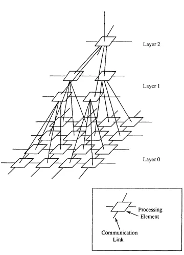
A pyram id system, see Fig. 2.1, is a m ulti-layer architecture em ploying 2-D array as its basic building unit. The base layer (layer 0) o f a system usually haVu'size
equivalent to the input im age, with the next layer having a reduced num ber o f PEs. The system converges until the apex, consisting o f a single elem ent, is reached. The flow o f inform ation usually starts from the base layer and advances tow ards the apex.
In m ost system s, a constant convergence ratio (the num ber o f PEs in layer (N -l) divided by those in layer (N)) is used. Elem ents in a pyram id system are connected both horizontally, within a layer, and vertically, between consecutive layers. F or verti
cal connectivity, the term s father and son are used to describe the physical relationship between the elem ents. W hen two elements in two consecutive layers are connected,
h ~
Layer 0
Processing • Element
Communication Link
Pyram id systems can be divided into tw o different categories: hom ogeneous and heterogeneous. A hom ogeneous pyram id incorporates an identical PE in all its layers w hich is, usually, a simple processor. H eterogeneous pyram ids, on the other hand, em ploy different types o f processing elem ents in different layers with m ore powerful processors generally used in the upper layers.
2.2.1 Homogeneous Pyramids
F our hom ogeneous pyram id systems are included in this survey. A ccording to their inter-layer connectivity, these system s can be sub-divided into tw o classes: quad-pyram id and binary-pyram id. In a quad-pyram id every PE is connected to 4 sons (excepting those in the base layer), w hilst only 2 sons are provided in a binary pyram id. C onvergence ratios for quad-, and binary, pyram ids are 4, and 2, respec tively. H om ogeneous system s include those described below.
GAM Pyramid
The G A M pyram id [16] is a 5 level quad-pyram id developed by the George M ason U niversity. It has a base level o f 16x16 PEs and is devised to process 16x16 pixel binary im ages. Each PE is connected to 4 siblings. The PEs em ployed, as shown in Fig. 2.2, are those used in the M assively Parallel Processor (M PP) [10] developed by the G oodyear Corporation. Each M PP PE includes a set o f 6 1-bit regis ters, a 30-bit shift register, a full adder and m ultiplexed neighbour inputs (4- connected). Each M PP chip em bodies 8 PEs and runs in 10MHz. The M PP pyramid unit is enhanced by 8 Kbits o f RAM and a geom etric unit that provides paths for data transfer between PEs either in the same layer or in the layers above and below. The function of the geom etric unit is to duplicate or select data when it is being transferred between layers due to the num ber o f PEs at each layer being different. D ata is dupli cated when it is moved from a higher to a low er level, w hilst sam pling (or selecting) is required for data passing from a lower to a higher level. There is a feedback output, provided by the M PP chip, that indicates the data bus state o f each PE. The SUM -OR o f all the active PEs is available at each level. The state o f the m ask register, included in each PE, can disable or enable the activity o f that particular PE so that conditional operations can be achieved.
1 -bit
Register
ADDER
Neighbouring
Elements
Data Bus
From PE on Left
To
PE To sum-or
on Right Shift Reg.
RAM
trol except in data transfer between layers. D uring data transfer one layer is specified as the sending agent, whilst another is the receiving agent. The system is program m ed using the G A M pyram id assem bly language, w hich is a com bination o f m icro-code for the pyram id processing elem ents and control unit com m ands.
8x8 PEs. The H CL system is a quad-pyram id and each PE is connected to its 8 nearest neighbours in its own layer.
T he PEs o f the HCL pyram id are very sim ple and are designed to perform two principal operations: A ND _M atch and O R_M atch. The circuitry for the A N D _M atch/O R _M atch logic is depicted in Fig. 2.3. Both operations com pare a specified pattern with a P E ’s neighbouring elem ents, i.e. 13 PEs in total. In the case o f the A N D _M atch, a ‘ 1* is written to a P E ’s accum ulator only if the pattern m atches with all neighbouring elem ents, otherw ise a ‘0 ’ is put to the accum ulator. The O R _M atch operation will generate a ‘ 1’ if the pattern m atches with any of the neigh
bouring elem ents and if not a ‘0 ’ is written to the accum ulator. All operations per
form ed by the pyram id are a com bination o f these operations. Each PE consists o f 3 1-bit registers used for tem porary data storage and an extra 8 K bits o f external m em ory is available. The external m em ory o f the base layer is accessible by the host thus providing the com m unication m edia to the outside world. The control o f the pyram id is SIM D and the host is an IBM PC.
Pyramid Architecture for Parallel Image Analysis (PAPIA)
The PA PIA system [18] is being developed in Italy by a consortium o f universi
ties and industrial com panies. It com prises four units, nam ely the G lobal Control and Scalar Processing Unit, the Pyram id Control U nit, the M ultiprocessor Pyram id Unit (M PU ) and the Active M em ory Unit. O nly the M ultiprocessor Pyram id U nit will be discussed in this section.
paritig w ith using the adder in the M PP alone. The G A M pyram id is under SIM D
con-Hierarchical Cellular Logic (HCL) Pyramid
ii i pi
n2 p2
nl Pi
Result
Or (And)
Or (A nd)
n represents neighbourhood input
p and d sp ecify the control pattern
The MPU is made of 8 planes and arranged as a quad-pyramid, whilst each PE is connected to its 8 nearest neighbours. The PE, as shown in Fig. 2.4, consists of a 1-bit ALU, 256 bits of local memory, near neighbour selection unit, an I/O port and a regis ters and Boolean operators unit. The PE is implemented as a VLSI custom-designed circuit which is fabricated in 4pm Si-gate NMOS technology. Five PEs are integrated into a single chip and are arranged as one father and 4 sons. A PE’s near neighbours are divided into two groups: horizontal and vertical. A PE’s siblings belong to the hor izontal whilst its father and sons are vertical. A PE can only communicate with a sin gle group at each instance and the near neighbour selection unit will choose the proper group. Two shift registers are included in the registers and Boolean operators unit and are used to store temporary data.
Local control is achieved by disabling the activity of a PE according to the value of a mask register. Two masking levels are possible: global and local. When the glo bal masking is set then PEs in the same plane will be disabled, while local masking is effective only when the PE is globally enabled. A feedback signal reflecting the current status of the ALU is provided by each PE. The global state of a plane is avail able by summing all feedback from the PEs by means of an OR gate.
Two clock frequencies are employed; t h ^ y " f o r computation and for data transfer inside, or outside, the pyramid. The clock frequency used for data transfer is faster than the frequency used for computation and is dependent on the speed of the image input/output device. The two clocks overlap so that processing and image input/output can be performed concurrently.
The system can be run in either SIMD, or multi-SIMD, mode. In multi-SIMD mode the pyramid is divided into three sections and planes in each section are under SIMD control of an independent controller.
SPHINX
The SPHINX [19], [20] is being developed by the Paris Sud University and the ETCA Defence research lab of France. It is regarded as a binary pyramid but a dif ferent inter-layer connectivity is employed and each PE is alternately the father of 2 sons of the same X and Y coordinates. The different inter-layer connectivity means that the system consists of 15 layers with a base of 128x128 PEs and each PE is con nected to 4 siblings.
Neighbourhood
Inputs
Near Neighbour Selection
Memory
ALU Registers and
Boolean Operators
Unit
Figure 2.4 Block diagram o f the PAPIA PE
Condition
Reg
To/From
Left Son
To/From Father
To Sum-or
ALU Interrupt Reg
Neighbourhood
Inputs
I/O channel
Data selection logic
To/From
Right Son Memory
The ALU is capable of performing all the 16 logical operations on its two inputs and four arithmetic functions (ADD, SUB, NADD and NSUB) with the carry flag gen erated accordingly. There are 128 bits of internal memory which can be accessed by two independent busses. This allows two read/write operations to be performed simul taneously. There is a bit-serial I/O channel enabling a PE to access external memory. The register set includes a condition register, a carry register and an interrupt register. The condition register is used to inhibit the operation of a PE, according to its content. This masking capability enables the implementation of IF...THEN...ELSE control structures. The carry register is used either as a source or destination for arithmetical operations. The interrupt register is used to centralise a Boolean information on a sin gle layer.
Communication between PEs in different layers is through three registers, one for the father and two for the sons. Reading from, and writing to, those registers is controlled so that data passing between layers is unidirectional. Data transfer between neighbouring PEs in the same layer is through a 4 direction shift register.
The control of the pyramid is multi-SIMD. PEs in the same layer perform the same operation but independent routines can take place concurrently on different layers. The controlling unit in each layer embodies two controllers (high level and low level) which are linked by a FIFO. The dual controller structure is devised to achieve inter-layer synchronisation. The high level controller issues instructions to be per formed by the layer to the FIFO. The instructions will not be executed until a specific condition between the layers is reached. The function of the low-level controller is to monitor the status of a layer and send instructions to that layer only when the condi tion is reached.
2.2.2 Heterogeneous Pyramids
Heterogeneous pyramids employ different processing elements in different layers. In most cases, excluding the host, there are only three layers and the conver gence ratio between consecutive layers is high. Each layer is dedicated to one level of image processing tasks and processing power increases with the level of the pyramid. A description of heterogeneous systems follows.
The Image Understanding Architecture (IUA)
Parallel Processor (CAAPP), the Intermediate Communications Associative Processor (ICAP), and the Symbolic Processing Array (SPA), as shown in Fig. 2.6.
The CAAPP is a 512x512 PE mesh-connected array performing image to image transformations. Each PE includes 5 one-bit registers, an ALU, data routing circuitry and 320 bits of RAM. It is implemented as a custom-designed circuit incorporating 64 PEs in a single chip. The CAAPP is supported by two special features, global sum mary feedback and the Coterie network. The global summary mechanism is an array- wide logical ‘OR’ output indicating whether any CAAPP cells are in a given state. A counting operation which reports the number of cells in a given state is provided. The Coterie network is a switch network enabling processors having similar properties to be grouped together. Processors in a coterie communicate through a bit-wide bus so that groups of processors can execute globally broadcast instructions using locally broadcast data.
The ICAP is a square grid array of 64x64 PEs and will carry out symbolic pro cessing. Each PE consists of a CPU, 256 Kbytes of local RAM, 384 Kbytes of dual ported memory and network communication hardware. The CPU is a Texas Instru ments TMS320C25 16-bit digital signal processor. The function of the dual-ported memory is for communication between the ICAP and the CAAPP, and the SPA. Like the CAAPP, the ICAP provides a global ‘OR’ summary mechanism reflecting the status of the layer. In the prototype system with only 64 PEs, intra-layer communica tion is via a bit-serial crossbar switch network.
The SPA is devised for knowledge-based processing and will consist of 64 powerful processors (the Motorola MC68020 or similar processors) capable of imple menting the LISP language. The detailed architecture of the SPA has not yet been fully defined. A full-connection network is suggested for intra-layer communication. Top-down control of the ICAP by the SPA is also proposed.
The convergence ratio between layers is 64, i.e. each SPA communicating with 64 ICAPs and each ICAP linked to 64 CAAPPs. Communication between layers is through the dual-ported memory of the ICAP. The 384 Kbytes of dual-ported memory is divided into a 256 Kbyte block and a 128 Kbyte block. The 128 Kbyte block is used to communicate with the SPA and the 256 Kbytes memory serves as an interface with 64 CAAPP PEs, that is 32 Kbits per PE.
1 PE
8x8 PE
MIMD Symbolic Processor Array
(SPA)
General Purpose Microprocessors 1 PE
64x64 PE 8x8 PEs
MIMD
1 PE
Intermediate Communications
Associative Processor (ICAP)
Digital Signal Processing Chips
8x8 PEs
512x512 PJ 64x64 PEs
SIM D Content Addressable Array
Parallel Processor (CAAPP)
Bit-serial Processors
branch independently, and globally synchronised at each stage of processing. The CAAPP is under SIMD control of the array control unit.
Warwick Pyramid Machine (WPM)
The WPM [23], [24] is a 4 layer system orientated towards image based prob lems, such as image understanding and computer graphics. The structure of the pyramid machine is divided into a SIMD array, a controller array, a MIMD array and the host, as shown in Fig. 2.7. The convergence ratio between the SIMD array and the controller array is 256, whilst a one to one ratio is used between the controller array and the MIMD array.
The SIMD array is mesh-connected and consists of 128x128 PEs for performing image to image transformations. These are the AMT Distributed Array Processors (DAP). The DAP is a bit-serial processor incorporating a 1-bit ALU and four 1-bit registers. The simplicity of the PE means that 64 PEs are integrated into a single chip. Data storage for the processors is provided by external memory and there are 32 Kbits per processor.
There are 64 elements, arranged in a 8x8 array, in the controller layer. The major function of the PE is to issue instruction streams to the SIMD array, therefore each PE consists of a micro-instruction sequencer (an AMD29331). Other components utilised in the PE include a micro-programmable 16-bit processor (AMD29116), 16K x 68bit micro-code store and 2 Kwords dual-ported memory. The dual-ported memory is used as a communication channel between the controller and the processor in the MIMD array.
The MIMD layer is a 8x8 PE transputer array for symbolic processing. The tran sputer used is the T414 32-bit processor, each associates with 256 Kbytes of external memory. Each transputer is connected to its four nearest neighbours and communi cates with a single controller in the controller array.
The host is used as an user interface and also provides mass storage for the sys tem. Software facilities, such as text editor and programming language compiler, are supported.
Sun Workstation
Host
8x8 array o f Symbolic Processors (MIMD)
Transputer Array
8x8 array o f Controllers Intermediate LeveJ
Processors
DAP Pixel
Processing Elements
128x128 array o f
SIMD bit-serial 16x16
PEs Processors
the micro-code store in the controller and are broadcast to all PEs within a cluster. Elements in the MIMD layer can also direct the operations of a cluster by calling up an instruction through a software protocol using the dual-ported memory in a con troller.
Communication between a controller and the SIMD PEs in the cluster is through a special register mapped into the register space of the controller. Additionally, a counting mechanism, reporting the number of SIMD processing elements of a given status, is provided.
Programming of the system is through two programming languages, the Parallel C and cluster assembly language. The Parallel C is used to programme the transputer array. The cluster assembly language is for the programming of both the controller and the SIMD PEs in a cluster.
2.3 Other Multi-processor Systems
Table 2.1 summarises the properties and features of the machines described in the previous section. In addition to the above pyramid systems, there are three sys tems, namely the Connection Machine [25], [26], the PIPE [27], and the PUMPS [28], which are included in the following discussion. Each system represents a class of multi-processor architecture. Useful information relevant to the development of a multi-layer system will be extracted from these architectures. The discussion will concentrate on the important features of each system and details of the processing ele ments will not be included.
Connection Machine
System GAM HCL PAPIA SPHINX IUA WPM
Type Ho
quad
Ho quad
Ho quad
Ho binary
He He
Number
o f layers 5 4 8 15 3 4
Size o f
base layer 16x16 8x8 128x128 128x128 512x512 128x128
Layer ralio 1:4 1:4 1:4 1:2 1:64 1:256 1:1
ALU 1-bit Special functions
1-bit 1-bit 1-bit
16-bit 32-bit
1-bit 16-bit 32-bit
Conlrol Mode SIMD SIMD Multi-SIMD Multi-SIMD SIMD and MIMD
Multi-SIMD and MIMD
Ho == Homogeneous and He == Heterogeneous
The most important feature of the Connection Machine is its inter-element com munication mechanisms including both a router network and the NEWS grid. The router network enables a processor to communicate with any other processor in the system. There is one router per 16 PEs which is incorporated in the processor chip. The routers form a 12 dimensional hypercube network [29] meaning that each router is connected to 12 other routers. Each router is given a unique number and two routers, e.g. i and j, are connected if and only if li - jl = 2* for some integer k. A mes sage originating from a PE may pass through a series of routers before reaching its destination. To achieve this, each router embodies an ALU to evaluate the proper router location. The NEWS (North, East, West, South) grid allows processors to exchange data between PEs which are physically connected. The direction to which data will be received, or transmitted, via the NEWS grid is determined globally (i.e. all the PEs will send, or receive, data from the same direction). Communication through the NEWS grid is faster than the router network if the destination for the data is a PE’s four nearest neighbours.
Pipeline Image-Processing Engine (PIPE)
The PIPE system is a multistage pipeline architecture designed by the National Bureau of Standard (USA) for performing low-level image processing at TV-field rate. The system is built up in stages, as shown in Fig. 2.9, and excepting the input stage and the output stage, other processing stages are identical. The input stage con tains two image buffers, used to store images captured from the input devices, whilst the output stage is employed to interface with the output devices. Between the input stage and the output stage are the Modular Processing Stages (MPS) which are responsible for the processing of the input image.
The most important features of the PIPE system are its multi-input and multi output data streams, staged operation sequence and parallel neighbourhood operators. As shown in Fig. 2.9, the three data streams carrying data representing three 8-bit 256x256 pixel images are the forward path, backward path and the recursive path. The forward path is for passing data from one MPS to the next in the pipeline whilst the backward path passes data in the opposite direction. The recursive path conveys processed data back to a MPS. The advantage of such an arrangement is that it allows image data to participate in temporal, as well as spatial, neighbourhood operations.
Memory
ALU
Register set
To Router
Figure 2.8 Block diagram o f the Connection Machine PE
Processing Stages
Recursive Path
Forward Path
Backward Path
Modular Processing Stage
operations, the three data streams are combined and stored in an image buffer. Neigh bourhood operations, the second stage, follows. There are two neighbourhood opera tors which can carry out either arithmetic or Boolean operations in a 3x3 neighbour hood in parallel. Both operators receive identical input data but can perform different operations. Before the data leave the MPS, further transformation or arithmetic opera tions are possible. In the final stage, operations are applied to either outputs from the two neighbourhood operators by one of two programmable functions: a lookup table mapping function and an ALU performing arithmetic function. The data stream aris ing from either of these operations can be selected to become the forward path, back ward path or the recursive path. As each MPS operates in parallel, real-time low-level processing is achieved.
PUMPS
The PUMPS system, proposed by Briggs et al of the Purdue University, is designed as an integrated image analysis and image database processing system. The structure of the system, as shown in Fig. 2.10, can be divided into an image processing and analysis unit, and the Database Machine. The sections are linked by data busses and shared memory.
The image processing and analysis unit embodies two kinds of processing ele ments namely the Task Processing Units (TPUs) and the Peripheral Processors and VLSI Units (PPVUs). Each TPU consists of a microprocessor and memory, and can perform three functions:
1. Dispatch and initiate PPVU tasks; 2. Execution of purely sequential tasks;
3. Participation in MIMD processes and running the operating system.
Communication between the TPUs is via the Task Processor Communications (TPC) Bus.
Imagc P rocessing and A nalysis Unit
Shared Memory
Database M achine
Database
M anagem ent
System Processor Memory
Interconnection Network Shared
Cache
TPC Bus
TPU TPU TPU
Special Resource
Arbitration Network
00
Data M odules
Peripheral Processors and VLSI units
used as a data transfer and storage medium. Blocks of data can be transferred from any TPU to the SM through the Processor-Memory Interconnection Network. The Shared Cache is employed as a temporary storage for data which is operated on by the TPUs because of its high speed. The Shared Memory is also used to exchange data between the Database Machine and the image processing and analysis unit.
The Database Machine is designed to support high speed image retrieval from the storage device by enabling a user to specify relational information of an image. To achieve such a requirement, the Database Machine supports both high-level data base functions and low-level image processing operations. The major components in the Database Machine are the relational database system for images (REDI) and the relational database machine (DIALOG). The REDI supports a relational query language which enables a user to select an image from the database by specifying the spatial relationships between objects in an image. The DIALOG performs the process ing required by the enquiry and embodies identical data modules operating in parallel. Each data module consists of an image storage device, a disk, and special hardware to perform the particular database, or image, functions. This currently includes join,
selection and histogramming. n n.
In the above section ti-layer and multi-processor systi ve been studied. Each system incorporates one or more unique features, each of which improves the system performance in specific circumstance. A brief summary is given here.
Pyramid systems can be divided into homogeneous and heterogeneous systems. A homogeneous pyramid employs one type of processing element at all layers. The systems studied have the following common features:
1. Size of base level equals to the input image so that each pixel can be processed by one PE.
2. A very simple element is used, usually single bit, meaning that several PEs can be housed in a chip (this, in return, reducing the number of chips employed in the overall system).
- 3 9
-system.
H eterogeneous system s em ploy different processing elem ents at different layers. G enerally speaking, a layer in a heterogeneous pyram id perform s a particular level of processing tasks and there are only three layers in a system (excluding the host). The two system s presented also include the follow ing com m on features:
1. Base layer has a size equal to that o f the input im age and a sim ple PE, with 1-bit A LU , is em ployed
2. D ifferent processing elem ents are em ployed at different layers, the com plexity increasing with the level o f the pyramid.
3. Shared m em ory (dual-ported) is used as a com m unication m edium between
4. Top-dow n control, m eaning that elem ents in one layer can instruct elem ents in the layer below, is allowed.
The controlling m echanism used by the heterogeneous system s is m ore com plex. Ele m ents in the base layer can be operated in either SIM D, or m ulti-SIM D , mode. In the latter case, elem ents in the m iddle layer act as the controller for the base layer. The upper layers are under M IM D control.
T he survey dem onstrated that pyram id architecture from certain shortcom ings with the im plication that it is not suitable for the envisioned system. As discussed in C hapter 1, the envisioned system will em body three layers, with each layer perform ing different kinds o f com putation. H om ogeneous pyram ids usually con sist o f (log2N + 1 ) layers, w hen there are N 2 PEs in the base layer, and are m ost suit able for perform ing m ulti-resolution processing [30]. H om ogeneous pyram ids, under SIM D control, cannot provide functional parallelism .
In com parison, the heterogeneous approach seem s m ore suited for the envisaged system , but several design problem s arise. In order to achieve efficient im age to image transform ations (low -level processing), a one PE per pixel m esh-connected array serves as the base layer. The convergence ratio between layers is high (64 and 256 for the two system s), so a large quantity o f com m unication and control channels is required between elem ents in different layers. This, in turn, increases the com plexity o f a system. Even though a high convergence ratio is applied, the num ber of PEs available at the m iddle and top layers is still high. As pow erful com puting units (16-
bit and 32-bit devices) are em ployed by these layers, the cost o f a heterogeneous pyram id is likely to be high. A nother problem relates to the program m ing o f the sys tem. D ifferent com puting units are incorporated in different layers and the basic
program m ing requirem ents for them will be different. It is, therefore, m ore difficult to
develop the system software.
Im ages are the first data type to be processed in any vision system , m aking the m esh-connected array an obvious choice as the basic architectural unit o f a m ulti-layer system. H ow ever, in other levels o f processing, different data types, for exam ple sym bols and feature lists, are involved and these may not m ap w ell onto the 2-D array. This suggests other architecture(s) should be provided in the m iddle and top layers, or alternatively that an architecture which can be adopted for different data types should be used as the basic structure. Linear array is one such alternative and will be exam ined in the next chapter but before that, the properties o f other m ulti-processor sys
tems are studied.
O ther m ulti-processor systems all have their own special features w hich m ay be adopted by the envisioned system. First, the Connection M achine w hich, as its name im plies, em phasises the im portance o f inter-elem ent com m unication by providing a 12 dim ensional hypercube router network. The system can be visualised as a tw o layer m achine, with its PEs in the base layer and the router netw ork as the second layer. D ata from any PE can be transferred through the router network to any other PE within the system.
The special design feature in the PIPE system is the m ulti-input and m ulti-output data stream s. The three input data streams, forward, backw ard and recursive provide tem poral, as well as spatial, inform ation. It is, however, possible to interpret the m ulti ple data stream s as another form of inter-elem ent connectivity. A nother special pro perty is the parallelism perm itted within each processing stage. Three different opera tions can be applied to the inputs in parallel and two different neighbourhood opera tions can be perform ed at the same instant.
The PUM PS system dem onstrates a rather direct approach to the construction of a highly parallel system. In the proposed system architecture, different com puting units such as pipeline processors and a FFT processor, can be incorporated in the sys tem. There is also a special database m achine for image. C om m unication betw een ele
m ents is via switching networks or shared memory. The draw backs o f the system will be its cost and com plexity: the cost is proportional to the num ber o f com ponents included and the different controlling m echanism s required by the various com ponents im pose a penalty on developm ent of system software.
- 4 2
-Chapter 3 Linear Arrays
3.1 Introduction
T he objective o f this thesis is to develop a m ulti-layer system consisting o f three layers perform ing low, interm ediate and high level processing independently. The envisioned system can be constructed by adopting the heterogeneous pyram id archi tecture but this does suffer from certain shortcom ings including cost, com plexity and program m ing m ethodology. A dditionally, the data types evolved in higher processing levels, unlike an image, do not have an intrinsic structure; this suggests that elem ents in those levels do not need to be arranged as 2-D arrays and linear arrays serve as one alternative. A s stated by Basille et al [15], and reflected by the m any linear im age pro cessing system s being built or proposed (see Section 3.3), linear array can be applied to both im age based and non-im age based processing. It is, therefore, possible to em ploy the linear array as the basic architectural unit for the envisaged system.
T he linear structure is chosen because it has (as described in [31]) the following advantages:
1. Flexibility
The reduction in the num ber o f PEs em bodied in a linear array implies that each PE can have any desired degree o f autonom y (this is treated in Section 3.2). This
flexibility w idens the operational scope o f an array.
2. Ease o f construction
In a linear array each elem ent is (usually) connected to its left and right neigh bours in the string. This facilitates extension to a larger num ber of processors.
The physical im plem entation o f a linear array is easier than that of a m esh-connected array due to the sim pler connectivity em ployed. Each elem ent is connected to its left and right neighbours and this connection netw ork is quite easy to retain physically,
w hilst in a m esh-connected array, nearest-neighbours connectivity is difficult to retain physically and neighbourhood connections can often only be achieved via external cables. In the context o f the construction o f a m ulti-layer system , a m ulti-linear array system is a 2-D structure, which is difficult to build because o f the inter-layer connec tion netw ork. In com parison with the 3-D structure o f a pyram id system, how ever, a m ulti-linear array system is much easier to construct. In m any cases, a linear array
with N PEs is em ployed to process N 2 pixel im ages, im plying a m uch sm aller num ber o f PEs available in the base layer than in the pyram id system s. This leads to a reduc
base and intermediate layers, implying that a smaller number of PEs can be used in the intermediate layer and a similar effect applied to the top layer as well. As a result, both the cost and complexity of the multi-layer system will be less than that of the heterogeneous pyramid approach.
Linear arrays have other advantages including expandability and fault tolerance, the latter being an important factor that should be included in any computer system. In a multi-element parallel computing system it is possible to embody spare processing elements in the system in order to maintain the functional size of an array when ele ments fail. Elements in an array are connected to their neighbours and it is important to retain such connectivity, especially in the low-level layer, after a faulty element is switched off. In a 2-D array, the re-establishment of the near neighbours connection requires a very complex switching network, as described in [32]. One strategy by which the switching network can be avoided involves switching off the whole column or row that contains the faulty element. In this case, only the communication channel in one direction needs to be re-connected, as shown in Fig. 3.1. This implies that extra columns/rows of processing elements are needed, but, for a linear array, the communi cation between elements is along a single direction and the switching off of a faulty element requires the re-establishment of one communication channel only, as shown in Fig. 3.2. Individual faulty elements can be bypassed and replaced by spare process ing elements connected to the end of the array.
A linear array can be expanded by the addition of extra elements at the end of the array due to its one dimensional property and simple neighbourhood connectivity. This property is valuable for the second and third layers of the system because the amount of data involved in those layers is variable (see Chapter 6). Expanding an array to improve parallelism may be necessary and this will be discussed in Chapter 7. The rest of this section will demonstrate how a linear array can be applied to different levels of processing operations.
In low-level processing, the 2-D structure of an image can easily map into a linear structure. For example, a linear array with N elements can process images with
A column of PEs bypassed A column o f spare PEs
^ Faulty element
A PE and its communication links
Figure 3.1 Bypassing a column of PEs in order to achieve fault tolerance in a mesh-connected array
a
-\
Bypassing a PE
H
\
Spare PE
Faulty PE A PE and its communication links
neighbours. D uring a neighbourhood operation, tw o consecutive w indow s have six pixels in com m on, as depicted in Fig. 3.4, and consequently only three new pixel values are needed in order to evaluate the result for the second w indow . Tw o o f the three pixels are located in the neighbouring PEs and can be extracted easily with two shift operations. The third pixel com es from the P E ’s local m em ory.
As described in Chapter 1, im ages are processed by the low -level array, w hilst the interm ediate layer operates on sym bolic data. It is, therefore, necessary to transform inform ation conveyed by an im age, after low -level processing, into a dif ferent form at (symbolic) before interm ediate-level processing proceeds. A linear array can also easily re-arrange inform ation carried by an im age to a sym bolic data m atrix because each PE can access any pixels residing in its local m em ory in a read operation. This simplifies the process o f gathering inform ation from different loca tions in an im age in com parison with the m any shift operations required to transfer data betw een PEs in the same colum n in a m esh-connected array. A PE can then extract the useful inform ation, which will be stored in the local m em ory. In such an arrangem ent, parts o f a P E ’s local m em ory carry im age-based inform ation (pixels), w hilst sym bolic data is available from other parts. O nly the sym bolic data is transferred to the interm ediate layer and, because, in m ost cases, the quantity o f sym bolic data is less than the num ber o f pixels in an im age, this in turn reduces the rate of com m unication between the two layers.
It is difficult to indicate the effectiveness o f a linear array for interm ediate-level and high-level processing, due to the absence o f a consistent data structure involved at these levels. T hat the data structures which evolve depend on the particular vision problem will be dem onstrated in Chapter 6, but in general a variable appearing in interm ediate-level or high-level processing can be expressed as a string of data [31]
rather than as a single pixel value. Each elem ent in a linear array can either process data belonging to the same string or each elem ent can operate on a section o f one string so that parallelism can be achieved.
Direction
Relative to Pixel X
North West North North East East South East South South West West
Figure 3.3 Numbering convention of a pixel’s 8 nearest neigbours
1 2 3
8 X 4
7 6 5
Code 1 2 3 4 5 6 7 8 A Previous Nearest Neighbours i i
i A B
---1
i i C «
---1- .
D E F
G H I
J K L
T
Current
Nearest
Neighbour
3.2 Local Autonomy
In Section 3.1, the linear array was proposed as the basic structure for a multi layer architecture and its suitability is supported by the fact that a linear array can be applied to processing at all levels and is relatively easy to build. By employing a smaller number of processing elements in the system its performance may obviously be affected, especially in the low-level operations: it is therefore desirable that the performance be improved through other methods. The introduction of local autonomy to elements in an array is one such solution.
As discussed in [33], there are six levels of autonomy available to each processor in an array comprising activity, data, function, operation, sequencing, and partitioning.
1. Local activity control is the ability to determine locally whether or not each pro cessor is active.
2. Local data control applies to processors which can locally select the source and destination of the data used by a globally-determined process. Source and desti nation can be located in the local memory or a neighbouring element.
3. Local function control allows a processor to select which function is to be per formed under pre-determined conditions.
4. Local algorithm control enables a processor to execute an algorithm resident in the local programme store. The sequencing of these stores is under global con trol, thereby ensuring synchronous operation of the array.
5. Local sequencing control is an enhancement of local algorithm control. Each processor can sequence its own programme memory which stores the code of the algorithms. Under this mode of autonomy, synchronisation between elements is no longer automatic, but must be ensured by appropriate handshaking operations. 6. Local partition control is the highest level of local autonomy. At this level, a pro cessor transfers programme segments to other processors in order to share its work load with other elements.
In order to incorporate the different levels of autonomy in a system, modifications to the structure of the processors are required. Estimates for the cost, performance, and processor complexity imposed by different degrees of autonomy are found in [33].