SYSTEM USING P&O MPPT ALGORITHM
Sudhakar Babu Illa1, G. V. Siva Krishna Rao21. INTRODUCTION
Due to the shortage of fossil fuels and environmental problems caused by conventional power generation, renewable energy, particularly solar energy, has become very popular. Solar-electric-energy demand has grown consistently by 20%–25% per annum over the past 20 years [1], and the growth is mostly in grid-connected applications. Single phase rooftop PV systems are major research area for grid integration, since these sources have huge opportunity of generation near load terminal [2]. In a grid-connected PV system, control objectives are met by a strategy using a pulse width modulation (PWM) scheme based on two cascaded control loops [3]. The two cascaded control loops consist of an outer voltage control loop to settle the PV array at the MPP, and an inner current control loop to establish the duty ratio for the generation of a sinusoidal output current, which is in phase with the grid voltage [4]. The current loop is also responsible for power quality issues and current protection for which harmonic compensations and dynamics are the important properties of the current controller. Linear controllers such as proportional-integral (PI), hysteresis, and model predictive controllers are presented in [5]–[8], which provide satisfactory operation over a fixed set of operating points as the system is linearized at an equilibrium point. Since the PV source exhibits a strongly nonlinear electrical behaviour due to the variation of solar irradiance and nonlinear switching functions of inverters. As linear controllers for nonlinear PV systems affects all the variables in the system and the electrical characteristics of the PV source are time varying, the system is not linearizable around a unique operating point or trajectory to achieve a good performance over a wide variation in atmospheric conditions. With PV sources connected at the DC side of the inverter, it is utmost essential to fetch maximum power from the source to make the system efficient. Out of different algorithm to track maximum power point (MPP) such as perturb and observe (P&O), Incremental Conductance (IC) etc., IC based method provides fast dynamics and control over fast changing insulation condition [6] [8]. In this paper a new SRF theory has been proposed for single phase roof top inverter. The inverter controller is based on the current driven PWM based voltage controller which is capable of both current and voltage controller. PI controller is used for maintaining DC link voltage and by maintains DC voltage constant during operations, is ensured the total power being generated by PV across the dc bus by the inverter by the grid. And in order to boost up the dc Voltage DC-DC boost converter is connected between PV system and Inverter The Rooftop PV inverter is modelled using MATLAB/SIMULINK software and results sows the effectiveness of the system.
2. SYSTEM CONFIGURATION
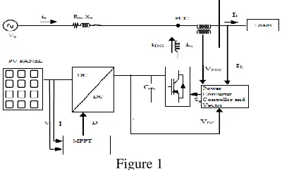
Figure 1 shows the Schematic of the implementing system. It consists of Single phase Grid and Load. PV panel and this panel is connected to the DC-DC converter and there is a Capacitor placed after the Dc-dc converter which acts as a Dc link Voltage Source. The Single phase is connected in between the Single phase and Load at the point of PCC (Point of Common Coupling) with the help of the Injection transformer. Incremental Conductance based MPPT is used and its output is feed to DC-DC converter in order to Dc link constant. The direct voltage controlled current driven by Voltage Source Converter keeps the voltage constant across the tank capacitor by regulating the power evacuation via voltage control. The harmonics at the PCC can be filtered out by the proper design of LCL filter at the output of VSC. The conventional 3 phase SRF theory is modified to suit the single phase system. The modified SRF theory is applied to decompose the load current to generate the reference reactive power current command. Reference for the real current component is obtained by applying PI controller on the error between measured voltage and the reference voltage.
1 Department of Electrical Engineering, Andhra University College of Engineering, Visakhapatnam, Andhra Pradesh, India 2 Department of Electrical Engineering, Andhra University College of Engineering, Visakhapatnam, Andhra Pradesh, India
Abstract— This paper presents a modular photovoltaic (PV) inverter for single phase grid-connected applications this inverter helps to improve the low THD sinusoidal line compensating currents and to improve the reactive power Compensation. The roof top PV system is connected to grid and works with a battery back for off grids system to realize better utilization of PV modules and maximize the solar energy extraction, and PV power is being tracked with An incremental conductance maximum power point tracking. Synchronous reference Frame theory based PWM is used for Controlling of Inverter. PI controller is used controller of DC link voltage. This system is implemented using Matlab/simulink software and results show the effectiveness of the system.
3. MODELLING OF PV
PV array is a p-n junction semiconductor, used to convert sunlight into electrical energy. When the incoming solar energy exceeds the band-gap energy of the module, photons are absorbed by materials to produce electricity. The cells in the PV array are tied in series or parallel and the electrical power of the PV array depends upon the solar irradiance, panel temperature and the operating current and voltage relationship. The current voltage relationship, which is the I-V characteristic of the PV array is a complex and non-linear function. The following exponential model is used to describe and predict the behaviour of our proposed photovoltaic module. According to this model, maximum power, Pmax equals (1)
(1)
(2)
(3)
Where ISC is the short circuit current, VOC is the open circuit voltage, IOP is the optimal current and IOP is the optimal voltage. Solving equation (1) for b and taking into account that b is very small; b can be estimated by equation (2). This value is distinct and unique for every solar panel and does not fluctuate with changes in irradiance and solar cell temperature. Thus for a particular irradiance level and cell temperature, if ISC, VOC, IOP and VOP are found for a given solar panel, the value of b can be achieved. By using the value of b in the exponential model, an accurate representation of the voltage and current characteristics of the panel can be obtained. Using the value of b, the optimal resistance Rop can also be found, which is the load resistance at which the photovoltaic panel transfers Pmax to the load.
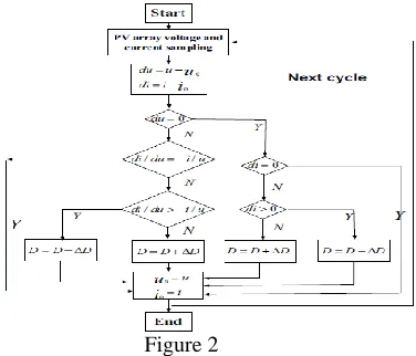
3.1 Maximum Power Point Tracking (MPPT)
Figure 2
3.2 Control System
Figure 3 shows the control system of the proposed circuit. Here the Grid current is converted in to alpha beta components using Clark’s transformation and same is done for load currents also. Here in order to find sin and cos components of for SRF method single phase discrete PLL is used. For the application of modified SRF theory to single phase system, phase voltage or current is taken as alpha (α) component in α-β frame (stationary frame of reference), and by introducing phase delay of 90° to alpha components, β component is obtained as shown in figure 3. The obtained are passed through low pass filter and the reference currents are obtained. Vdc from the capacitor and reference Vdc is obtained and both are compared using addition and fed to PI controller. Here pi controller is used to control the dc link voltage and the Error current is obtained and these currents are compared with the currents obtained from low pass filter and are fed to PI controller in order to get reference Error currents and then these are fed to PWM generator and PWM used here is sinusoidal pulse width modulation and these pulses are fed to VSI (Voltage source inverter).
Figure 3
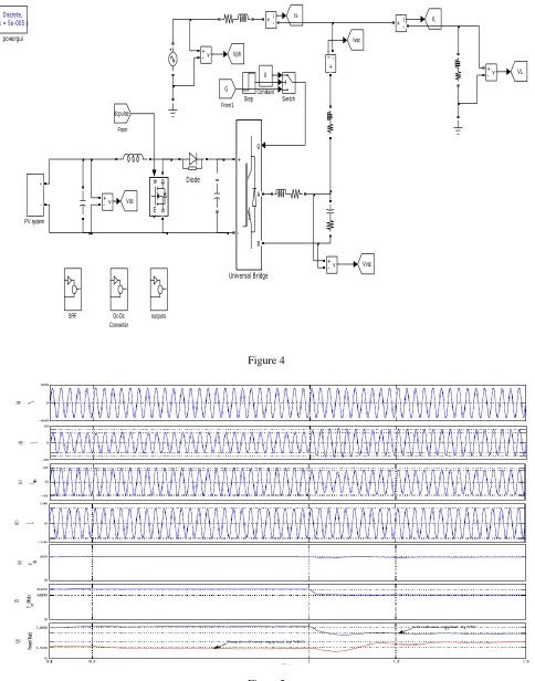
3.3 Matlab Simulation Implementation
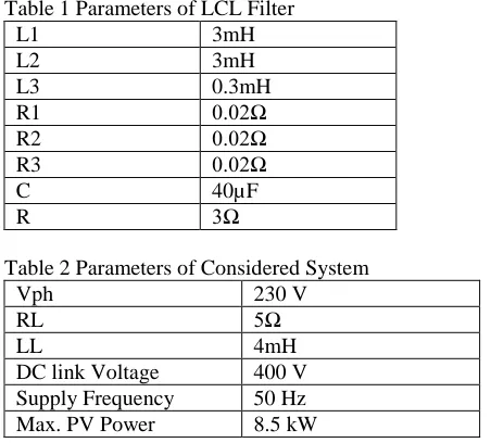
Vph 230 V
RL 5Ω
LL 4mH
DC link Voltage 400 V Supply Frequency 50 Hz
Max. PV Power 8.5 kW
3.4 Performance Evaluation
outputs v
+
-v + -g
A
B +
-Universal Bridge
SRF
+
-PV system
g
m
D
S
Vdc
Vvsc From1
dcpulse
From
Diode
Dc-Dc Converter
Figure 4
Figure 5 4. CONCLUSION
[4] [4] G. Amani, Shyam Kumar, Ch. Mohan Rao“ Modelling and analysis of Robust Non Linear Controller of Three Phase Grid connected System under Structured Uncertainties”, International Journal & Magazine of Engineering, Technology, Management and Research, Vol. No. 2, Issue 7,PP 2093-2097, 2015.
[5] [5] S.Mekhilef, "Performance of grid connected inverter with maximum power point tracker and power factor control," International Journal of Power
Electronics, vol. 1, pp. 49-62, 2008.
[6] [6] S.Mekh Femia, N.; Petrone, G.; Spagnuolo, G.; Vitelli, M., “A Technique for Improving P&O MPPT Performances of Double-Stage
Grid-Connected Photovoltaic Systems,” IEEE Trans. Industrial Electronics, vol. 56, pp. 4473-4482, 2009.
[7] [7] M. G. Villalava,j. r. Gazoli,E. Ruppert F., “Modelling and circuit –based simulation of Photovoltaic arrays” Brazilian Journal of Power
Electronics,vol 14,no.4,pp. 35-45, 2009.