Abstract— This paper presents an adaptive algorithm that is considered as a modification to the Block Linear Equalizer which is used with Block Data Transmission Systems. The two main factors that influence the noise performance of the Block Data Transmission System are the distortion introduced by the channel and the block size. The proposed algorithm considerably improves the noise performance and hence the transmission efficiency of the system by adaptively reducing the block size of the transmitted signal-elements when the distortion introduced by the channel is high and increasing the same when the channel distortion is low. This advantage is achieved with only a slight increase in the equipment complexity.
Index Term— Wireless, Block transmission, Channel distortion,Equalizer
I. INTRODUCTION
In the study of detection processes for distorted digital signals, techniques of both linear and nonlinear equalization of the channel have been widely studied, The non-linear equalization of the channel usually gives a better tolerance to additive white Gaussian noise than linear equalization , normally requiring a lower average signal to noise power ratio for a given error rate. An even better tolerance to noise can be achieved through the use of more sophisticated detection processes which do not equalize the channel. Many of these
processes, however, involve considerable equipment
complexity [1-4].
An interesting technique called the Block Data Transmission system (BDTS) has recently been proposed which for certain applications can achieve a similar standard of performance as the more sophisticated processes just mentioned, but with relatively simple equipment [5-8]. The system is a synchronous serial data transmission system and employs transmission of alternating blocks of data and training/zero valued symbols. In contrast to the recursive symbol-by-symbol detection approach usually employed, each data block is here detected as a unit. The Block Linear Equalizer (BLE) and Block Decision Feed Back Equalizer (BDFE) have been designed for the system and the system has applications in
Farid Ghani is with the Universiti Malaysia Perlis, 01000, Kangar, Perlis, Malaysia; (phone: + 604-9853944; fax: +604-9851695; e-mail:
[email protected] ; [email protected] ) Mutamed Khatib is with the College of Engineering and Technology Palestine Technical University-Kadoorie (PTU) Tul-Karem, Palestine
wireless local loop, wireless LAN’s and indoor communications in general [6-8]. Techniques for estimating the channel characteristics have also been proposed for implementing BLE in an adaptive manner [9-12].
Block Data Transmission System mentioned above has some
useful advantages over systems with continuous transmission.
Firstly, exact equalization of the channel is, in every case,
achieved. Secondly, complete loss of signal cannot result from
an unfortunate combination of signal-element values and the channel impulse response. Thirdly, there are no error extension effects from one block of elements to the next, regardless of the detection process used. Finally, detection process achieving a high tolerance to additive Gaussian noise can be implemented quite simply [5-8, 11].
Assuming that there are m signal-elements in a group and g training/zero elements then in the BDTS adjacent blocks of m signal-elements at the transmitter, are separated by g training/zero elements which carry no information. (m+g)T seconds are required to transmit the information carried by the m signal-elements of a group, where 1/T is the element transmission rate. If groups of signal.-elements are replaced by a continuous stream of elements without the g training/zero, then for the same information rate, m signal-elements must now be transmitted, with no gaps, over (m+g)T seconds. This means that the element transmission rate in the equivalent continuous transmission, is reduced from 1/T to 1 /T' where T’ = (m+g/m)T. Thus for a given information rate, the bandwidth required in the case of BDTS is wider than that required for the continuous system. This reduces the tolerance to noise of the BDTS and partly offsets the basic advantages gained by the arrangement.
In order to improve the tolerance to noise of the BDTS, the value of m should be kept large compared to g the number of training/zero elements. However, it is shown that when the channel introduces severe amplitude distortion the tolerance to noise of the BDTS decreases as the group size m is increased. Thus in order to utilize the advantages offered by BDTS the group size of the block should be changed in an adaptive manner. When the distortion in the channel increases the group size should be reduced and when the distortion in the channel decreases the group size may be increased.
This paper presents an adaptive algorithm where the group size m of the transmitted signal-elements is changed adaptively depending on the estimates of the channel impulse response. The resulting block linear equalizer is called the Adaptive Block Linear Equalizer (ABLE). Results of computer simulation show that ABLE achieves considerable advantage in tolerance to noise over the BLE together with
Adaptive Block Linear Equalizer for Block Data
Transmission Systems
higher transmission efficiency. These advantages are achieved with only a slight increase in equipment complexity.
This paper is organized as follows. In Section II, a brief description of BLE is given. The design and analysis of the adaptive algorithm is presented in Section III. In Section IV results of computer simulation are presented and the performance of BDTS with and without the proposed algorithm is compared. Vectors and matrices are represented by block capital letters.
II. BLOCKLINEAREQUALIZER
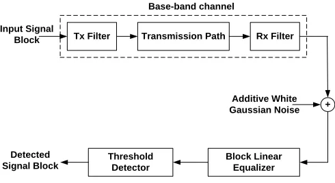
Fig. 1 shows the model of the data transmission system
considered. Each impulse si δ (t-iT) at the input to the channel
is the corresponding input signal-element and it may be either binary or multilevel. The signal elements are assumed to be antipodal and statistically independent.
Tx Filter
Block Linear Equalizer Threshold
Detector
Transmission Path Rx Filter
+ Additive White Gaussian Noise Base-band channel
Input Signal Block
Detected Signal Block
Fig. 1. Model of the block transmission system
The linear baseband channel has an impulse response y(t) and includes all transmitter and receiver filters used for pulse shaping and linear modulation and demodulation. The impulse response h(t) of the transmitter and receiver filters in cascade is assumed to be such that h(0) = 1 and h(iT) = 0 for all nonzero integer values of i. This impulse response is achieved
by using the same transfer function B(f) = H(f)½ for the
transmitter and receiver filters, where
1 1 1
T(1 cos(2 ft)) - f
H(f ) 2 T T
0 else where
(1)
White Gaussian noise is introduced at the output of the transmission path. The noise has zero mean and a two sided
power spectral density of σ2, giving the zero mean Gaussian
waveform w(t) at the output of the receiver filter. Thus the resultant signal at the output of the receiver filter is
i
i
r(t) =
s y(t-iT) + w(t)
(2)The received signal is sampled at time instant t=iT , where T
is the symbol interval. Here, consecutive blocks of m
information symbols at the input to the transmitter filter are
separated by blocks of g zero level symbols as shown in Fig.
2, where g is the largest memory length of the channel y(t),
and y = [y0, y1, y2 . . . . yg] is its sampled impulse response.
g training/zero level elements
m signal elements of a group
g training/zero level elements
0 0 . . . 0 0 s1 s2 . . sm-1 sm 0 0 . . . 0 0
Fig. 2.Structure of transmitted elements in a block transmission system.
For each received group of m signal-elements, there are n=m+g sample values at the receiver input that are dependent only on the m elements, and independent of all other elements.
The detector uses these n values in the detection of the symbol
block. With correct detection , the detected values are used for the estimation of the channel sampled impulse response using the same equipment [11].
If only the ith signal-element in a group is transmitted, in the
absence of noise and with si set to unity, the corresponding
received n sample values used for the detection of m elements of a group are given by
i-1 g+1 m-i
0 . . . 0 yo y1 . . . yg 0 . . . 0
Yi =
(3)
where yh must be non-zero for at least one hin the range 0 to
g. The sum of the m received signal elements in a block in the
absence of noise is, therefore, given by the n components of the vector R, where
m
i i i=1
R =
s Y = SY
(4)S is the m-component row vector whose ith component is s
i
and represents the transmitted signal block of size m. Yis an
m×n matrix whose ith row Y
iis given by (3). Since at leastone
of the yh is non–zero, the rank of the matrix Y is alwaysm, so
that the m rows of Yare linearly independent. Note that the
impulse response of the channel completely determines the matrix Y.
When AWGN is present, the n sample values corresponding to a received signal block at the detector input are given by the
n-component row vector R ,where
R = SY + W (5)
W is the n-component noise vector whose components are
sample values of statistically independent Gaussian random
variables with zero mean and variance σ2.
Assume now that the detector has prior knowledge of Yi ,
but has no prior knowledge of the sior σ2. Knowledge of the
Yi of course implies knowledge of the channel impulse
response. Since the detector knows Y, it knows the m
dimensional subspace spanned by Yiand hence the subspace
containing the vector SY, for all si . Since the detector has no
prior knowledge of si, it must assume that any value of S is as
the detector is concerned, si need not be 1 . For a given
vector R the most likely value of SY is now at the minimum distance from R. Clearly, if R lies in the subspace spanned by
the Yi, then the most likely value of SY is R. In general, R
will not lie in this sub-space, and in this case, the best estimate
the detector can make of S is the m-component vector X,
whose components may have any real values and are such that XY is at the minimum distance from R. By the projection theorem [13], XY is the orthogonal projection of R onto the
m-dimensional subspace spanned by the Yi . It follows that
R-XY is orthogonal to each of the Yi , so that
(R-XY)YT = 0 (6)
Or
X = RYT(YYT)-1 = RF (7)
F = RYT(YYT)-1 is a real n×m matrix of rank m. Since the
mxn matrix Y has rank m, the mxm autocorrelation matrix
(YYT) is symmetric positive definite and its inverse will
always exist. Thus if the received signal vector Ris fed to the
n input terminals of the linear network represented by the matrix F, the signals at the m output terminals are the
components xiof vector X, where
X = RYT(YYT)-1 = [SY +W] YT(YYT)-1
= S + WYT(YYT)-1 = S + WF = S + U (8)
The n-input m-output linear network F is called the Block
Linear Equalizer (BLE). BLE can also be implemented in an adaptive manner for channels that are varying with time
[9-12]. The m-component row-vector Uis the noise vector at the
output of the network F. From (8) each component ui of the
vector Uis a sample value of a Gaussian random variable with
zero mean and variance
n
2 2 2
i ji
i=1
=
f
(9)fij is the element of matrix F in ith row and jth column. The
average value of the noise variance in the detection of the received block of m signal-elements is therefore, given by
m n
2 2 2
ji i 1 j=1
1
=
f
m
(10)si is now detected by testing the corresponding xi against the
appropriate threshold level.
III. ADAPTIVEALGORITHM
From (10) the average noise variance η2 in the detection of
the received signal-elements of a group and hence the bit error rate (BER) of the BDTS is directly proportional to the factor Γ, where Γ is given by
m n
2 ji i 1 j=1
1
=
f
m
(11)
and the probability of error in terms of the factor Γ is given by
b
e
0
E
1
1
P
erfc
2
N
(12)
Eb is the energy per bit of the transmitted signal.
The factor Γ itself depends on the following three parameters
- the elements fij of the n x m network F - the number of training/ zero elements ‘g’ - the length of the signal block ‘m’
Moreover parameters fij and g in turn depend on the impulse
response of the channel. For severe signal distortion and large channel memory g, the correlation between the rows of the
matrix Y is high and hence the elements of the m x m
correlation matrix YYT and its inverse (YYT)-1 and
consequently the elements fij will have large values [12]. This will result in large values of Γ and hence the noise performance of BDTS will deteriorate. On the other hand, for phase distortion and small values of g, the correlation between
the rows of the matrix is small and the elements of (YYT)-1
and consequently the elements fij will have small values. This
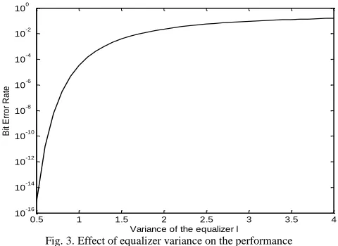
will improve. For a given input noise variance and channel characteristics, Fig. 3 shows the relationship between Γ and the BER. It is clear that the noise performance of the system deteriorates as Γ is increased.
Fig. 3. Effect of equalizer variance on the performance
Another important factor that affects the system noise
performance is the block length m. It can be seen from Eqns
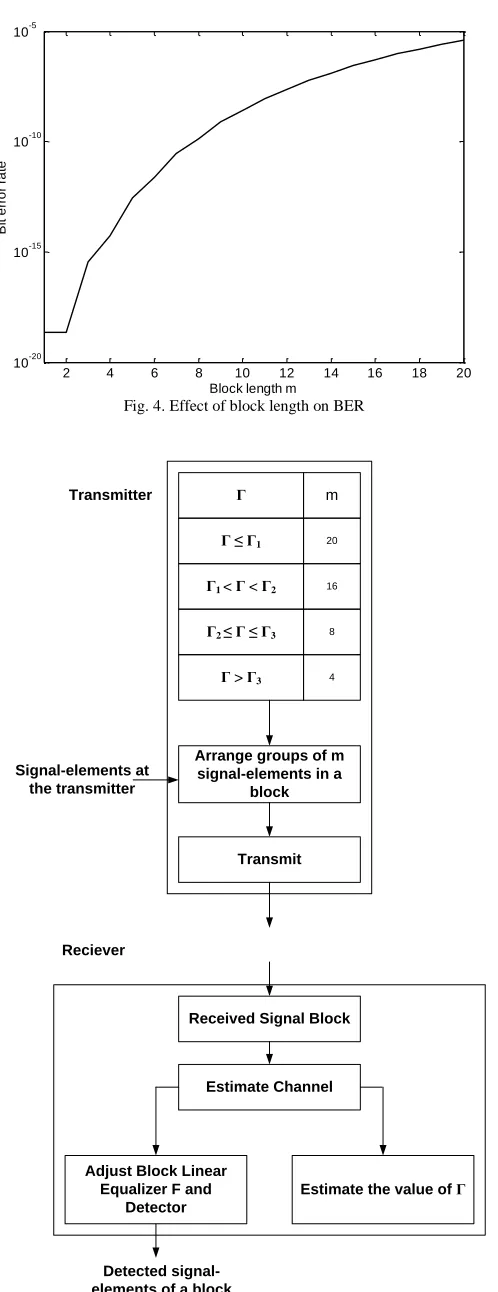
(9) & (11) that for a given channel distortion, as m increases the value of Γ will also increase. Moreover, the increase in the value of Γ will be higher in cases where the channel introduces higher inter-symbol interference (greater amplitude distortion).Fig. 4 shows the degradation in the noise performance of the system as the block length is increased. Thus in order to keep the BLE operating at an optimum block size, it is desirable to adaptively change the size of the signal block as and when the cannel distortion changes. Such an adaptive implementation will take the form of an adaptive
0.5 1 1.5 2 2.5 3 3.5 4
10-16 10-14 10-12 10-10 10-8 10-6 10-4 10-2 100
Variance of the equalizer l
B
it
E
rr
o
r
R
a
Fig. 4. Effect of block length on BER
Γ
Γ ≤ Γ1
Γ1 < Γ < Γ2
Γ2 ≤ Γ ≤ Γ3
Γ > Γ3
m
20
16
8
4
Arrange groups of m signal-elements in a
block
Transmit Signal-elements at
the transmitter Transmitter
Received Signal Block
Estimate Channel
Adjust Block Linear Equalizer F and
Detector
Estimate the value of Γ
Reciever
Detected signal-elements of a block
Fig. 5. Adaptive algorithm for block linear equalizer
algorithm that will use short signal blocks when the channel distortion is large (large values of Γ) and long signal blocks for low channel distortion (lower values of Γ). It is, therefore, required to calculate the value of Γ from the knowledge of the estimated channel impulse response and send this information back at the transmitter through the reverse channel. The signal block size will then be selected at the transmitter on the basis of a look up table. It may be pointed out that this process is to be repeated only when the channel is estimated and not before the transmission of each block of signal-elements. This algorithm is shown in Fig. 5. Only four distinct values of block size are considered for four distinct ranges of Γ. The resulting BLE is called the Adaptive Block Linear Equalizer (ABLE).
IV. RESULTS
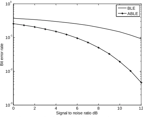
Fig. 6 shows the noise performance of the Adaptive Block Linear Equalizer (ABLE). For the sake of comparison the performance of Block Linear Equalizer (BLE) is also shown. The results have been obtained through computer simulation. In this simulation, a total of 10000 block of data were transmitted with four distinct ranges of Γ. It was assumed that the channel is estimated correctly using any of the techniques referred to in the paper. For the BLE, the block size m was taken to be 8 so that a total number of 80,0000 signal bits were transmitted in the simulation.
TABLE I.
Normalized Channel Impulse Response
The impulse responses of the channels considered in this simulation test are shown in Table 1. In each case the impulse response is normalized to have unit energy. These channel characteristics are selected as these are close to the realistic channels [3,7,8] and cover wide ranges of channel lengths and distortions. The algorithm takes the block length of size 20 if
the value of Γ is below 1.2, and the block length m = 16 if Γ
lies between 1.2 and 2. If Γ lies between 2 and 3, the block length used is 8, and the last choice of block length is 4, which is taken for higher values of Γ.
From Fig 6 it can be seen that ABLE gains consider advantage in tolerance to noise over the BLE. Moreover, by using the adaptive algorithm proposed in this paper , the systems managed to send 125000 bits in the same 10000 block with an average of 12.5 signal bits/block. This indicates that ABLE uses the channel bandwidth more efficiently as compared to BLE. The performance of ABLE can be
2 4 6 8 10 12 14 16 18 20
10-20 10-15 10-10 10-5
Block length m
B
it
e
rr
o
r
ra
te
Channel Sampled Impulse Response (1.000) -1/2 [1.000 0.000 0.000] (1.500) -1/2 [0.500 1.000 -0.500] (2.000)-1/2 [1.000 0.000 1.000] (6.000) -1/2 [0.707 2.234 0.707] (2.000) -1/2 [1.000 1.000 0.000] (6.000) -1/2 [1.000 2.000 1.000] (1.500) -1/2 [0.500 1.000 0.500]
improved further by incorporating more ranges for Γ. However, this will increase the complexity of the system. How many ranges should be used for Γ will depend on the environment and application.
Fig. 6. Comparison between the BER for BLE and ABLE.
V. CONCLUSIONS
In Block Data Transmission System the noise performance of the Block Linear Equalizer depends on the channel distortion and the size of the transmitted signal block. The algorithm presented in this paper adaptively controls the block size by estimating the channel distortion from the estimated impulse response of the channel. For higher values of channel distortion the block size is reduced and for smaller values of channel distortion the block size is increased. This is done at the transmitter through a look up table. The resulting block linear equalizer is called the Adaptive Block Linear Equalizer (ABLE). It achieves considerable advantage in tolerance to noise over the BLE and has a higher information transmission rate for the same element transmission rate. This advantage is achieved with only a slight increase in equipment complexity.
REFERENCES
[1] Lucky, R.W., Salz,J., and Waldon, E.J. Jr., “Principles of Data Communication”, McGraw Hill Book Company, New York, 1968. [2] Macchi, O., “Adaptive Processing: Least Mean Square Approach with
Application in Transmission”, John Wiley and Sons, New York, 1995. [3] J. Proakis, Digital Communications, 3rd ed. New York: McGraw Hill,
1995.
[4] J. M. Wozencraft and I.M. Jacobs, Principles of Communication Engineering, New York, Wiley 1965, pp 211 – 233.
[5] S. Crozier, D. Falconer, and S. Mahmoud, "Reduced Complexity Short- Block Data Detection Techniques for Fading Time-Dispersive Channels," IEEE Transactions on Vehicular Technology, vol. 41, no. 3, pp. 255-265, 1992.
[6] K. Hayashi and H. Sakai, "Single Carrier Block Transmission without Guard Interval," presented at the 17th Annual IEEE International Symposium on Personal, Indoor and Mobile Radio Communications, Finland, pp. 1-5, 2006.
[7] G. Kaleh, "Channel Equalization for Block Transmission Systems," IEEE Journal on Selected Areas in Communications, vol. 13, no. 1, pp. 110-121, 1995.
[8] F. Ghani, “Performance Bounds for Block Transmission System”
Proceedings of the 2004 IEEE Asia-Pacific Conference on Circuits and Systems held in December 6-9, 2004, Tainan, Taiwan
[9] D. Borah, "Estimation of Frequency-Selective CDMA Channels with Large Possible Delay and Doppler Spreads," IEEE Transactions on Vehicular Technology, vol. 55, no. 4, pp. 1126-1136, 2006.
[10] B. R. Vojcic and W. M. Jang, "Transmitter Precoding in Synchronous Multiuser Communications," IEEE Transaction on Communications, vol. 46, no. 10, 1998.
[11] F. Ghani and M. Kumaran, “Adaptive Linear Detector For Block Data Transmission System” Proceeding of the International Conference on Robotics, Vision, Information and Signal Processing ROVISP2005 held at Penang, Malaysia 20-22 July 2005, pp 939-943
[12] S. Crosier, D. Falconer, and S. Mahmoud, "Least Sum of Squared Error (LSSE) Channel Estimation, " Institute of Electrical Engineering Proceedings, vol. 138, pp. 371-378, 1991.
[13] R. Varga, Matrix Iterative Analysis. Englewood Cliffs , New Jersey: Prentice Hall, 1962.
Farid Ghani received B.Sc. (Engg) and M.Sc. (Engg) degrees from Aligarh Muslim University, India and M.Sc. and Ph.D. degrees from Loughborough University Of Technology (U.K).
From 1982 to 2007 and for varying durations, he worked as Professor of Communication Engineering at Aligarh Muslim University, India, Professor and Head of the Department of Electronics Engineering, Al-Fateh University, Libya, and Professor at Universiti Sains Malaysia. He is currently working as Professor in the School of Computer and Communication Engineering ,Universiti Malaysia Perlis, Malaysia. He is actively engaged in research in the general areas of digital and wireless communication, digital signal processing including image coding and adaptive systems. He has a large number of publications to his credit and is a reviewer for several international research journals.
Professor Ghani is Fellow of Institution of Engineering and Technology (IET) UK, Fellow of Institution of Electronics and Telecommunication Engineers(IETE) India, and Fellow of National Telematic Forum (NTF) India. He is also registered with the Council of Engineers(C.Eng) UK as Chartered Engineer.
Mutamed Khatib received B.Sc. in Telecommunication Engineering from Yarmouk University, Irbid, Jordan in 1996 and M.Sc. in Electrical & Electronic Engineering from Jordan University for Science & Technology, Irbid, Jordan in 2003. He received his Ph.D.Degree in wireless and mobile systems from University Sains Malaysia (USM), Malaysia in 2009.
From 1996 to 2005, he worked as Transmission, Outside Broadcasting & Studio Engineer in Palestinian Broadcasting Corporation (PBC).
From 2005 to 2009 he worked as an Instructor in the Department of Electrical Engineering ,Palestine Technical University (Khadoury) ,Tul Karm – Palestine. Since September 2009, Dr Mutamed Khateeb is working as Assistant professor in the same university. Dr. Khatib has a number of publications to his credit in various international journals and conference proceedings. He is a member of Palestinian Engineers Association.
0 2 4 6 8 10 12
10-3 10-2 10-1 100
Signal to noise ratio dB
B
it
e
rr
o
r
ra
te