Fixed Point and Floating Point High Speed Hardware
Multipliers- A comparison of Bit Serial and Wallace
Tree Multipliers Using
Booth Recoding
1
Awais Ahmed,
2Asim Shahzad
1,2 School of Electrical Engineering, University of Faisalabad, Pakistan.
Abstract-- Faster processing units requires speedy arithmetic block especially for higher frequency clocks of the system, the arithmetic block must fulfill the greater requirement of power. Area and speed are usually conflicting constraints. This paper presents the best solution to this problem by comparing the results of different multipliers. BOOTH recoding is implemented in this research and hence, provided a healthy comparison for Bit serial and Wallace tree multipliers of different size.
I. INTRODUCTION
The results for Bit serial multiplier are taken from my previous research paper which is mentioned in reference section. Multipliers are considered slowest parts of a system as well as they are the major components of high performance systems used extensively in digital electronics such as microprocessors, digital signal processors and FIR Filters etc. The performance of any system is determined by the performance of multipliers because they are the slowest part in the system. Moreover, they require greater area than other components. Therefore, optimizing the speed and area of the multipliers is the foremost issue. As area and speed are both conflicting constraints this means that for greater speed we need larger area [1]. As multipliers from one of the most important components of many systems, analyzing different multipliers will help us to frame a better system with area and better speed.
II. METHODOLOGY AND EXPERIMENTAL WORK
A number of algorithms are proposed and used to design multipliers and the actual implementation is mostly some little refinements and variations of the few basic algorithms presented here. In this research two typed of multiplier are implemented for fixed and floating point [1]. Different sized of two algorithms for high speed hardware multipliers were studied and implemented i.e. Bit serial multiplier, Wallace tree multiplier. The workings of these multipliers were compared by implementing each of them separately in VHDL. A number of high speed adder designs are developed and algorithm and design of these adders are discussed.
When two binary numbers, multiplicand “N” and multiplier “M” are multiplied the algorithm utilizes distributive property
of multiplication. The multiplication of M*N consists of partial products which represents a single component of the total product. A binary multiplier can be decomposed in to a sum of partial products. It can be done by selection of a partial product value, and some shifting that is independent of the selection value [1].
BINARY NUMBER REPRESENTATION
Fixed Point ArithmeticMostly fixed point multiplication is preferred because it’s easier algorithm. A multiplication can be implemented using a network of binary shifts and adders. The hardware cost can be approximated with the required numbers of adders and subtractors. The basic concept of multiplication is similar to the traditional pencil and paper method.
Floating Point ArithmeticThe non-integer numbers are represented in various forms. Whereas, one of those method is called floating point representation. The real number is represented in scientific notation where the binary word is divided into mantissa and exponent. This method has a fixed window of representation, which limits it from representing very large or very small numbers [5].
IEEE 754 has defined two types of storage layouts for floating points.
Single Precision 32 bits: 1 S-bit, 8 Exponent bits & 23 fraction bits. Double Precision 64 bits: 1 S-bit, 11 Exponent bits & 52 fraction bits.
A simple floating point multiplication for two binary numbers can be seen below mathematically.
(F1 2 E1) (F2 * 2 E2) (F1 F
2) 2 (E1 E2) F 2 E
[Equation-1]
Fig. 1. Flowchart for floating point multiplication [1]
Algorithms and Architectures
There are too many algorithms that can be used but two algorithms will be discussed and implemented in this article i.e., bit-serial multipliers and Wallace tree multipliers [4].
Bit-Sequential Multiplier
In Bit sequential multiplier also known as bit serial multiplier, input bits arrive on a single wire over a number of clock cycles and output bits are produces serially (Figure 1). Digital serial architecture process more than one bits at a time. This is done by dividing the N-bit word into X different digits
of Y bits wide each, where N is X*Y. The main objective behind this approach is to maximize the speed of operator by a factor greater than its size. It works in the similar manner of manual multiplication of two decimals. This is relatively slow because adding N partial product requires N clock cycles. The easiest clocking scheme is to make use of a system clock. If the multiplier is embedded in a larger system, the clock in normally much slower than the maximum speed at which the simple iterative multiplier can be clocked, so if the delay is to be minimized and expensive and tricky clock multiplier is needed or the hardware must be self-clocked [1-7].
Fig. 2. Simple bit-serial multiplier[1]
Fixed Point 16x16 Bit-serial Design
In order to design this multiplier, 33 bit accumulator is used to store the result.
”AND”, “OR”, “XOR” gates were used to implement bit adders [6]. A state machine was designed for multiplication to shift the bits. Total number of 32 states was used to perform the operation. When state is 0 and “st” is 1 the multiplier is loaded into accumulator and at the same time state changes to 1. The function named “add16” is used to computes two 16 bit vectors whose result is 17 bit. This represents the adder output which is loaded into “ACC” and at the same time the state counter is incremented. The right shift on the “ACC” is accomplished by loading “ACC” with 0 concatenated with upper 32 bits of accumulator. The states
Fig. 3. 16x16 Bit Serial Fixed point multiplier simulation
It is clear that at 800ns 16 bit multiplicand having value of 229 in decimal is multiplied with the multiplier of 63549 value in decimal and their product is 14552721 which is at 1350ns because all the states are finished and the done signal is up at this stage.
Floating Point 16x16 Bit-serial Design
The same multiplier is designed for greater number of bits by using greater accumulator size. Floating Point 16x16 Bit serial design 16 bits for multiplicand and multipliers were divided into 10 bit mantissas and 6 bits of exponents. The 10x10 bit
serial multiplication for mantissas of the 16x16 bit floating point multiplier. The 10x10bit multiplication is done in the similar manner as done above for the fixed point multiplier. The exponents are added to find the exponent of the product. Afterwards resulted exponents were normalized and adjusted the decimal point for the product. The final exponent and mantissa of the product is loaded properly according to floating point representation [1].
The simulation results of the floated point can be seen below in Figure 4.
Fig. 4. 16x16 Bit Serial Floating point multiplier simulation
Booth Recoding:
Booth recoding is used to reduce the number of Partial products for 2‟s complement numbers. It is possible to reduce the number of partial products by half, by using the technique of radix 4 Booth recoding. The basic idea is that, instead of shifting and adding for every column of the multiplier term and multiplying by 1 or 0, we only take every second column, and multiply by ±1, ±2, or 0, to obtain the same results [2]. Partial Product 0 = Multiplicand * -1, shifted left 0 bits (x -1) Partial Product 1 = Multiplicand * 2, shifted left 2 bits (x 8) This is the same result as the equivalent shift and add method:
Partial Product 0 = Multiplicand * 1, shifted left 0 bits (x 1) Partial Product 1 = Multiplicand * 1, shifted left 1 bits (x 2) Partial Product 2 = Multiplicand * 1, shifted left 2 bits (x 4)
Partial Product 3 = Multiplicand * 0, shifted left 3 bits (x 0)
Radix 4 Booth Recoding
To Booth recode the multiplier term, I considered the bits in blocks of three, such that each block overlaps the previous block by one bit. Grouping starts from the LSB, and the first block only uses two bits of the multiplier [2].
Fig. 6. Grouping of bits from the multiplier term, for use in Booth recoding
[1]
so that we know what happened in the last block, as the MSB of the block acts like a sign bit.
Wallace tree multipliers:
A Wallace tree is an implementation of an adder tree designed for minimum propagation delay. Rather than completely adding the partial products in pairs, the Wallace tree sums up all the bits of the same weights in a merged tree. Each layer of the tree therefore reduces the number of vectors by a factor of 3:2. The tree has as many layers as is necessary to reduce the number of vectors to two (a carry and a sum). A conventional adder is used to combine these to obtain the final product. In my design the partial products were generated using booth recoder and then they are added using Wallace tree adder similar to carry save adder approach. The last row of carry and sum output is added together with the carry skewed to the left by single position. [3]
Fixed Point 16x16 Wallace Tree multiplier design
For Wallace tree multiplier design, “x” is the 4 bit data input, “CI” is carry input and “S” is sum output. “C” is the carry output for the next row and “CO” is the carry output to the next unit adder directly to the left of the column. The idea is to get the “CO” to the left unit adder faster than the “S” and “C” output. Two more temporary results “temp1” and
“temp2” are calculated based on “x”. Output “S” is obtained with “temp1” and “CI” input and output “C” is generated. The module for Wallace tree multiplier is designed with the width of multiplier and multiplicand and a constant “WIDE” is declared to indicate the width of the product. “Constant Deep” is defined to indicate the number of unit adder rows and partial product “PP” is declared. Signals “COSIG”, “CSIG” and “SCIG” are declared to connect unit adder outputs “CO”, “C” and “S” respectively along with another signal RECODER_BITS, that is declared to be one more than the width of multiplier. Component unit adder and recoder are declared.
The right most column values for “COSIG”, “CSIG” and “SCIG” are initialized. Component recoder is initialized 8 times. Note that each group of 3 recoding bits overlap one bit with the last group of recoder bits. The output of the recoder bit shifted 2 bits each time. At the end, all unit adders are initialized.
The carry and sum outputs from the last row of the unit adders are added. Note that the carry bits are sifted one bit position to be added with the corresponding sum bit output. Finally the product output is formed.
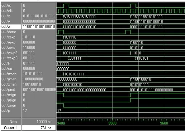
In the figure8 recode bits can be seen which are recoded using booth recoder. Different examples for multiplication can be seen in the figure8.
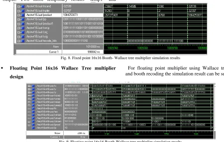
Fig. 8. Fixed point 16x16 Booth- Wallace tree multiplier simulation results
Floating Point 16x16 Wallace Tree multiplier
design
For floating point multiplier using Wallace tree technique and booth recoding the simulation result can be seen below;
Fig. 9. Floating point 16x16 Booth-Wallace tree multiplier simulation results
In the examples above we can see that in floating point (-2.5x10-73)10 = (0)10 or (40265318400)10 (40000000000)10 this is the price we have to pay if we want to be able to handle a large range of numbers with such a small number of bits.
III. IMPLEMENTATION RESULTS
Different algorithms discussed in this article where discussions and results for Bit serial multipliers and Parallel multipliers are grabbed from my previous research while Wallace tree multiplier is discussed completely. Implementation results contains Area and Delay comparisons for Bit serial, Parallel and Wallace tree multipliers ranging from 8 bits size of each to 128 bits size.
The table below gives the implementation results from synthesis of these multipliers using Xilinx ISE 13.1 tool. The best results based upon compiled values on maximum speed and minimum area is presented here.
It also represents the worst case propagation delay for each design in these tables.
Table I
Comparison results for fixed point multiplier
The table I gives the results of fixed point multipliers of different sizes form 8 bits to 128 bits simulated for two different types of multipliers.
Table II
Comparison result for floating point multiplier
Table II gives the synthesis results for the floating point multiplier for 16x16 bit vector. These results can be compared with the fixed point multipliers of same technique to observe the difference.
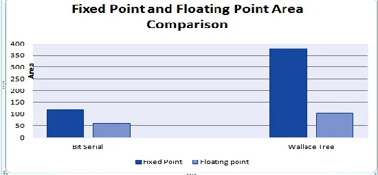
Fixed point and Floating point area comparison graph is shown below which shows clearly that the floating point design occupied less area than the fixed point multiplier. This result was anticipated earlier and the reason behind it is simple as in floating point multiplier only mantissa bits are multiplier while other bits for sign and exponent are added. Therefore, the number of slices occupied by the floating point is lower in number because few bits are multiplied using the multiplication techniques.
Fig. 12. Fixed point and floating point area comparison graph
The delay comparison can be seen below between fixed point and floating point multiplier and it can be seen clearly that fixed point multiplier has greater delay than floating point multiplier design whereas in bit serial the delay of both designs are very close to each other.
Fig. 13. Fixed point and floating point delay comparison graph
IV. CONCLUSION
Different multipliers are designed using VHDL and additionally, Booth algorithm is used to demonstrate the area comparison and delay comparison graphs in order to adopt the suitable multiplier according to the requirement. As multipliers are the slow part of the device in digital electronics, so they are needed to chose accurately. In accordance with Figure 12 and Figure 13, it can be seen clearly that the maximum area usage is for fixed point Wallace tree multiplier and the minimum area is recorded for fixed point Bit serial multipliers. In addition, the delay for Bit serial is recorded minimum and maximum delay is shown for Parallel multipliers both fixed point and floating point.
REFERENCES
[1] Awais Ahmed, Syed haider Abbas, Muhammad Faheem Siddique and Hussnain Haider ”Evaluation of high speed hardware multipliers- Fixed point and Floating point”. IJECE, Vol.3 No.6, December 2013, pp.805~814
[3] Wallace C.S „‟A suggestion for fast multiplier‟‟ IEEE Trans. Comput;. Pg 14-17. Feb 1964.
[4] Carl Burch, Hendrix College, September 2011, „‟Floating point representation IEEE-754‟‟ Garry W Bewick. “Fast multiplication: Algorithms and implementation”. Feb 1994. [5] Carl Burch, Hendrix College, September 2011, „‟Floating
point representation IEEE-754‟‟
[6] L.Kuhnel and Hartmut Schmeck, „‟A closer look at VLSI Multiplication‟‟ Integration- the VLSI Journal. Sept 1988 [7] S.G Smith, M.S McGregor and P.B Denyer, ‟‟techniques to
![Fig. 1. Flowchart for floating point multiplication [1] of Y bits wide each, where N is X*Y](https://thumb-us.123doks.com/thumbv2/123dok_us/1362113.1645479/2.612.171.448.410.545/fig-flowchart-floating-point-multiplication-y-bits-wide.webp)