Sharif University of Technology
Scientia IranicaTransactions B: Mechanical Engineering www.scientiairanica.com
Pre- and post-buckling analysis of functionally graded
beams subjected to statically mechanical and thermal
loads
M. Darvizeh
a;, A. Darvizeh
a, R. Ansari
band A. Alijani
aa. Department of Mechanical Engineering, Bandar Anzali Branch, Islamic Azad University, Bandar Anzali, Iran. b. Department of Mechanical Engineering, The University of Guilan, Rasht, P.O. Box 3756, Iran.
Received 1 December 2012; received in revised form 1 October 2013; accepted 18 November 2014
KEYWORDS Beam;
Functionally graded materials;
Post-buckling; Finite element analysis.
Abstract. In this paper, the pre- and post-buckling behavior of beams made of Functionally Graded Materials (FGMs), a mixture of ceramic and metal, under separate mechanical and thermal loading, is studied. To this end, the nite element formulation is established, based on the Euler-Bernoulli beam theory. The eects of geometrical nonlinearity and imperfection are taken into account. The arc-length algorithm is employed to obtain the secondary path beyond the bifurcation point. The inuences of material index, imperfection, geometrical parameters and dierent boundary conditions of simply-supported, clamped-simply and clamped-clamped, on the post-buckling characteristics of FGM beams, are thoroughly investigated. The results generated are compared with the existing data in the literature and good agreements are achieved. The investigation undertaken here proves the necessity of performing post-buckling analysis on FGM beams, especially with simply-supported end conditions.
© 2015 Sharif University of Technology. All rights reserved.
1. Introduction
Over the last three decades, the development of conventional materials towards composite materials and then Functionally Graded Materials (FGMs) has played an important role in the production of more ecient engineering equipment and structures. The mechanical behavior of FGM structures has been ex-tensively studied in the literature [1-28]. Murin et al. [1] carried out an exact solution of the bending vibration problem of FGM beams. Aminbaghai et al. [2] modeled a free vibration of two-dimensional FGM beams with continuous spatial variation of ma-terial properties. They homogenized the varying material properties and the calculated other related parameters using the multilayered beam and direct
*. Corresponding author.
E-mail address: [email protected] (M. Darvizeh)
integration methods. Kapuria et al. [3] presented a theoretical model for the bending and free vibra-tion response of layered FGM beams. Sankar [4] obtained an elasticity solution for a functionally graded beam subjected to transverse loads. A simple Euler-Bernoulli type beam theory was also developed on the basis of the assumption that plane sections re-mained plane and normal to the beam axis. Sankar further found that beam theory results agree quite well with the elasticity solution for beams with large length-to-thickness ratio under uniform loading with a longer sinusoidal wavelength. Sankarand Tzeng [5] solved thermoelastic equilibrium equations for a func-tionally graded beam in a closed form to obtain the axial stress distribution. The study of Lu et al. [6] concerned elasticity solutions of FGM beams by the dierential quadrature method. Chakraborty et al. [7] performed analysis on static, free vibration and wave propagation of functionally graded beams
by means of the FE method. Li [8] developed a unied approach to analyze static and dynamic be-haviors of the Timoshenko and Euler-Bernoulli FGM beams. Li et al. [9] further discussed the thermal post-buckling of FGM Timoshenko beams by the shooting method. They expressed the eects of material gra-dient properties on buckling deformation at critical temperatures. Kiani and Eslami [10] investigated the thermal buckling analysis of FGM beams, based on the Euler-Bernoulli method, and discussed how inuential geometry and materials are on the critical buckling temperature.
Shariat et al. [11-13] reviewed buckling phe-nomena in perfect and imperfect functionally graded plates subjected to both mechanical and thermal loads. Zhao et al. [14] described the mechanical and ther-mal buckling behavior of functionally graded plates with arbitrary geometry, including plates that contain square and circular holes at the centre. A nite strip method was applied to analyze the buckling behavior of rectangular Functionally Graded Plates (FGPs) under thermal load [15].
Most previous studies [1-15] have been centered on the linear buckling of FGM beams. The necessity of post-buckling analysis of such structures has not been clearly discussed in the literature. The primary aim of this paper is to highlight the signicance of performing post-buckling analysis of FGM beams under dierent mechanical and thermal loading conditions and to reveal the importance of boundary conditions. The present study aims to pursue an earlier developed pre-buckling analysis of FGM beams [10], by the authors, to assess the post-buckling stage, non-linearly, by means of the nite element method.
2. Finite element formulation
Figure 1 illustrates an FGM beam with length L, width b, and thickness h. The x axis is assumed to be along the beam axis, and the material gradient is considered to be along the z axis.
The balance of virtual work in static analysis between the vector of external force, P, and internal
Figure 1. Coordinate system, geometric characteristics and displacement details of beam.
stress, , gives: Z
d"Tdv dTP = 0; (1)
in which d" and are the variation of strain and displacement vector, respectively. The strain used in Eq. (1) is written in the presence of thermal strain, based on the Euler-Bernoulli kinematic equation by the following relation:
"x=@u@x +12
@w @x
2
z@@x2w2 0T; (2)
where, 0T is the change of temperature relative to
the reference temperature. By employing the nite element method, displacements of each element, ue, we,
are discretized using the linear interpolation and cubic Hermite functions, respectively, as [29-33]:
ue= 2
X
I=1
NIuI; N1=1 2 ; N2= 1 + 2 ; (3)
we= 2
X
I=1
HI()wI+ HI()l2ewI0
; (4)
H1= 14 2 3 + 3;
H2= 14 2 + 3 3;
H1= 14 1 2+ 3;
H2= 1 + 2+ 3:
Therefore, each element with length le consists of two
nodes, and the deformation of each node is represented by three components (u; w; w0)
I. The kinematic Eq. (2)
can be also divided into linear strain, "0, non-linear
strain, "NL, and thermal strain, "th, i.e.:
" = "0+ "NL+ "th; (5)
in which: "0=@u@x z@
2w
@x2 = (Bu zBb) = B0; (5a)
"th= 0T; (5b)
"NL= 12
@w @x
2
=12A: (5c)
Considering = G and BNL = AG, where is the
beam displacement vector, the kinematic equation is re-written as follows [34]:
The increment of the above equation yields:
d" = (B0+ BNL) d: (7)
For the elastic deformation, the constitutive equation is expressed by = E" in which E is the elasticity modulus.
Substituting Eqs. (6) and (7) into Eq. (1), the virtual work equation in the presence of mechanical and thermal loadings is written as:
dTK
0+12N1+13N2
dTZ (BT 0
+BT
NL)E0T dV dTP = 0; (8)
where: K0=
Z BT
0EB0dV; (8a)
N1=
Z BT
0EBNL+ BNLT EB0+ GTS0GdV; (8b)
N2=
Z BT
NLEBNL+ GTSNLGdV: (8c)
By neglecting the thermal load in Eq. (8), the equilib-rium equation reduces as:
Ks = P; Ks= K0+12N1+13N2; (9)
whose incremental equation takes the form:
KT = P; KT = K0+ N1+ N2; (10)
in which Ks and KT are the secant stiness matrix
and tangent stiness matrix, respectively. If the mechanical load in Eq. (8) vanishes, Eq. (11) presents an equilibrium equation for thermal loading as:
Ks = Fth; Fth=
Z BT
0 + BNLT
E0T dV: (11)
The increment of the above equation gives:
KT = Fth; KT = K0 Kth+ N1+ N2: (12)
Here: Fth=
Z BT
0 + BNLT
E(0T )dV; (12a)
Kth =
Z GTS
thGdV; (12b)
where Fth and Kth are the thermal force vector and
geometric stiness matrix due to thermal stress, re-spectively.
3. Post-buckling of perfect beams
The nonlinear response of the post-buckling stage and its stability condition are of prime interest to researchers. Determination of the buckling mode, the secondary state of the structure after deformation, the critical buckling load as the post-buckling initial point, and following the right path beyond the bifurcation point are among signicant achievements in buckling phenomena [35-43].
In order to analyze the instability problem, iden-tication of the singular buckling point and switching from the pre-buckling to the post-buckling path are of signicant importance. One method for indentifying the buckling point is the analysis of the sign change of diagonal elements in the tangent stiness matrix [35]:
KT = LTDL; (13)
where D is a diagonal matrix. The pre-buckling path is traced through the linear solution of the equilibrium problem. On this path, at each step, the criterion of reaching the buckling point is checked by determining the tangent stiness matrix at the converged geometrical situation. After reaching the buckling point, the primary path will be continued by following the analysis in the same way. Therefore, an algorithm is needed to be employed for switching to the secondary path. In this algorithm, the bifurcation point, as the last point of the pre-buckling path, is perturbed to the neighboring point. To analyze the non-linear geometric, along with the stability problem, the iterative incremental strategy of the cylindrical arc-length is employed [44-47]. This perturbation is applied through a scaled eigenvector to the converged deformation as [48]:
p= c+ jjjj ; (14)
where p, in Eq. (14), corresponds to the displacement
at the neighboring point, c is the converged
displace-ment at the bifurcation point, and is an eigenvector of the tangent stiness matrix. Term scales the distance between perturbation and bifurcation points.
After perturbation to p, the next step is to
determine a point on the secondary path resulting in equilibrium equations to converge. Then, the post-buckling path is traced as an iterative incremental algorithm, non-linearly.
In thermal loading, an eigenvalue analysis for calculating the critical buckling temperature would support the results of non-linear thermal buckling:
jK0 Kthj = 0: (15)
The process through which the secondary path is determined in thermal loading would be fairly dierent
from mechanical loading. Consider a beam with immovable supports under thermal loading. Before critical buckling temperature, if the temperature rises, no deformation will be observed at the nodes. In other words, under thermal loading, the pre-buckling path may not be observed, as seen in mechanical loading. Under such conditions, it is suggested that, in order to leave the primary path, perturbation to the neighboring points should be performed at the rst load step, and, afterwards, the equilibrium points on the secondary path could be identied using the iterative incremental arc-length algorithm.
4. Post-buckling of imperfect beams
The presence of initial deformation, known as imper-fection, in structures, and studying their eects on the mechanical behavior of the structures, are very important. The eect of ctitious initial displacement on kinematic equations and that of imperfection on the strength of structures have been investigated in [49-52]. Due to a number of reasons, including manu-facturing technique, plastic deformation, etc., it is possible to deform the beam with a displacement along its lateral axis to have an initially imperfect beam. The following two methods present the modeling of imperfect beams. In this way, there is no need to perturb the beam to the neighboring point to identify the post-buckling path.
4.1. Kinematic formulation
The strain-displacement relation for the Euler-Bernoulli imperfect beam in the absence of thermal loading would be written in the following form [49]:
"x=@u@x +12
@w @x
2
z@@x2w2 +@w@x0@w@x; (16a)
where w0is the initial transverse displacement eld due
to the beam imperfection. Using Eqs. (4a) and (4c), Eq. (16a) can be written as:
"x=
B0+@w@x0G
+1
2BNL: (16b)
4.2. Transverse force
It is possible to model the initial deformation using a transverse force that remains constant, while the axial load increases, as shown in Figure 2. To do so, it is desirable that the transverse force has no eect on the internal forces of the loaded beam. However, the displacements resulted from the transverse force can be used in the equations as imperfection.
The magnitude of imperfection and its shape can be controlled by changing the value of P0 and its
location, respectively.
Figure 2. Imperfection modeling by lateral force.
5. Functional graded beams
The used FGM material is comprised of ceramic and metal, whose properties are distributed from metal to ceramic smoothly by a power-law function. The volume fractions of metal and ceramic, which are represented by Vmand Vc, respectively, show the distribution of two
phases of material from fully metal to fully ceramic as a function of thickness direction, z:
Vm= 1 Vc; Vc=
1 2+
z h
k
; (17)
where k is the power-law material index [1]. If the FGM beam is axially loaded at the centroid, it creates a moment due to the non-homogeneity of the material along the thickness. In order to obtain a pure compressive axial load, the axial force must be located at the neutral center. Figure 3 depicts the neutral center position (h0) relative to the centroid. In other
words, the uniformly distributed axial force on the cross-section can be considered a resultant force, P , on the centroid. If the resultant force acts on the neutral center, this will result in a non-uniform distribution on the cross-section:
P h0= M; (18a)
where:
Figure 3. Centroid and neutral center positions of FGM beams.
P = Z
xdA; M =
Z
zxdA: (18b)
Substituting Eq. (18b) into Eq. (18a) gives the neutral center position:
h0=
^
B"x D^
^
A"x B^: (18c)
Here, "x is the strain term independent of z, and
is the curvature. Other parameters in Eq. (18c) are dened as:
= @@x2w2; A =^ Z h
2 h 2
D(z)dz; ^
B = Z h
2 h 2
zD(z)dz; D =^ Z h
2 h 2
z2D(z)dz: (18d)
In the Euler-Bernoulli formulation for an FGM beam, the nonlinear term of "x and the curvature can be
neglected in the pre-buckling state, as the beam axes do not deform. Therefore, before the buckling point, Eq. (18c) can be expressed as:
h0=
^ B ^
A: (18e)
In thermal loading analysis, temperature, T0, is
con-sidered the reference temperature, and the changes in temperature relative to the reference temperature are dened as 0T = T T0. Here, thermal loads for FGM
beams are considered to vary uniformly, linearly and non-linearly, according to Table 1. The temperatures in rich-ceramic and rich-metal sides are considered Tc
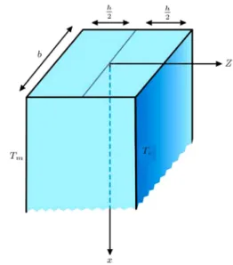
and Tm, respectively, as shown in Figure 4.
6. Results and discussion
Consider a metal-ceramic FGM beam consisting of Aluminum and Alumina whose mechanical properties are listed in Table 2 [10].
Figure 4. Temperature distribution of FGM beams from ceramic to metal in the thickness direction.
Figure 5. Types of boundary conditions for a) mechanical loading on movable beams, and b) thermal loading on immovable beams.
6.1. FGM beam under mechanical load
In mechanical loading, one side of the support is immovable, while the other side is movable. But, in thermal loading, both sides of the supports are considered immovable in the analyses, as shown in Figure 5. In mechanical loading, the geometrical
Table 1. Types of thermal loads.
Type of thermal loading T (Temperature) Uniform temperature rise T = Tc= Tm
Linear temperature
distribution T = Tm+ (Tc Tm) 12+hz
Nonlinear temperature distribution
T = Tm+(TcDTm)
P
5 i=0( 1)
i ik+1
Kc Km Km
i 1 2+zh
ik+1
D =P5 i=0( 1)
i ik+1
Kc Km Km
i
Table 2. Material properties of FGM beams. Materials
Properties Aluminum Alumina
Young's modulus (GPa) Em= 70 Ec= 380
Thermal expansion (/C)
m= 23 10 6 c= 7:4 10 6
Thermal conductivity (W/mK) K
parameters of the beam, including width, thickness and length, are considered b, h and L, respectively, in which, h = b = 0:01 m and L=h = 100.
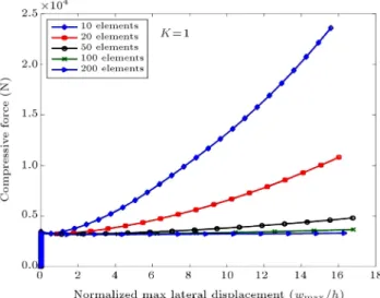
The convergence rate of the nite element method, when the number of elements increases, is illustrated in Figure 6. The boundary conditions of the beam are considered Clamped-Simply (C-S), and
Figure 6. Convergence study for an FGM beam with C-S supports, k = 1 and L=h = 100.
the power-law index is assumed to be k = 1. For the beam presented in the gure, 50 elements are enough for lateral deection of wmax=h < 16, while 20 elements
can give accurate results for wmax=h < 2.
Figures 7 and 8 show the pre- and post-buckling paths, critical buckling load, end shortening and second conguration of the ceramic-rich perfect beam with Clamped-Clamped (C-C) and Simply Supported (S-S) boundary conditions, respectively.
From Eq. (13), the post-buckling path is detected for the rst axial mode by changing the sign of an element in diagonal matrix D. Note that if it is desired to follow the post-buckling path for the Nth axial mode, it is necessary to change the sign of N elements of the diagonal matrix D. Then, perturbation to the neighboring point is performed in order to switch to the secondary path. To obtain the third axial mode, the signs of three elements of diagonal matrix D should change before perturbation. The critical buckling load obtained from the present work can be compared to the buckling equations for simply supported condition (Pcr = n2L22EI) and clamped boundary condition
(Pcr =n(0:5L)22EI2).
Figure 9 illustrates the post-buckling path for various indices of FGM material and dierent boundary
Figure 7. Buckling characteristics of isotropic beams with C-C supports, L=h = 100 and elasticity modulus of 270 GPa: a) Eect of buckling mode on the force-displacement curve; b) eect of buckling mode on the end shortening-displacement curve; c) lateral displacement of beam at mode 1; and d) lateral displacement of beam at mode 3.
Figure 8. Buckling characteristics of isotropic beams with S-S supports, L=h = 100, and elasticity modulus of 270 GPa: a) Eect of buckling mode on the force-displacement curve; b) eect of buckling mode on the end shortening-displacement curve; c) lateral displacement of beam at mode 1; and d) lateral displacement of beam at mode 3.
Figure 9. Post-buckling behavior of FGM beams with dierent boundary conditions, various indices and L=h = 100 subjected to mechanical loading: a) C-C supports; b) C-S supports; and c) S-S supports.
Figure 10. Imperfection eect on post-buckling behavior of FGM beams with C-C B.Cs, L=h = 100 and two dierent material indices: a) Eect of imperfection factor on the force-displacement curve at k = 0:2; b) eect of imperfection factor on the force-displacement curve at k = 2; c) eect of imperfection factor on the end shortening-displacement curve at k = 0:2; and d) eect of imperfection factor on the end shortening-Displacement curve at k = 2.
conditions. According to this gure, the buckling point and the secondary path of the FGM beam for all bound-ary conditions and all material indices are between those of ceramic-rich and metal-rich. The highest strength against the buckling phenomenon corresponds to the ceramic-rich for C-C boundary conditions.
Figure 10 depicts the behavior of perfect and imperfect FGM beams for two material indices, k = 0:2 and k = 2. By increasing the initial transverse displacement, w0 in Eq. (16), or the lateral force,
P0, the initial conguration of an imperfect beam is
more deviated from that of a perfect beam, and the eect of imperfection diminishes at higher values of wmax=h.
Both methods of imposing imperfection, i.e. Kinematic Formulation and Transverse Force, agree well with each other. In the rst method, the initial transverse displacement eld is inserted in kinematic Eq. (16), as the rst axial mode, and, in the second method, the lateral force, P0, is applied in the middle
of the beam. These methods are almost equivalent because of the linear relationship of P0= K0w0.
Figure 11 demonstrates a comparison between positions of compressive axial force applied at the centroid and the neutral center. As seen, the force po-sition does not aect the results for clamped-clamped
boundary conditions. In homogeneous materials, like fully ceramic, the positions of the centroid and the neutral center are the same, as the results show. How-ever, in C-S and S-S boundary conditions, according to the gure, for inhomogeneous materials, the force position will yield dierent results at the centroid and the neutral center. The reason is that when the material is not homogenous and the axial load is applied at the centroid, a relatively small bending moment is combined with the axial compressive force. This bending moment deviates the beam state from its initial situation. Therefore, there is no need for perturbation to the neighboring point in obtaining the post-buckling path. The post-buckling curves, when the axial load is applied to the centroid and neutral axis, are converged at large values of wmax=h. Note
that if the axial load is applied at the neutral center, the post-buckling path will be traced via perturbing the buckling point.
6.2. FGM beam under thermal load
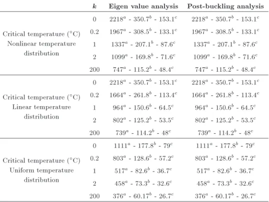
In the case of non-uniform thermal distribution, the dierence between the metal-rich FGM temperature and the reference temperature is 5 degrees centigrade. Table 3 presents a comparison between critical buckling temperatures obtained using two dierent methods,
Figure 11. Eect of location of the applied compressive force on FGM beams with dierent boundary conditions, various material indices and L=h = 100: a) S-S supports; b) C-S supports; and c) C-C supports.
including eigenvalue (linear) analysis and non-linear analysis for three types of thermal load. This table has been drawn for a beam with clamped-clamped boundary conditions and for three L=h ratios (a; b; c), which are 20, 50 and 75, respectively.
Figure 12 presents a comparison between the
Figure 12. Eects of material index on the critical buckling temperature for a C-S FGM beam.
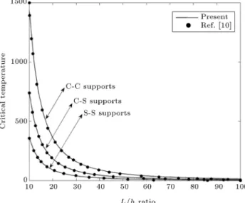
Figure 13. Inuence of geometrical parameters on the critical buckling temperature for a fully metallic beam under uniformly thermal loading.
results of the present work and those of Ref. [10]. The eect of ceramic and metal distribution of the FGM material index (k) on buckling temperature has been illustrated for a uniform temperature rise and boundary conditions of C-S.
Figure 13 also illustrates the eect of L=h ratio on the critical buckling temperature of fully metallic beams with dierent boundary conditions for a uniform temperature increase.
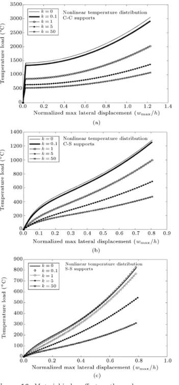
Figures 14-16 show the post-buckling paths for uniform, linear, and non-linear distributions, respec-tively, for FGM beams with various material indices and boundary conditions at L=H = 25. For all material indexes in C-C boundary conditions, a pertur-bation to the neighboring point should be performed at the rst load step as the arc-length algorithm
Table 3. Comparison of eigenvalue and nonlinear analyses for the critical buckling temperature of the beam with C-C boundary conditions.
k Eigen value analysis Post-buckling analysis
Critical temperature (C)
Nonlinear temperature distribution
0 2218a- 350.7b- 153.1c 2218a - 350.7b- 153.1c
0.2 1967a- 308.5b- 133.1c 1967a - 308.5b- 133.1c
1 1337a - 207.1b - 87.6c 1337a- 207.1b- 87.6c
2 1099a - 169.8b - 71.6c 1099a- 169.8b- 71.6c
200 747a- 115.2b- 48.4c 747a - 115.2b- 48.4c
Critical temperature (C)
Linear temperature distribution
0 2218a- 350.7b- 153.1c 2218a - 350.7b- 153.1c
0.2 1664a- 261.8b- 113.4c 1664a - 261.8b- 113.4c
1 964a- 150.6b- 64.5c 964a - 150.6b- 64.5c
2 802a- 125.2b- 53.5c 802a - 125.2b- 53.5c
200 739a - 114.2b - 48c 739a- 114.2b- 48c
Critical temperature (C)
Uniform temperature distribution
0 1111a- 177.8b- 79c 1111a - 177.8b - 79c
0.2 803a- 128.6b- 57.2c 803a - 128.6b- 57.2c
1 517a - 82.6b - 36.7c 517a- 82.6b- 36.7c
2 458a - 73.3b - 32.6c 458a- 73.3b- 32.6c
200 376a- 60.17b- 26.7c 376a - 60.17b- 26.7c which can identify the secondary path; for example in
uniform temperature distribution (Figure 14(a)) and k = 0. There is no deformation at nodes up to 711C before the secondary path. In this case, the
post-buckling path is followed without following the pre-buckling path. Such perturbation is no longer needed for C-S and S-S boundary conditions, except for fully ceramic. The reason is that, for C-S and S-S supports at k 6= 0, a bending moment due to a dierence in the thermal expansion coecient of two phases combined with the thermal axial load, makes a deviation from the initial situation and the secondary path follows. In other words, when the compound beam consisting of two materials is ex-posed to thermal loading, a moment is produced at two ends due to the dierence in thermal expansion coecients. This moment intends to bend the beam. In this situation, the buckling problem is converted to a nonlinear bending problem, except for clamped-clamped boundary conditions where the created mo-ment is inactive. The dierence of thermal expansion coecients in metal-ceramic material and the behavior of these two phases under thermal load, conceptually, illustrates the impression of a temperature distribution type on the nonlinear buckling or bending behavior of the beam.
Unlike Figure 14, in Figures 15 and 16, the temperatures are distributed linearly and nonlinearly from ceramic towards metal, respectively. In both non-uniform distributions, the dierence between the
metal-rich temperature and the reference temperature has been considered 5C. However, in uniform
dis-tribution, the temperature simultaneously increases in both sides of metal-rich and ceramic-rich. So, by considering the thermal expansion coecient dif-ference between metal and ceramic, and the higher sensitivity of metal to temperature, uniform temper-ature distribution generates more deviation than the other two non-uniform temperature distributions for C-S and S-S boundary conditions. In other words, uniform temperature distribution causes more ther-mal strain on the metal side than the other two distributions, as these strains make more coupling axial-bending load. Also, in Figures 15 and 16, in which the thermal distribution is non-uniform, it can be seen that even for fully ceramic, which has constant thermal properties, a bending moment is produced due to the dierence in temperature on two sides, which deviates the beam from the initial situa-tion. This shows an appropriate conformity between the physical behavior and buckling analysis of the beam.
7. Conclusion
The present article describes the pre- and post-buckling behavior of beams made of Functionally Graded Ma-terials (FGMs) under separate mechanical and ther-mal loading. Based on the Euler beam theory, a geometrically non-linear analysis in conjunction with
Figure 14. Material index eect on thermal
post-buckling under uniform temperature loading: a) C-C supports; b) C-S supports; and c) S-S supports.
a stability analysis was employed, using the nite element method. The eects of the beam geometry and material properties of FGM on the critical buckling load, post-buckling path and current conguration after deformation are fully investigated. An algorithm of arc-length for tracing pre-buckling and post-buckling paths was utilized.
Performing a post-buckling analysis of FGM beams is quite essential, especially for
simply-support-Figure 15. Material index eect on thermal
post-buckling for linear temperature distribution: a) C-C supports; b) C-S supports; and c) S-S supports.
ted end conditions, due to the moments induced at supports by the material inhomogeneity.
In determination of the thermal post-buckling of FGM beams, unlike uniform temperature rise, linear temperature distribution can be an appropriate esti-mation for nonlinear temperature distribution.
The post-buckling curve of an FGM beam that is sensitive to the material index lies between that of the pure ceramic and pure metal.
Figure 16. Material index eect on thermal
post-buckling for nonlinear temperature distribution: a) C-C supports; b) C-S supports; and c) S-S supports.
highest load carrying capacity when an FGM beam is exposed to mechanical or thermal loading.
Acknowledgments
The authors would like to acknowledge the members of the Institute of Continuum Mechanics at Leibniz University, Hannover, especially Professor Peter Wrig-gers and Dr. Laura de Lorenzis, for their constant scientic support. Also, the authors are grateful to the
University of Guilan, Iran, where this research work was completed.
Nomenclature
b Width
D Eigenvalues of tangent stiness matrix
E Elasticity modulus
Fth Thermal force vector
h Thickness
h0 Neutral center position
H Hermitian shape function
k Power law index
Kth Geometric stiness matrix due to
thermal stress
KS Secant stiness matrix
KT Tangent stiness matrix
le Length of element
L Length of beam
N Lagrangian shape function P Mechanical force vector T0 Reference temperature
u Axial displacement of middle surface
V Volume
Vm Metal volume fraction
Vc Ceramic volume fraction
w Transverse deection of middle surface w0 Initial transverse deection
Stress
" Strain "0 Linear strain
"NL Nonlinear strain
"th Thermal strain
Thermal expansion coecient
Curvature
Eigenvector of tangent stiness matrix 0T Change of temperature
Displacement vector
p Displacement of perturbed point
c Converged displacement at bifurcation
point
Shape function parameter
Perturbation parameter
References
1. Murin, J., Aminbaghai, M. and Kutis, V. \Exact solu-tion of the bending vibrasolu-tion problem of FGM beams with variation of material properties", Engineering Structures, 32, pp. 1631-1640 (2010).
2. Aminbaghai, A., Murin, J. and Kutis, V. \Modal analysis of the FGM-beams with continuous transver-sal symmetric and longitudinal variation of material properties with eect of large axial force", Engineering Structures, 34, pp. 314-329 (2012).
3. Kapuria, S., Bhattacharyya, M. and Kumar, A.N. \Bending and free vibration response of layered func-tionally graded beams: A theoretical model and its experimental validation", Composite Structures, 82, pp. 390-402 (2008).
4. Sankar, B.V. \An elasticity solution for functionally graded beams", Composites Science and Technology, 61, pp. 689-696 (2001).
5. Sankar, B.V. and Tzeng, J.T. \Thermal stresses in functionally graded beams", AIAA Journal, 40, pp. 1228-32 (2002).
6. Lu, C.F., Chen, W.Q., Xu, R.Q. and Lim, C.W. \Semi-analytical elasticity solutions for bi-directional functionally graded beams", International Journal of Solids and Structures, 45, pp. 258-275 (2008). 7. Chakraborty, A., Gopalakrishnan, S. and Reddy, J.N.
\A new beam nite element for the analysis of func-tionally graded materials", International Journal of Mechanical Sciences, 45, pp. 519-539 (2003).
8. Li, X.F. \A unied approach for analyzing static and dynamic behaviors of functionally graded Timoshenko and Euler-Bernoulli beams", Journal of Sound and Vibration, 318, pp. 1210-1222 (2008).
9. Li, S.R., Zhang, J.H. and Zhao, Y.G. \Thermal post-buckling of functionally graded material Timoshenko beams", Applied Mathematics and Mechanics, 27(6), pp. 803-810 (2006).
10. Kiani, Y. and Eslami, M.R. \Thermal buckling anal-ysis of functionally graded material beams", Int J. Mech. Mater., 6, pp. 229-238 (2010).
11. Samsam Shariat, B.A. and Eslami, M.R. \Thermal buckling of imperfect functionally graded plates", In-ternational Journal of Solids and Structures, 43, pp. 4082-4096 (2006).
12. Samsam Shariat, B.A. and Eslami, M.R. \Buckling of thick functionally graded plates under mechanical and thermal loads", Composite Structures, 78, pp. 433-439 (2007).
13. Samsam Shariat, B.A., Javaheri, R. and Eslami, M.R. \Buckling of imperfect functionally graded plates un-der in-plane compressive loading", Thin-Walled Struc-tures, 43, pp. 1020-1036 (2005).
14. Zhao, X., Lee, Y.Y. and Liew, K.M. \Mechanical and thermal buckling analysis of functionally graded plates", Composite Structures, 90, pp. 161-171 (2009). 15. Ghannadpour, S.A.M., Ovesy, H.R. and Nassirnia, M. \Buckling analysis of functionally graded plates under thermal loadings using the nite strip method", Computers and Structures, 108-109, pp. 93-99 (2012). 16. Natarajan, S. and Manickam, G. \Bending and vibra-tion of funcvibra-tionally graded material sandwich plates
using an accurate theory", Finite Elements in Analysis and Design, 57, pp. 32-42 (2012).
17. Nguyen, D.K. \Large displacement behavior of tapered cantilever Euler-Bernoull beams made of functionally graded material", Applied Mathematics and Computa-tion, 237, pp. 340-355 (2014).
18. Nguyen, T.K., Sab, K. and Bonnet, G. \First-order shear deformation plate models for functionally graded materials", Composite Structures, 83, pp. 25-36 (2008).
19. Vo, T.P., Thai, H.T., Nguyen, T.K., Maheri, A. and Lee, J. \Finite element model for vibration and buckling of functionally graded sandwich beams based on a rened shear deformation theory", Engineering Structures, 64, pp. 12-22 (2014).
20. Jodaei, A., Jalal, M. and Yas, M.H. \Free vibration analysis of functionally graded annular plates by state-space based dierential quadrature method and com-parative modeling by ANN", Composites, Part B, 43, pp. 340-353 (2012).
21. Mozafari, H. and Ayob, A. \Eect of thickness vari-ation on the mechanical buckling load in plates made of functionally graded materials", Procedia Technology, 1, pp. 496-504 (2012).
22. Nguyen, T.K., Vo, T.P. and Thai, H.T. \Static and vibration of axially loaded functionally graded beams based on the rst-order shear deformation theory", Composites Part B: Engineering, 55, pp. 147-157 (2013).
23. Alibeigloo, A. \Thermoelasticity analysis of function-ally graded beam with integrated surface piezoelec-tric layers", Composite Structures, 92, pp. 1535-1543 (2010).
24. Yaghoobi, H. and Torabi, M. \Post-buckling and non-linear free vibration analysis of geometrically imperfect functionally graded beams resting on nonlinear elastic foundation", Applied Mathematical Modeling, 37, pp. 8324-8340 (2013).
25. Wei, D., Liu, Y. and Xiang, Z. \An analytical method for free vibration analysis of functionally graded beams with edge cracks", Journal of Sound and Vibration, 331, pp. 1686-1700 (2012).
26. Lee, H. and Jang, Y.H. \Eect of the volume of a func-tionally graded material layer on fricfunc-tionally excited thermoelastic instability", Tribology International, 49, pp. 103-109 (2012).
27. Shen, H.S., Functionally Graded Materials Nonlinear Analysis Plates and Shells, CRC Press, Boca Raton (2009).
28. Li, S.R. and Batra, R.C. \Relations between loads of functionally graded Timoshenko and homogeneous Euler-Bernoulli beams", Composite Structures, 95, pp. 5-9 (2013).
29. Wriggers, P., Nonlinear Finite Element Methods, Springer-Verlag, Berlin Heidelberg (2008).
30. Zienkiewicz, O.C. and Taylor, R.L. \The nite element method", Solid Mechanics, 5th Ed., 2, Butterworth-Heinemann, Oxford (2000).
31. Criseld, M.A., Non-Linear Finite Element Analysis of Solids and Structures, Volume 2: Advanced Topics, John Wiley & Sons, Chichester (1997).
32. Bathe, K.J., Finite Element Procedures, Prentice-Hall, New Jersey (1996).
33. Reddy, J.N., An Introduction to Nonlinear Finite Element Analysis, Oxford University Press, New York (2004).
34. Wood, R.D. and Schreer, B. \Geometrically non-linear analysis a correlation of nite element nota-tions", International Journal for Numerical Methods in Engineering, 12, pp. 635-642 (1978).
35. Wagner, W. and Wriggers, P. \A simple method for the calculation of postcritical branches", Eng. Comput., 5, pp. 103-9 (1988).
36. Fang, W. and Wickert, J.A. \Post buckling of micro-machined beams", J. Micromechanics and Microengi-neering, 4, pp. 116-122 (1994).
37. Jabareen, M. \Rigorous buckling of laminated cylin-drical shells", Thin-Walled Structures, 47, pp. 233-240 (2009).
38. Patel, B.P., Singh, S. and Nath, Y. \Postbuckling char-acteristics of angle-ply laminated truncated circular conical shells", Communications in Nonlinear Science and Numerical Simulation, 13, pp. 1411-1430 (2008). 39. Zhu, D.S. and Cheung, Y.K. \Postbuckling analysis
of shells by spline nite strip method", Computers & Structures, 31(3), pp. 357-364 (1989).
40. Brush, D.O. and Almorth, B.O., Buckling of Bars, Plates, and Shells, McGraw-Hill, New York (1975). 41. Sheinman, I., Shaw, D. and Simitses, G.J. \Nonlinear
analysis of axially-loaded laminated cylindrical shells", Computers & Structures, 16, pp. 131-137 (1983). 42. Sheinman, I. and Jabareen, M. \Postbuckling of
lami-nated cylindrical shells in dierent formulation", AIAA Journal, 43(5), pp. 1117-1123 (2005).
43. Flores, F.G. and Godoy, L.A. \Elastic postbuckling analysis via nite element and perturbation tech-niques. Part II: Application to shells of revolution", Numerical Methods in Engineering, 36, pp. 331-354 (1993).
44. Criseld, M.A. \A fast incremental/iterative solution procedure that handles \Snap-Through", Computers & Structures, 13, pp. 55-62 (1981).
45. Criseld, M.A. \An arc-length method including line searches and accelerations", Numerical Methods in Engineering, 19, pp. 1269-1289 (1983).
46. Feng, Y.T., Peric, D. and Owen, D.R.J. \Determina-tion of travel direc\Determina-tions in path-following methods", Mathl. and Comput. Modelling, 21, pp. 43-59 (1995).
47. De Souza Neto, E.A., Peric, D. and Owen, D.R.J., Computational Methods for Plasticity Theory and Ap-plications, John Wiley & Sons, Chichester (2008). 48. Papadrakskis, M. \Solving large-scale nonlinear
prob-lems in solid and structural mechanics", In Solving Large-Scale Problems in Mechanics, John Wiley & Sons, Chichester, pp. 183-223 (1993).
49. Debongnie, J.F. \Physical interpretation and general-ization of Marguerre's shallow shell theory", Int. J. Engineering. Sci., 17, pp. 387-399 (1979).
50. Hong, T. and Teng, J.G. \Imperfection sensitivity and postbuckling analysis of elastic shells of revolution", Thin-Walled Structures, 46, pp. 1338-1350 (2008). 51. Distefano, J.N. and Sackman, J.L. \On the stability
of an initially imperfect, nonlinearly viscoelastic col-umn", Int. J. Solids Structures, 4, pp. 341-354 (1968). 52. Combescure, A. \Static and dynamic buckling of large thin shells", Nuclear Engineering and Design, 92, pp. 339-354 (1986).
Biographies
Mansour Darvizeh received MS and PhD degrees from the University of Manchester, UK, and is cur-rently Professor of Mechanical Engineering at the University of Guilan, Iran. His research activities in-clude mathematical modeling of engineering structures made of metal composites, brous composites, and functionally graded materials and smart materials. Abolfazl Darvizeh received his MS and PhD de-grees from the University of Manchester, UK, and is currently Professor of Mechanical Engineering at the University of Guilan, Iran. His primary research interests and publications involve impact mechanics and the dynamic behavior of materials. He has received awards from the Ministry of Science, Research and Technology, and ISME, Iran, for his contributions to impact engineering and has had over one hundred scientic research papers published.
Reza Ansari received his MS and PhD (2008) degrees from the University of Guilan, Iran, where he is currently Associate Professor of Mechanical Engineer-ing. His areas of research include computational me-chanics, numerical analysis, nano-, micro- and macro-mechanics.
Ali Alijani received his MS and PhD (2013) degrees from the University of Guilan, Iran, and is currently Assistant Professor in Mechanical Engineering at the Islamic Azad University, Bandar Anzali, Iran. His research activities are in the elds of buckling analysis and crack propagation.