B
P/N 51333:B ECN 03-419 Document 51333
10/03/2003 Rev:
Fire Alarm Control Panel
NFS-640
Programming Manual
While a fire alarm system may lower insurance rates, it is not a substitute for fire insurance!
An automatic fire alarm system—typically made up of smoke detectors, heat detectors, manual pull stations, audible warning devices, and a fire alarm control panel with remote notification capability—can provide early warning of a develop-ing fire. Such a system, however, does not assure protection against property damage or loss of life resulting from a fire. The Manufacturer recommends that smoke and/or heat detec-tors be located throughout a protected premise following the recommendations of the current edition of the National Fire Protection Association Standard 72-1999 (NFPA 72-1999), manufacturer's recommendations, State and local codes, and the recommendations contained in the Guide for Proper Use of System Smoke Detectors, which is made available at no charge to all installing dealers. A study by the Federal Emer-gency Management AEmer-gency (an aEmer-gency of the United States government) indicated that smoke detectors may not go off in as many as 35% of all fires. While fire alarm systems are designed to provide early warning against fire, they do not guarantee warning or protection against fire. A fire alarm sys-tem may not provide timely or adequate warning, or simply may not function, for a variety of reasons:
Smoke detectors may not sense fire where smoke cannot reach the detectors such as in chimneys, in or behind walls, on roofs, or on the other side of closed doors. Smoke detectors also may not sense a fire on another level or floor of a building. A second-floor detector, for example, may not sense a first-floor or basement fire.
Particles of combustion or “smoke” from a developing fire may not reach the sensing chambers of smoke detectors because:
• Barriers such as closed or partially closed doors, walls, or chimneys may inhibit particle or smoke flow.
• Smoke particles may become “cold,” stratify, and not reach the ceiling or upper walls where detectors are located. • Smoke particles may be blown away from detectors by air
outlets.
• Smoke particles may be drawn into air returns before reaching the detector.
The amount of “smoke” present may be insufficient to alarm smoke detectors. Smoke detectors are designed to alarm at various levels of smoke density. If such density levels are not created by a developing fire at the location of detectors, the detectors will not go into alarm.
Smoke detectors, even when working properly, have sensing limitations. Detectors that have photoelectronic sensing chambers tend to detect smoldering fires better than flaming fires, which have little visible smoke. Detectors that have ion-izing-type sensing chambers tend to detect fast-flaming fires better than smoldering fires. Because fires develop in different ways and are often unpredictable in their growth, neither type of detector is necessarily best and a given type of detector may not provide adequate warning of a fire.
Smoke detectors cannot be expected to provide adequate warning of fires caused by arson, children playing with matches (especially in bedrooms), smoking in bed, and violent
Heat detectors do not sense particles of combustion and alarm only when heat on their sensors increases at a predeter-mined rate or reaches a predeterpredeter-mined level. Rate-of-rise heat detectors may be subject to reduced sensitivity over time. For this reason, the rate-of-rise feature of each detector should be tested at least once per year by a qualified fire pro-tection specialist. Heat detectors are designed to protect property, not life.
IMPORTANT! Smoke detectors must be installed in the same room as the control panel and in rooms used by the sys-tem for the connection of alarm transmission wiring, communi-cations, signaling, and/or power. If detectors are not so located, a developing fire may damage the alarm system, crip-pling its ability to report a fire.
Audible warning devices such as bells may not alert people if these devices are located on the other side of closed or partly open doors or are located on another floor of a building. Any warning device may fail to alert people with a disability or those who have recently consumed drugs, alcohol or medica-tion. Please note that:
• Strobes can, under certain circumstances, cause seizures in people with conditions such as epilepsy.
• Studies have shown that certain people, even when they hear a fire alarm signal, do not respond or comprehend the meaning of the signal. It is the property owner's responsi-bility to conduct fire drills and other training exercise to make people aware of fire alarm signals and instruct them on the proper reaction to alarm signals.
• In rare instances, the sounding of a warning device can cause temporary or permanent hearing loss.
A fire alarm system will not operate without any electrical power. If AC power fails, the system will operate from standby batteries only for a specified time and only if the batteries have been properly maintained and replaced regularly.
Equipment used in the system may not be technically com-patible with the control panel. It is essential to use only equip-ment listed for service with your control panel.
Telephone lines needed to transmit alarm signals from a premise to a central monitoring station may be out of service or temporarily disabled. For added protection against tele-phone line failure, backup radio transmission systems are rec-ommended.
The most common cause of fire alarm malfunction is inade-quate maintenance. To keep the entire fire alarm system in excellent working order, ongoing maintenance is required per the manufacturer's recommendations, and UL and NFPA stan-dards. At a minimum, the requirements of Chapter 7 of NFPA 72-1999 shall be followed. Environments with large amounts of dust, dirt or high air velocity require more frequent mainte-nance. A maintenance agreement should be arranged through the local manufacturer's representative. Maintenance should be scheduled monthly or as required by National and/ or local fire codes and should be performed by authorized pro-fessional fire alarm installers only. Adequate written records of all inspections should be kept.
Adherence to the following will aid in problem-free installation with long-term reliability:
WARNING - Several different sources of power can be connected to the fire alarm control panel. Disconnect all sources of power before servicing. The control unit and asso-ciated equipment may be damaged by removing and/or insert-ing cards, modules, or interconnectinsert-ing cables while the unit is energized. Do not attempt to install, service, or operate this unit until this manual is read and understood.
CAUTION - System Reacceptance Test after Software Changes. To ensure proper system operation, this product must be tested in accordance with NFPA 72-1999 Chapter 7 after any programming operation or change in site-specific software. Reacceptance testing is required after any change, addition or deletion of system components, or after any modifi-cation, repair or adjustment to system hardware or wiring. All components, circuits, system operations, or software func-tions known to be affected by a change must be 100% tested. In addition, to ensure that other operations are not inadvert-ently affected, at least 10% of initiating devices that are not directly affected by the change, up to a maximum of 50 devices, must also be tested and proper system operation ver-ified.
This system meets NFPA requirements for operation at 0°C to 49°C (32°F to 120°F) and at a relative humidity (noncon-densing) of 85% at 30°C (86°F) per NFPA, and 93% ± 2% at 32°C ± 2°C (89.6°F ± 1.1°F) per ULC. However, the useful life of the system's standby batteries and the electronic compo-nents may be adversely affected by extreme temperature ranges and humidity. Therefore, it is recommended that this system and all peripherals be installed in an environment with a nominal room temperature of 15-27° C/60-80° F.
Verify that wire sizes are adequate for all initiating and indi-cating device loops. Most devices cannot tolerate more than a 10% I.R. drop from the specified device voltage.
Like all solid state electronic devices, this system may operate erratically or can be damaged when subjected to light-ning-induced transients. Although no system is completely immune from lightning transients and interferences, proper grounding will reduce susceptibility. Overhead or outside aerial wiring is not recommended, due to an increased sus-ceptibility to nearby lightning strikes. Consult with the Techni-cal Services Department if any problems are anticipated or encountered.
Disconnect AC power and batteries prior to removing or inserting circuit boards. Failure to do so can damage circuits.
Remove all electronic assemblies prior to any drilling, filing, reaming, or punching of the enclosure. When possible, make all cable entries from the sides or rear. Before making modifi-cations, verify that they will not interfere with battery, trans-former, and printed circuit board location.
Do not tighten screw terminals more than 9 in-lbs. Over-tightening may damage threads, resulting in reduced ter-minal contact pressure and difficulty with screw terter-minal removal.
Though designed to last many years, system components can fail at any time. This system contains static-sensitive components. Always ground yourself with a proper wrist strap before handling any circuits so that static charges are removed from the body. Use static-suppressive packaging to protect electronic assemblies removed from the unit.
Follow the instructions in the installation, operating, and pro-gramming manuals. These instructions must be followed to avoid damage to the control panel and associated equipment. FACP operation and reliability depend upon proper installation by authorized personnel.
Precau-L-10-2003.fm
FCC Warning
WARNING: This equipment generates, uses, and can radiate radio frequency energy and if not installed and used in accordance with the instruction manual, may cause interference to radio communications. It has been tested and found to comply with the limits for class A computing device pursuant to Subpart B of Part 15 of FCC Rules, which is designed to provide reasonable protection against such interference when operated in a commercial environment. Operation of this equipment in a residential area is likely to cause interference, in which case the user will be required to correct the interference at his own expense.
Canadian Requirements
This digital apparatus does not exceed the Class A limits for radiation noise emissions from digital apparatus set out in the Radio Interference Regulations of the Cana-dian Department of Communications.
Le present appareil numerique n'emet pas de bruits radi-oelectriques depassant les limites applicables aux appa-reils numeriques de la classe A prescrites dans le Reglement sur le brouillage radioelectrique edicte par le ministere des Communications du Canada.
Acclimate Plus™, AWACS™, HARSH™, NOTI•FIRE•NET™, ONYX™, and VeriFire™ are trademarks, and FlashScan®, UniNet®, and VIEW®are registered trademarks of NOTIFIER. NION™ is a trademark of NIS. NIS™ and Notifier Integrated Systems™ are trademarks and NOTIFIER® is a registered trademark of Fire•Lite Alarms, Inc. Echelon® is a registered trademark and LonWorks™ is a trademark of Echelon Corporation. ARCNET® is a registered trademark of Datapoint Corporation. Microsoft® and Windows® are registered trademarks of the Microsoft Corporation. LEXAN® is a registered trademark of GE Plastics, a subsidiary of General Electric Company.
Your feedback helps us keep our documentation up-to-date and accurate. If you have any
com-ments or suggestions about our online Help or printed manuals, you can email us.
Please include the following information:
•
Product name and version number (if applicable)
•
Printed manual or online Help
•
Topic Title (for online Help)
•
Page number (for printed manual)
•
Brief description of content you think should be improved or corrected
•
Your suggestion for how to correct/improve documentation
Send email messages to:
Please note this email address is for documentation feedback only. If you have any technical
issues, please contact Technical Services.
About This Manual
Cautions and Warnings... 9
Typographic Conventions... 9
Supplemental Information... 10
Shortcuts to Operating Functions... 11
1. Getting Started
Introduction to the Control Panel... 12Features ... 12
Selecting a Programming Method... 13
How to Enter a Password... 13
2. Program Change
What is Program Change?... 14In This Section... 14
How to Enter Program Change... 15
How to Use the Basic Program... 15
How to Clear Memory (0=CLR) ... 16
How to Autoprogram the Control Panel (1=AUTO) ... 16
Purpose ... 16
Create a New Program for the Control Panel ... 17
How to Add a Device to the Program... 18
How to Remove a Device from the Program ... 18
How to Change Autoprogram Default Values ... 20
How to Modify or Delete a Point (2=POINT) ... 21
How to Modify an Addressable Detector Point... 22
How to Modify an Addressable Monitor Module Point... 23
Monitor Module Default Zone Assignments... 23
How to Modify an Addressable Control Module Point... 24
How to Modify NAC and Panel Circuit Points ... 25
How to Change a Password (3=PASSWD) ... 26
How to Create a System Message (4=MESSAGE)... 27
How to Create a Custom Zone Label (5=ZONE) ... 28
How to Program Special Zones (6=SPL FUNCT) ... 29
What are Special Zones? ... 29
How to Select Special Zones ... 30
How to Change Global System Functions (7=SYSTEM) ... 32
Global System Functions... 32
Annunciator Options... 33
ACS Selection Group Example ... 33
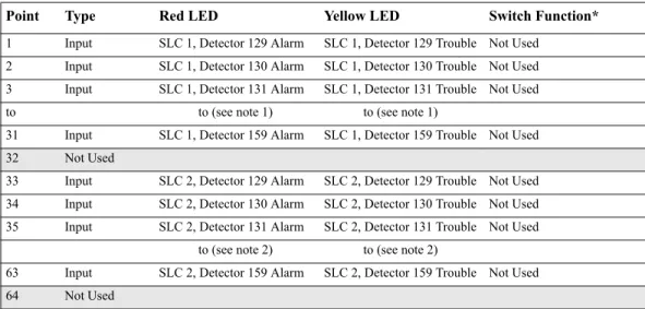
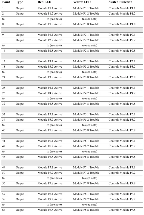
Annunciation Points ... 34
ACS Selection Group A: ... 35
ACS Selection Group B: ... 35
ACS Selection Group C (SLC #1, Modules 1-64): ... 36
ACS Selection Group D (SLC #2, Modules 1-64): ... 36
ACS Selection Group E (SLC #1, Modules 65-128): ... 36
ACS Selection Group F (SLC #2, Modules 65-128): ... 36
ACS Selection Group G (SLC #1 and #2, Modules 129-159): ... 37
ACS Selection Group H (SLC #1): ... 37
ACS Selection Group I (SLC #2): ... 37
ACS Selection Group J (SLC #1): ... 38
ACS Selection Group K (SLC #2): ... 38
ACS Selection Group N... 40
ACS Selection Group O... 40
How to Check the Program for Errors (8=CHECKPRG) ... 41
How to Use the Network Program... 42
How to Select the Network Program Options... 42
How to Use the Utility Program... 43
Utility Program Options... 43
How to Select Utility Program Options ... 43
How to Use FlashScan Poll... 44
Baud Rate of Serial Ports ... 45
3. Status Change
What is Status Change?... 46How to Enter Status Change... 46
Status Change Options ... 46
How to Disable or Enable a Point... 47
How to Change Sensitivity for a Detector... 48
How to Select a Detector... 48
How to Use the Detector Sensitivity Screen ... 48
How to Clear Alarm Verification Counters... 49
How to Clear the History Buffer... 49
How to Set the System Time and Date... 49
How to Do a Walk Test... 50
Basic Walk Test ... 50
Advanced Walk Test ... 51
Walk Test Activation Indications... 51
Viewing Walk Test Results... 52
Appendix A: Releasing Applications
What are Releasing Zones?... 53NFPA Releasing Applications... 53
How to Program a Releasing Zone... 54
How to Program a Delay Timer ... 54
How to Program an Abort Switch... 54
Definition of Abort Switches... 54
How an Abort Switch Works... 55
Programming a ULI Abort Switch... 56
Programming an IRI Abort Switch... 57
Programming an NYC Abort Switch... 59
Programming an AHJ Abort Switch... 61
Using Cross Zones ... 62
Purpose of Cross Zones ... 62
How Cross Zones Work... 62
How to Program a Soak Timer (NFPA 16 Applications Only) ... 64
Using Type Codes for Releasing Zones... 65
How to Program an Abort Switch... 66
How to Program a Manual Release Switch ... 67
How to Program a Manual Release Delay Switch... 68
How to Program a Second Shot Switch... 70
How to Program a Release End Bell Circuit ... 71
How to Program a ULC Release Circuit ... 72
How to Program a Release Circuit for an Output Circuit... 73
How to Program a Release Form-C Circuit... 74
How to Program a Release Code Bell Circuit ... 77
Initiating Devices... 78
Warning Sounders... 78
Auxiliary Control Functions... 78
ACS Annunciation... 78
Appendix B: Special Zone Outputs
Presignal and Positive Alarm Sequence (PAS)... 80What is Presignal and PAS? ... 80
Purpose ... 80
Notes on using F0 ... 80
Restrictions on using F0 ... 80
Selecting Presignal and PAS Outputs ... 81
Presignal ... 81
Positive Alarm Sequence (PAS)... 81
Time Control Zones... 82
Coding Functions for NACS and Panel Circuits... 82
Appendix C: AWACS™ Applications
AWACS Overview... 84AWACS Features... 84
Drift Compensation and Smoothing ... 84
Maintenance Warnings – Three Levels ... 85
Self-Optimizing Pre-Alarm... 86
Detector Sensitivity... 86
Cooperative Multi-Detector Sensing ... 87
Pre-Alarm... 88
Definition ... 88
Alert Level ... 88
Alert Functions ... 88
Example of an Alert Level... 88
Action Level... 88
Action Functions... 88
How to Select a Pre-Alarm Level ... 89
Detector Sensitivity Settings... 90
How to Select Pre-Alarm and Alarm Sensitivity... 90
How to Test Detectors Set Below 0.50% Obscuration per Foot... 91
Detector Maintenance Features... 92
Overview... 92
How to Access Detector Maintenance Information... 92
View Detector Maintenance for a Detector ... 92
Print a Detector Maintenance Report... 93
How to Interpret a Detector Status Display or Maintenance Report ... 93
Appendix D: CBE (Control-By-Event)
Description... 95Input and Outputs... 95
Equations... 95
Equation Entry... 96
Logic Functions ... 96
The “AND” Operator... 96
The “OR” Operator... 96
The “NOT” Operator ... 96
The “ONLY1” Operator ... 96
The “XZONE” Operator... 96
The “RANGE” Operator... 96
Equation Syntax Example ... 97
Evaluating an Equation ... 97
Argument Entries ... 98
Time Delay Functions ... 98
The “DEL” Operator... 98
The “SDEL” Operator ... 98
CBE Example... 99
Appendix E: Detector Initialization
Overview... 101System Testing and Detector Initialization... 101
How to Replace a Detector... 101
How to Manually Initialize a Detector... 102
Appendix F: Type Codes
What are Type Codes?... 103How to Select a Type Code... 103
In this Appendix... 103
Type Codes for Input Devices... 104
Overview ... 104
Type Codes for Intelligent Detectors ... 104
Type Codes for Monitor Modules... 105
Type Codes for Output Devices... 106
Overview ... 106
Type Codes for Control Modules... 106
NAC and Panel Circuit Type Codes ... 107
Cautions and Warnings
The following graphics appear in the manual to indicate a caution or a warning.
CAUTION: Information about procedures that could cause programming errors, runtime errors, or equipment damage.
WARNING: Information about procedures that could cause irreversible damage to the control panel, irreversible loss of programming data or personal injury.
Typographic Conventions
This manual uses the following conventions as listed below:
Table 1 Typographic Conventions in this Manual
!
When you see Specifies Example
text in small caps the text as it appears in the LCD display or on the control panel
MARCHTIME is a selection that appears in the LCD display; or Press the ENTER key text in quotes a reference to a section or a
LCD menu screen
“Status Change” specifies the Status Change section or menu screen bold text In body text, a number or
character that you enter
Press 1; means to press the number “1” on the keypad
italic text a specific document NFS-640 Installation Manual a graphic of the key In a graphic, a key as it
Supplemental Information
The table below provides a list of documents referenced in this manual, as well as documents for selected other compatible devices. The document series chart (DOC-NOT) provides the current document revision. A copy of this document is included in every shipment.
Compatible Conventional Devices (Non-addressable) Document Number
Device Compatibility Document 15378
Fire Alarm Control Panel (FACP) and Main Power Supply Installation Document Number
NFS-640 Installation, Operations, and Programming Manuals 51332, 51334, 51333
Voice Alarm System Manual 51252
SLC Wiring Manual 51253
Note: For individual SLC Devices, refer to the SLC Wiring Manual
Off-line Programming Utility Document Number
VeriFire™ Tools CD help file Veri•Fire Medium Systems Help File
VERIFIRE-TCD VERIFIRE-CD
Cabinets & Chassis Document Number
CAB-3/CAB-4 Series Cabinet Installation Document 15330
Battery/Peripherals Enclosure Installation Document 50295
Power Supplies, Auxiliary Power Supplies & Battery Chargers Document Number
ACPS-2406 Installation Manual 51304
APS-6R Instruction Manual 50702
CHG-120 Battery Charger Manual 50641
FCPS-24 Field Charger/Power Supply Manual 50059
Networking Document Number
Noti•Fire•Net Manual, Network Version 4.0 & Higher 51584
NCM-W/F Installation Document 51533
NCS Network Control Station Manual, Network Version 4.0 & Higher 51658
System Components Document Number
Annunciator Control System Manual 15842
Annunciator Fixed Module Manual 15048
AFM-16A Annunciator Fixed Module Manual 15207
ACM-8R Annunciator Control Module Manual 15342
LCD-80 Manual 15037
LCD-80TM Manual 51082
LDM Series Lamp Driver Annunciator Manual 15885
NCA Network Control Annunciator Manual 51482
SCS Smoke Control Manual (Smoke and HVAC Control Station) 15712
RPT-485W/RPT-485WF EIA-485 Annunciator Loop Repeater Manual 15640
DPI-232 Direct Panel Interface Manual 51499
TM-4 Installation Document (Reverse Polarity Transmitter) 51490
UDACT Manual (Universal Digital Alarm Communicator/Transmitter) 50050
ACT-2 Installation Document 51118
Table 2 Supplemental Documentation
Shortcuts to Operating Functions
To the left of each program function, you’ll find a keypad shortcut, which contains a series of keypad entries required to access the program function. All shortcuts start with the control panel in normal operation.
For example, the keypad shortcut to the left shows how to enter the Read Status function with the control panel in normal operation.
RA400Z Remote LED Annunciator Installation Document I56-508
RFX Wireless Interface Manual 51012
UZC-256 Universal Zone Coder Manual 15216
UZC-256 Programming Manual 15976
XP Transponder Manual 15888
XP10-M Installation Document I56-1803
XP5 Series Manual 50786
XP6-C Installation Document I56-1805
XP6-MA Installation Document I56-1806
XP6-R Installation Document I56-1804
Introduction to the Control Panel
The NFS-640 is an intelligent, field-programmable Fire Alarm Control Panel. Field-programming the control panel lets you customize the fire alarm system by selecting and setting program options for intelligent/addressable detectors and modules, Panel Circuits, and Notification Appliance Circuits (NACs).
This manual provides information for programming using the NFS-640 keypad connected to the control panel. VeriFire™ Tools must be used for programming if no keypad is used, or if an NCA (Network Control Annunciator) is used as the keypad in either a network or standalone application. Refer to VeriFire™ Tools for information on programming without the NFS-640 keypad, and the NFS-640 Installation Manual and NCA Manual for installation information.
For details on control panel operation, refer to the NFS-640 Operations Manual.
Features
Programming features include the following:
• Ease-of-use – Field program the control panel without needing special software skills. • Autoprogram option – Automatically detects newly installed, addressable devices, allowing
quicker installation.
• Local programming – program directly from the control panel keypad to reduce installation time.
• PC programming – input long data entry programming information on a PC; transfer programming data between a PC and the control panel using VeriFire™ Tools programming utility.
• Security – use passwords to control access to the control panel and protect memory.
• 80-Character (2x40) Liquid Crystal Display – view programming and device information on the control panel.
Selecting a Programming Method
The NFS-640 provides two methods for field-programming the control panel: • Using the built-in “Program Change” interface
• The VeriFire™ Tools Programming Utility The benefits of each method are listed below:
How to Enter a Password
The control panel provides two types of selectable passwords: • Program Change
• Status Change
Listed below are uses and the factory-setting for each password type:
Table 3 Programming Passwords
From the “SYSTEM NORMAL” screen: Press ENTER, press 1 (the password screen will display). Enter a password, then press ENTER:
Figure 1 Password Screen
In Program Change or Status Change, the control panel does the following: • Activates the System Trouble relay
• Shuts off the panel sounder
• Flashes the SYSTEMTROUBLE LED, which continues to flash while programming
For security purposes, you can change your passwords. To do so, follow the instructions in “How to Change a Password (3=passwd)” on page 26.
Note: The Read Status selection, which does not require a program password, is covered in the NFS-640 Operations
Manual.
Note: The NFS-640 continues to monitor and report alarms in programming mode, except in autoprogramming.
Programming method Benefits Refer to
Program Change Speed and convenience of putting the control panel on line quickly (using the Autoprogram function) and changing programming information.
Section “2. Program Change” on page 14
VeriFire™ Tools Programming Utility
Efficient means of creating and editing programs that require a lot of data entry.
Product documentation & Software help file
Password type Use to Factory Setting
Program Change (high level)
Enter Program Change option to program essential control panel functions, including basic system functions and utility options.
00000
Status Change (low level)
Enter Status Change option to program minor functions.
11111
Enter password here (00000 or 11111)
ENTER PROG OR STAT PASSWORD, THEN ENTER. (ESCAPE TO ABORT) _
What is Program Change?
Program Change is the programming level that lets you change the essential control panel functions, such as point programming, changing passwords, changing system functions. Included are four selections: Basic Program, Network, FlashScan Poll, and Utility Program.
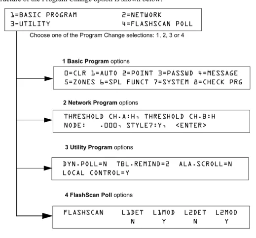
The structure of the Program Change option is shown below:
Figure 2 Program Change Selections
In This Section
This section contains instructions and sample screens for using the Program Change selections: • Basic Program The Basic Program lets you program essential functions, such as clearing the
program, Autoprogramming the system, programming points, and setting system functions. Refer to “How to Use the Basic Program” on page 15.
• Network Program The Network Program allows programming of network channel
thresholds, network node number, and wiring style.“How to Use the Network Program” on page 42.
• Utility Program The Utility Program screen provides selections for Dynamic Polling of the SLC(s), selecting a Trouble Reminder per NFPA, and enabling or disabling local control of the ACKNOWLEDGE/SCROLLDISPLAY, SIGNALSILENCE, and SYSTEMRESET keys. Refer to “How to Use the Utility Program” on page 43.
• FlashScan Poll The FlashScan Poll screen provides the option for selecting between CLIP (Classic Loop Interface Poll) and FlashScan Poll. Refer to “How to Use FlashScan Poll” on page 44.
Choose one of the Program Change selections: 1, 2, 3 or 4
1 Basic Program options
3 Utility Program options
4 FlashScan Poll options
2 Network Program options
1=BASIC PROGRAM 2=NETWORK
3-UTILITY 4=FLASHSCAN POLL
0=CLR 1=AUTO 2=POINT 3=PASSWD 4=MESSAGE 5=ZONES 6=SPL FUNCT 7=SYSTEM 8=CHECK PRG
THRESHOLD CH.A:H, THRESHOLD CH.B:H NODE: .000, STYLE7:Y, <ENTER>
DYN.POLL=N TBL.REMIND=2 ALA.SCROLL=N LOCAL CONTROL=Y
FLASHSCAN L1DET L1MOD L2DET L2MOD
How to Enter Program Change
To enter Program Change, follow these steps:
1. At the “SYSTEM NORMAL” screen, press the ENTER key. The control panel displays the “Entry” screen, as shown below:
2. At the “Entry” screen, press the 1 key. The control panel displays the “Enter Password” screen as shown below:
3. Enter your Program Change password (See “How to Enter a Password” on page 13). The control panel displays the “Program Change Selection” screen, as shown below:
4. Select a Program Change selection: 1, 2, 3 or 4.
How to Use the Basic Program
From the “Program Change Selection” screen, press the 1 key to display the “Basic Program” screen
which provides nine (9) options as shown below:
Press the number of any one of the nine (9) options as detailed below
Option 0=CLR - Clears all existing user programming. For details, refer to How to Clear Memory (0=CLR) on page 16. Note: The user is prompted to double-check that this is what is really wanted. Option 1=AUTO - Add or remove addressable devices to the control panel program. For details, refer to How to Autoprogram the Control Panel (1=AUTO) on page 16.
Option 2=POINT - Modify or delete a point. For details, refer to “How to Modify or Delete a Point (2=POINT)” on page 21.
Option 3=PASSWD - Change the Program Change or the Alter Status password. For details, refer to “How to Change a Password (3=PASSWORD)” on page 26.
Option 4=MESSAGE - Edit the 40-character message that displays on the first line. For details, refer to “How to Create a System Message (4=MESSAGE)” on page 27.
Option 5=ZONES - Edit the 19-character custom zone label for zones 01-99. For details, refer to “How to Create a Custom Zone Label (5=ZONE)” on page 28.
Option 6=SPL FUNCT - Program Releasing Zones and Special Zones. For details, refer to “How to Program Special Zones (6=SPL FUNCT)” on page 29.
Option 7=SYSTEM - Program Global System Functions. For details, refer to “How to Change Global System Functions (7=SYSTEM)” on page 32.
Option 8=CHECK PRG - Check the program for errors. For details, refer to “How to Check the Program for Errors (8=CHECK PRG)” on page 41.
1=PROGRAMMING 2=READ STATUS ENTRY
(ESCAPE TO ABORT)
ENTER PROG OR STAT PASSWORD, THEN ENTER.
(ESCAPE TO ABORT) _
1=BASIC PROGRAM 2=NETWORK
3-UTILITY 4=FLASHSCAN POLL
0=CLR 1=AUTO 2=POINT 3=PASSWD 4=MESSAGE 5=ZONES 6=SPL FUNCT 7=SYSTEM 8=CHECK PRG
How to Clear Memory (0=
CLR)
The Clear option removes all programming information from control panel memory. If installing the control panel for the first time, use option 0 to clear control panel memory. To do so, follow these steps:
1. From the “Basic Program” screen, press the 0 (zero) key to display the Clear Program screen. The
control panel prompts for verification as shown below:
2. Press the ENTER key to clear control panel memory or press the ESC key to exit the screen without clearing.
How to Autoprogram the Control Panel (1=
AUTO)
PurposeThe Autoprogram option identifies all addressable devices connected to the control panel. Devices include addressable detectors and modules connected to SLC 1 or SLC 2, Panel Circuits connected to J5 and J6, and NACs. You can use the Autoprogram option to create a new program and add or remove devices. A summary of the Autoprogram functions, when to use the functions, and where to find information on using the functions is found below:
Autoprogram Function Control Panel Configuration Refer to... Create a new program for
the control panel
A new control panel or a control panel with no existing program in memory.
“Create a New Program for the Control Panel” on page 17 Add one or more
SLC-connected detectors and modules to an existing program
A program exists in memory and you want to add a detector or module to the existing program—without modifying information for existing detectors and modules.
“How to Add a Device to the Program” on page 18
Remove one or more SLC-connected detectors and modules from an existing program
A program exists in memory and you want to remove an installed detector or module from the existing program—without modifying information for existing detectors and modules.
“How to Remove a Device from the Program” on page 18
View system defaults A program exists in memory and you want to view system settings assigned during Autoprogram, such as custom labels, passwords, and so on.
“How to Change Autoprogram Default Values” on page 20 Program Change
Password
PRESS ENTER TO CLEAR ENTIRE PROGRAM
Create a New Program for the Control Panel
This section covers how to use the Autoprogram option to create a new program for the control panel. The control panel will identify all addressable detectors and modules connected to the SLC.
To create a new program for the control panel, follow these steps:
1. Use the Clear option to clear program information from memory. For instructions on clearing memory, refer to “How to Clear Memory (0=CLR)” on page 16.
2. From the “Basic Program” screen, press the 1 key to start Autoprogram. While the control panel scans the system to identify all SLC devices, Panel Circuits and NACs, it displays the following screen:
When the autoprogram is finished identifying SLC devices, Panel Circuits and NACs, it displays a summary screen that gives a count of all the devices it has located. Refer to the following screen for an example of this display.
3. Press ENTER. All devices are automatically accepted during initial autoprogramming. The following screen displays briefly, followed by the SYSTEM NORMAL screen.
To edit the autoprogramming default values for a point, refer to”How to Modify or Delete a Point (2=POINT)” on page 21.
To edit the autoprogram default values assigned to all modules and detectors during autoprogramming, refer to “How to Change Autoprogram Default Values” on page 20.
Program Change Password
AUTOPROGRAM PLEASE WAIT
L1:010Dets, 159Mods L2:159Dets, 159Mods Panel Outputs: 64 Bells: 04
How to Add a Device to the Program
You can also use the Autoprogram option to add addressable devices to the control panel program.
Note: When using the Autoprogram option with an existing program, the control panel does not change program
information for installed and programmed devices.
The following steps describe how to add a new detector at SLC address 1D147 with 10 detectors in the existing program:
1. Physically install the addressable detector to SLC 1 at address 147 (for instructions, refer to the
NFS-640 Installation Manual and the installation document that comes with the detector).
2. From the “Basic Program” screen, press the 1 key to start Autoprogram. The Autoprogram Prompt screen appears in the LCD display as the control panel identifies addressable devices. When finished identifying addressable devices, the control panel displays information for the new detector at SLC address 1D147 on the LCD display as shown below:
3. Press the ENTER key to add detector 147 to the program with the default program information. If you want to change the default information, use the programming keys to do so, then press the ENTER key to add detector 147 to the program.
The Autoprogram Summary screen appears. You can verify addition of the detector to the program by noting the new count of detectors as shown below:
4. Press the ENTER key, then press the ESC key to save the program in memory and return to the “Basic Program” screen).
How to Remove a Device from the Program
You can also use the Autoprogram option to remove addressable detectors and modules from the control panel program.
Note: When using the Autoprogram option with an existing program, the control panel does not change program
information for installed and programmed devices.
The following steps describe how to delete a detector at SLC address 1D133 with 11 detectors connected to SLC 1 in the existing program:
1. Disconnect and remove the detector from SLC 1 at address 1D133.
2. From the “Basic Program” screen, press the 1 key to start Autoprogram. The Autoprogram Prompt screen displays while the control panel identifies addressable devices.
3. When finished identifying addressable devices, the control panel displays a screen, indicating a missing detector at SLC address 1D133 as shown below:
4. Press the ENTER key to delete detector 1D133 from the program.
The Autoprogram Summary screen appears. You can verify removal of the detector from the
PROGRM SMOKE(PHOTO) DETECTOR ADDR 1D147 03 __ __ __ __A8P8** 1D147
Note that the number of detectors increases (in this example from 10 to 11) to show the addition of the detector to SLC 1.
L1:011Dets, 159Mods L2:159Dets, 159Mods
Panel Outputs: 64 Bells: 04
Type Code
SLC loop number D (detector) or M (module) Three-digit address (001-159)
PROGRM SMOKE (ION) DETECTOR ADDR 1D133 DEVICE NOT ANSWERING DELETE FR MEM?1D133
program by noting the new count of detectors as shown below:
5. Press the ENTER key, then press the ESC key to save the program in memory and return to the “Basic Program” screen.
Note that the number of detectors decreases (from 11 to 10) to show the removal of the detector from SLC 1.
L1:010Dets, 159Mods L2:159Dets, 159Mods
How to Change Autoprogram Default Values
To assign system default values from the basic program screen, Press 0 (clear), then press 1
(autoprogram). Refer to the chart below for default values and how to modify them.
Function Default Values To Alter, refer to
Software Zones 01-99
default custom label “Zone xx” where xx is the number of the zone
Note: Zone 00 is reserved for a general alarm.
“How to Create a Custom Zone Label (5=ZONE)” on
page 28 F0 PRG PRESIGNAL FUNCT PRESIGNAL DELAY
DELAY=180 PAS=NO F00
“F0 (Presignal/PAS)” on page 30
Releasing Zones R0-R9
PRG RELEASE FUNCT RELEASE CONTROL DELAY=00 ABORT=ULI CROSS=N SOK=0000
“R0-R9 (Releasing Functions)” on page 30 and “How to Program a Releasing Zone” on page 54 F5 and F6 PRG TIME FUNCTION TIME CONTROL
ON=**:** OFF=**:** DAYS=********
“F5-F6 (Time Control Functions)” on page 30 F7 PRG HOLIDAY FUNCTION **/** **/** **/**
**/** **/** **/** **/** **/** **/**
“F7 (Holiday)” on page 31 F8 PRG CODING FUNCTION CODE TYPE
MARCH TIME F08
“F8 (Coding Function)” on page 31
F9 PRE-ALARM FUNCT ALERT
F09
“F9 (Pre-Alarm)” on page 31 System
Parameters
SIL INH=0000 AUTO=0077 0 VERIFY=30 USA TIME
TERM=N AC_DLY=Y LocT BLINK=01 ST=4 ACS=N
“How to Change Global System Functions (7=SYSTEM)” on page 32
Passwords Default programming passwords are: Program Change=00000
Status Change=11111
“How to Change a Password (3=PASSWD)” on page 26
SYSTEM NORMAL message
(YOUR CUSTOM SYSTEM MESSAGE HERE) SYSTEM NORMAL 10:23A 071201 Thu
A message, along with the current day, time, and date, that displays on the second line of the LCD display during normal operation.
Note: The second line, “SYSTEM NORMAL”, is a standard system message that you cannot change. System
Message
(YOUR CUSTOM SYSTEM MESSAGE HERE) SYSTEM NORMAL 10:23A 071201 Thu The first line of the LCD display contains 40 blank characters for a custom message.
“How to Create a System Message (4=MESSAGE)” on
How to Modify or Delete a Point (2=
POINT)
After programming all SLC-connected devices into the system, you can modify or delete points. From the “Basic Program” screen, press the 2 key to display the
Point Programming screen:
To modify a point for a detector, module, or NAC/Panel Circuit: press the 1 key to display the “Modify Point” screen.
To delete a point for a detector, module, or NAC/Panel Circuit: press the 2 key to display the “Delete Point” screen.
The Modify Point and Delete Point screens let you edit or delete points for a detector, a monitor or control module, NAC or Panel Circuit. To select a point, follow these steps:
The next four sections describe how to program the points selected.
To select Do the following Refer to
an addressable
detector Press
Type the SLC number (1 or 2) and detector (D) and address (001-159) Press
“How to Modify an Addressable Detector Point” on page 22
an addressable monitor
module Press
Type the SLC number (1 or 2) and module (M) and address (001-159) Press
“How to Modify an Addressable Monitor Module Point” on page 23
an addressable control
module Press
Type the SLC number (1 or 2) and module (M) and address (001-159) Press
“How to Modify an Addressable Control Module Point” on page 24
a NAC or Panel Circuit
Press
Type the NAC address (01-04) or Panel Circuit address: (1-1) through (8-8) Press
“How to Modify NAC and Panel Circuit Points” on page 25 Program Change
Password POINT PROG. 1=MODIFY POINT
2=DELETE POINT
Press for module point SLC number
Three-digit address (001-159) E - press the ENTER key
Press for detector point. SLC number
Three-digit address (001-159)
Press for NAC or Panel Circuit
Modify Point Screen
Delete Point Screen
E - press the
ENTER key
POINT PROG. ENTER:DETECTOR=*,LDAAA,E MODULE=#,LMAAA,E OUTPUT CKT=&,A-A,E
E - press the
ENTER key Two-digit address: NAC (01-04) or panel Circuit (1-1) through (8-8)
DELETE POINT. ENTER:DETECTOR=*,LDAAA,E MODULE=#,LMAAA,E OUTPUT CKT=&,A-A,E
How to Modify an Addressable Detector Point
This section contains a sample detector programming screen, detector default selection, and instructions for modifying a detector point. Autoprogram default values for a detector are shown:
12 spaces for extended custom label
PROGRM SMOKE(PHOTO) DETECTOR ADDR 2D101 03 __ __ __ __A8P8AV 2D101
Blinking Type Code selection
CBE list (five zones)
D (detector) SLC address (001-159) 20-character user-editable custom label (in this example, autoprogramming has used the first 19 and left a space at the end.)
SLC Loop number
Alarm sensitivity level
Pre-alarm sensitivity level Cooperative multi-detector mode indicator
Alarm verification setting
Field Description Set as Follows
Type Code Detector function specification - SMOKE(PHOTO) in example.
Press the NEXT or PREVIOUS Selection keys to scroll through valid detector Type Code selections. See Table 32 on page 104 for lists and descriptions.
Custom Label 20 character custom label. Change by placing the cursor into the first space of the field using the arrow keys, then typing the descriptor. DETECTOR ADDR 2D101 is the autoprogram default custom label for the detector at address 101 on SLC 2.
Extended Label 12 character custom label extension.
See “Custom Label” above.
Note: Spaces must be input by the user, including any space necessary between the custom and extended label fields. An 80-column printout will run the two fields together.
CBE List Five zones can be listed - one zone, Z03, is shown in the example. Up to 4 more could be added to this detector.
Zones can be changed or added to the CBE list by placing the cursor in the zone field using arrow keys, then typing.
Defaults:
Alarm Sensitivity
The alarm sensitivity level, with 9 the least sensitive alarm level and 1 the most sensitive alarm level.
Refer to Table 30 on page 90 for settings. Select by placing the cursor in the field using the arrow keys, then either pressing the NEXT or PREVIOUS keys to make the selection, or typing the value.
Defaults:
Pre-alarm level Shows the Pre-Alarm level setting—a number between 0 and 9—as follows:
0 – no Pre-Alarm 1 – self optimizing
2 – most sensitive Pre-Alarm level 9 – least sensitive Pre-Alarm level
Refer to Table 30 on page 90 for settings. Select by placing the cursor in the field using the arrow keys, then either pressing the NEXT or PREVIOUS keys to make the selection, or typing the value.
Defaults:
Cooperative Multi-detector mode
Indicates the cooperative multi-detector mode (A in the example).
Select by placing the cursor in the field using the arrow keys, then either pressing the NEXT or PREVIOUS keys to make the selection, or typing the value.
* = OFF (Default)
A combines the detector's alarm decision with the next address above B combines the detector's alarm decision with the next address below
C combines the detector's alarm decision with the next address above and the next address below
Alarm verification
Indicates the alarm verification setting (V in the example).
Indicates Alarm Verification (V=on, *=off). Select by placing the cursor in the field using the arrow keys, then pressing the NEXT or PREVIOUS keys to make the selection. Refer to “How to Interpret a Detector Status Display or Maintenance Report” on page 93 for more information on the alarm verification feature.
Zone 01 (Heat detectors) Zone 02 (Ion detectors) Zone 03 (Photo detectors) Zone 04 (Laser detectors) Zone 05 (Multisensor)
A8 (Photo) A6 (Ion) A6 (Laser ) A5 (Multisensor )
P8 (Photo) P6 (Ion) P6 (Laser) P5 (Multisensor)
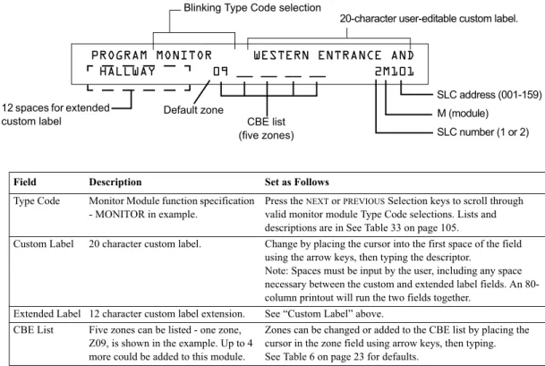
How to Modify an Addressable Monitor Module Point
When you select a point address, the control panel returns a screen that displays information about the point. Below is an example of information for a monitor module (2M101) in the LCD display:
Table 5 Modifying Monitor Module Programming Selections
Modifying Control Module Programming Selections
When finished modifying a point, press the ENTER key; then press the NEXT or PREVIOUS key to select another point.
Monitor Module Default Zone Assignments
Listing of the monitor module address range and the default zone assignment for each range:
Table 6 Monitor Module Default Zones
Field Description Set as Follows
Type Code Monitor Module function specification - MONITOR in example.
Press the NEXT or PREVIOUS Selection keys to scroll through valid monitor module Type Code selections. Lists and descriptions are in See Table 33 on page 105.
Custom Label 20 character custom label. Change by placing the cursor into the first space of the field using the arrow keys, then typing the descriptor.
Note: Spaces must be input by the user, including any space necessary between the custom and extended label fields. An 80-column printout will run the two fields together.
Extended Label 12 character custom label extension. See “Custom Label” above. CBE List Five zones can be listed - one zone,
Z09, is shown in the example. Up to 4 more could be added to this module.
Zones can be changed or added to the CBE list by placing the cursor in the zone field using arrow keys, then typing. See Table 6 on page 23 for defaults.
Monitor Module Address Zone Default
01 through 19 Z04
20 through 39 Z05
40 through 59 Z06
60 through 79 Z07
80 through 99 Z08
100 through 119 Z09 120 through 139 Z10 140 through 159 Z11
Default zone
Blinking Type Code selection
CBE list (five zones) 12 spaces for extended
custom label
SLC number (1 or 2) M (module)
SLC address (001-159)
PROGRAM MONITOR WESTERN ENTRANCE AND
HALLWAY 09 __ __ __ __ 2M101
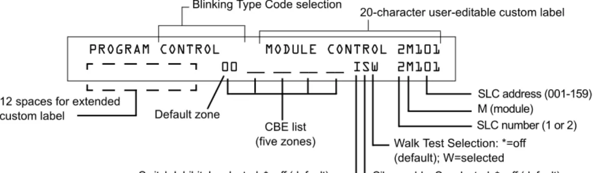
How to Modify an Addressable Control Module Point
When you select a point address for modification, the control panel returns a screen that displays information about the point. For example, the illustration below shows sample information for a control module (2M101) in the LCD display.
To modify a point, follow these steps:
Note: A blinking cursor indicates the selected field.
1. From the programming screen, use the arrow keys to move to a field that you want to modify. See below for descriptions and settings.
Table 7 Modifying Control Module Programming Selections
2. When finished modifying a point, press the ENTER key; then press the NEXT or PREVIOUS key to select another point.
Field Description Set as follows:
Type Code Specifies the function of the control module Press the NEXT or PREVIOUS Selection keys to scroll through valid control module Type Code selections (listed in Table 34 on page 106)
Custom Label 20 character custom label. Change by placing the cursor into the first space of the field using the arrow keys, then typing the descriptor.
Note: Spaces must be input by the user, including any space necessary between the custom and extended label fields. An 80-column printout will run the two fields together. Extended Label 12 character custom label extension. See “Custom Label” above.
CBE list Up to five software zones can be entered to define the output responses of the control module based on various initiating conditions (events)
Type the number of up to five zones, including E0-E9, F0-F9, L0-L9, R0-R9, and zones 00-99. The first zone default is Z00 (general alarm).
Switch Inhibit Specifies if an operator can manually activate an output
Type one of the following entries. I = Switch Inhibit enabled
* = no switch inhibit (default for all but releasing circuits) Silenceable Specifies if an operator can manually silence
an activated output
Type one of the following entries. * = output nonsilenceable
F = silenceable, resound by fire alarm U = silenceable, resound by supervisory alarm B = silenceable, resound by security alarm T = silenceable, resound by trouble O = silenceable, does not resound
Note: If the “Strobe” Type ID is used with System Sensor Strobe synchronization, F, U, B, T, or O will silence the entire circuit, “*” will silence the horn portion only. Walk Test Specifies if outputs sound during Walk Test Type one of the following entries.
W = devices sound (Basic Walk Test)
* = devices do not sound (Silent Walk Test) (default)
Walk Test Selection: *=off (default); W=selected
Silenceable: S=selected; *=off (default)
Note: On a control module, the default zone
is always set to Zone 00 (general alarm). Default zone
Blinking Type Code selection
CBE list (five zones) 12 spaces for extended
custom label
SLC number (1 or 2) M (module)
SLC address (001-159)
Switch Inhibit: I=selected; *=off (default)
PROGRAM CONTROL MODULE CONTROL 2M101
00 __ __ __ __ ISW 2M101
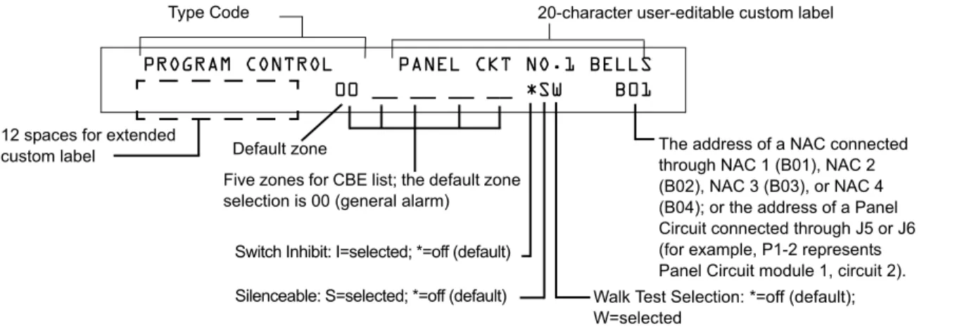
How to Modify NAC and Panel Circuit Points
Modifying NAC (four NACs on the NFS-640) and Panel Circuits (connected through J5 or J6) is like modifying control modules—except for the Type Code and device address.
To modify a point, follow these steps:
Note: A blinking cursor indicates the selected field.
1. From the programming screen, use the arrow keys to move to a field that you want to modify and refer to information below for descriptions and settings.
Table 8 Modifying a NAC/Panel Circuit Programming Selections
2. When finished modifying a point, press the ENTER key; then press the NEXT or PREVIOUS key to select another point.
The address of a NAC connected through NAC 1 (B01), NAC 2 (B02), NAC 3 (B03), or NAC 4 (B04); or the address of a Panel Circuit connected through J5 or J6 (for example, P1-2 represents Panel Circuit module 1, circuit 2). Five zones for CBE list; the default zone
selection is 00 (general alarm)
PROGRAM CONTROL PANEL CKT NO.1 BELLS
00 __ __ __ __ *SW B01
Default zone 12 spaces for extended
custom label
Switch Inhibit: I=selected; *=off (default)
Walk Test Selection: *=off (default); W=selected
Silenceable: S=selected; *=off (default)
Type Code 20-character user-editable custom label
Field Description Set as follows:
Type Code Specifies the function of the NAC or Panel Circuit
Press the NEXT or PREVIOUS Selection keys to scroll through the NAC or Panel Circuit Type Code selections (listed in Table 35 on page 107)
Custom Label 20 character custom label. Change by placing the cursor into the first space of the field using the arrow keys, then typing the descriptor.
Note: Spaces must be input by the user, including any space necessary between the custom and extended label fields. An 80-column printout will run the two fields together. Extended Label 12 character custom label extension. See “Custom Label” above.
CBE zones Specifies up to five software zones to define the output responses of the NAC or Panel Circuit based on various initiating conditions (events)
Type the numbers of up to five zones, including E0-E9, F0-F9, L0-L9, R0-R9, and zones 00-99. The first zone default is 00 (general alarm)
Switch Inhibit Specifies if an operator can manually activate an output
Type in one of the following values. I = Switch Inhibit enabled
* = Switch Inhibit disabled (default for all but releasing circuits)
Silenceable Specifies if an operator can manually silence an activated output
Type in one of the following values. * = output nonsilenceable
F = silenceable, resound by fire alarm U = silenceable, resound by supervisory alarm B = silenceable, resound by security alarm T = silenceable, resound by trouble O = silenceable, does not resound Walk Test Specifies if outputs sound during Walk Test Type in one of the following values.
W = devices sound (Basic Walk Test) - default * = devices do not sound (Silent Walk Test)
How to Change a Password (3=
PASSWD)
Password Change lets you select a custom Program Change (high level) or Status Change (low level) password. From the “Basic Program” screen, press the 3 key
to display the “Change Password” screen.
.
To change a password, follow the instructions below:
A Forgotten Password?
If a password is entered incorrectly, the panel will respond by displaying an INCORRECT PASSWORD message and a code. The programmer may hit escape and reenter the password correctly. However, if the password has been forgotten, record the code and contact Notifier. After proper authentication, the original password can be determined by deciphering the code. An example of an INCORRECT PASSWORD display is given below:
To Press Then
Change the Program Change password
Enter the new Program Change password. Use five digits, no characters. Change the Status Change
password
Enter the new Status Change password. Use five digits, no characters.
Save the password The Verify Password screen appears. Press ENTER to verify.
Leave the Change Password screen without changing a password
The Basic Program screen appears. Program Change
Password
CHANGE PASSWORD *,NNNNN,E=PROGRAM
#,NNNNN, E=STATUS
Entry area for new password
INCORRECT PASSWORD
PROGRAM: 9066-21F5-7D78-5FA4-6163
How to Create a System Message (4=
MESSAGE)
The Message option lets you create a 40-character custom System Message that displays on the first line of the “SYSTEM NORMAL’ screen as shown below:
From the “Basic Program” screen, press the 4 key to display the “System Message Change” screen:
To create the system message, follow these guidelines:
• Enter one character at a time, indicated by the blinking cursor on the second line of the display. • Enter up to 40 characters maximum.
Instructions for entering characters in the Message Change screen:
To Do this
Change a blinking character Enter a character from the keypad Move to the next character
Press Enter lower case characters
Press , then press the character of your choice. Enter additional characters
(! @ = , % : \ . I ? ) Press , then press a number key as follows:
For example, press , then press the 3 ( ) key to enter a “=” character.
Save the new message
Press Program Change
Password
YOUR CUSTOM MESSAGE HERE
SYSTEM NORMAL 02:24P 110100 Wed
Blinking cursor prompt Message change area
How to Create a Custom Zone Label (5=
ZONE)
The Zone option lets you change the custom label assigned to zones 1-99. From the “Basic Program” screen, press the 5 key to display the “Zone Change” screen
as shown below:
The zone number displays in the first line, characters 39 and 40. When changing a zone label, follow these guidelines.
• For single-digit numbers, enter a leading zero before the digit.
• Enter an alphanumeric zone label into line 2, characters 21–40. The program forces a blank for the first character, which inserts a space between the device and zone labels for a printout. To change a custom label for a zone, follow these instructions:
To Do this
Change a zone label Enter a new zone label from the keypad. Save the zone label in memory
Press .
The program stores the zone label in memory and displays the Zone Change screen with all fields blank. Leave the Zone Change screen
without changing a zone label Press .
The display returns to the Program Change screen. Program Change
Password
CHANGE ZONE LABEL SELECT ZONE 01-99:
ENTER UP TO 20 CHAR
blinking cursor prompt
How to Program Special Zones (6=SPL FUNCT)
The Special Zone Change option lets you change the program for Special Zones F0-F9 or Releasing Zones R0-R9. From the “Basic Program” screen, press the
6key to display the “Special Function Change” screen as shown below:
.
What are Special Zones?
Descriptions for each Special Zone that appears in the “Special Function Change” screen are detailed below:
Note: Special Zones F0-F9 appear in the CBE list of device as ZF0-ZF9. For example, if you list F0 for a detector, one
of the five zones in the CBE list of the detector will display as ZF0.
Table 9 Summary of Special Zones
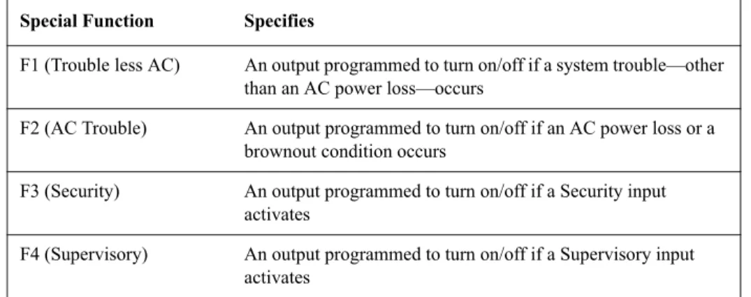
The control panel also provides four Special Zones, F1-F4, which are outputs that do not appear on the Special Function Change screen. You can program Special Zones F1 to F4 into the CBE of an output device. Descriptions of F1, F2, F3, and F4 are detailed below:
Note: To view the status of Special Functions F1-F4, use the Read Status function (refer to the NFS-640 Operations
Manual).
Table 10 Special Output Functions F1-F4
Special Zone Lets you
F0=PRESIG Select a Presignal Delay Timer and select PAS (Positive Alarm Sequence)
F5-F6=TIME Specify Time Control functions such as the start time, stop time, or days of the week
F7=HOL Specify up to nine holiday dates. An F7-programmed device activates on the specified holiday dates
F8=CODE Specify one of seven coding function selections: March Time, Temporal, California, Two-Stage, Canadian Two-Stage (3 minute or 5 minute), or System Sensor Strobes. F8 only takes effect if you program one or more NACs to F8
F9=PRE-ALARM Select a Pre-Alarm level: Alert or Action
R0-R9=REL Program up to ten Releasing Zones, each with a selection for a
Delay Timer, an Abort Switch, a Cross Zone selection, or a Soak Timer
Special Function Specifies
F1 (Trouble less AC) An output programmed to turn on/off if a system trouble—other than an AC power loss—occurs
F2 (AC Trouble) An output programmed to turn on/off if an AC power loss or a brownout condition occurs
F3 (Security) An output programmed to turn on/off if a Security input activates
F4 (Supervisory) An output programmed to turn on/off if a Supervisory input activates
Program Change Password
SPECIAL FUNCTION: F0=PRESIG R0-R9=REL
How to Select Special Zones
Select Special Zones by entering the Special Zone letter and number (for example, F0, R0, and so on) from the Special Function Change screen. The following sections show sample screens that display when you select a Special Zone.
F0 (Presignal/PAS) The Presignal screen provides fields for changing the delay time or PAS. For details on Presignal selections, refer to “Presignal and Positive Alarm Sequence (PAS)” on page 80. From the Special Function Change screen, press the F key, then press the 0key to display the Presignal Function screen.
R0-R9 (Releasing Functions) The Releasing Function screen provides fields for changing releasing functions: Delay Timer, Abort Switch, Cross Zone, and Soak Timer. For details on releasing
applications, refer to “Appendix A: Releasing Applications” on page 53. From the Special Function Change screen, select a function (R0-R9) to display the Releasing Function screen:
F5-F6 (Time Control Functions) The Time Control screen provides fields for changing the start time, stop time, or days of the week. For details on time selections, refer to “Time Control Zones” on page 82. From the Special Function Change screen, select F5 or F6 to display the Time Control screen:
Continued on the next page... Presignal delay time:
60-180 seconds or OFF
(no Presignal selected) PAS selection: YES (PAS selected) or NO (PAS not selected)
Presignal programming status banner
Presignal (zone F0)
PRG PRESIGNAL FUNCT PRESIGNAL DELAY
DELAY=180 PAS=NO F00
Delay Timer for releasing application: 1-60 seconds or 00 (no delay)
Releasing Zone programming status banner
Abort Switch: a thee-letter Abort switch Type Code (ULI, IRI, NYC, or AHJ)
Cross Zone option: specifies type of Cross Zone: N (none), Y, Z, or H
Soak Timer option:0000 (not used) or delay time (0001-9999 seconds)
Releasing zone (R0 shown)
PRG RELEASE FUNCT RELEASE CONTROL
DELAY=00 ABORT=ULI CROSS=N SOK=0000 R00
Time Control programming status banner
Time Control zone (F5 shown)
Eighth day-of-week selection (H) that specifies when time control settings take effect. Press the NEXT or PREVIOUS key
to toggle each selection. ON time: Start Time for Time Control
function (in 24-hour time) that must precede the OFF time.
OFF time: End time for Time Control function (in 24-hour time) that must be later than the ON time.
PRG TIME FUNCTION TIME CONTROL
F7 (Holiday) The Holiday screen provides fields for specifying up to nine holiday dates. For details on holiday selections, refer to “Time Control Zones” on page 82. From the Special Function Change screen, press F7 to display the Holiday screen:
F8 (Coding Function) The Coding Function screen provides fields for specifying one of seven coding functions: March Time, Two-stage, California, Temporal, Canadian Two-Stage (3 minutes), Canadian Two-Stage (5 minutes), and System Sensor Strobe. For details on selecting coding functions, refer to “Coding Functions for NACS and Panel Circuits” on page 82. From the Special Function Change screen, press F8 to display the Coding Function screen:
F9 (Pre-Alarm) The Pre-Alarm screen provides fields for programming the Alert or Action Pre-Alarm functions. For details on Pre-Alarm selections, refer to “Pre-Alarm” on page 88. From the Special Function Change screen, press F9 to display the Pre-Alarm screen:
Holiday programming status banner
Nine fields for selecting holidays: USA time (mm/dd)
PRG HOLIDAY FUNC **/** **/** **/**
**/** **/** **/** **/** **/** **/**
Coding Function selection (refer to “Coding Functions for NACS and Panel Circuits” on page 82)
Coding Function programming status banner
Coding Function (Zone F8)
PRG CODING FUNCTION CODE TYPE
MARCH TIME F08
ACTION or ALERT Pre-Alarm level: press the NEXT or PREVIOUS
key to toggle between ALERT and ACTION. For details on selections, refer to “How to Select a Pre-Alarm Level” on page 89)
Pre-Alarm (Zone F9) Pre-Alarm programming
status banner
PRG PRE-ALARM FUNCT ALERT
How to Change Global System Functions (7=
SYSTEM)
The System option lets you select settings for global system functions that apply to all programmed devices and zones. For instance, selecting an Alarm
Verification Timer for 30 seconds means that all initiating devices selected for Alarm Verification use a 30-second timer. From the “Basic Program” screen, press the 7 key to display the “System Function” screen as shown below:
Global System Functions
Settings for global system functions:
Table 11 Settings for Global Systems Functions
System Function Setting Default
SIL INH (Silence Inhibit Timer) 0 to 300 seconds 000 AUTO (Auto Silence Timer) - After the time
delay expires, functions like pressing the SIGNAL SILENCE key, silencing active outputs programmed as silenceable.
000 (none); 600 to 900 seconds 000
VERIFY (Alarm Verification Timer) 0 to 60 seconds* 60
USA TIME USA time (mm/dd/yy) or
EUR time (dd/mm/yy)
Press the NEXT or PREVIOUS key to change. Note that (European) time changes to 24-hour time format and date format.
USA
TERM - Allows supervision for devices connected to TB12, i.e., LCD-80.
N = no supervision Y = supervision enabled
N AC_DLY AC delay – delays loss of AC reporting for
8 hours.
Y=AC delay; N=no AC delay
Y
LocX - One of three operating modes of PC or terminal connected to the control panel through TB15 on the CPU-640.
Note: For a complete list of functions, refer to the NFS-640 Operations Manual.
LocT -(terminal connected to control panel and located in same room). LocM -(same as LocT but requires password).
RemT -(terminal connected through a modem for Read Status only).
LocT
BLINK - Addressable SLC device LED blink. Select from 00 to 16.
(00 = no blink, 01 = blink every poll, 02 = blink every 2nd poll, 03 = blink every 3rd poll up to 16 = blink every 16th poll). Note: This setting affects FlashScan modules only.
01
ST - The NFPA wiring style used for the SLC. 6=Style 6 SLC wiring 4=Style 4 SLC wiring
4 ACS - Use ACS Selection Groups (Refer to
“Annunciator Options” on page 33).
N or Y N
*This value can not exceed 30 seconds for ULC installations. Program Change
Password
SIL INH=000 AUTO=000 VERIFY=30 USA TIME TERM=N AC_DLY=Y LocT BLINK=01 ST=4 ACS=N
Annunciator Options
Use Annunciator Selection screens to select information that will display on the ACS annunciators. (Table 12 on page 34 contains the ACS display selections.) Setting ACS=Y from the “System Function” screen displays the Annunciator Selection 1 screen, address A1 - A11. Press enter to display
Annunciator Selection 2 screen, address A12 - A19:
Enter “N” (ACS Selection Group N) for a TM-4 module used for remote station communication. Enter “O” (ACS Selection Group O) for a TM-4 used as a municipal box trip. This will provide a “Master Box” trouble message at the panel.
Refer to page 40 for further information on Group N and Group O.
ACS Selection Group Example
An example of a screen listing ACS Selection Groups (H, I and M):
Annunciator selections for addresses A1, A2 and A3 (addresses A4-A11 not selected).
• Annunciators set to Address 1 display the status of detectors 1-64 (Group H) on SLC 1 • Annunciators set to Address 2 display the status of detectors 1-64 (Group I) on SLC 2 • Annunciators set to Address 3 display the status of the Panel Circuit modules (Group M)
ACS Address A1-A11
ACS Selection Group (A-M; 0-9) or *=not selected
If UDACT=Y: Addresses A20-A32 are available with UDACTs having software release #UDACT02.1 or higher to send control panel status to aUDACT.
If UDACT=N: The control panel displays the Annunciator Selection 3 & 4 screen addresses A20-A32.
ACS Address A12-A19
ANNUN SELECTION1 A1=* A2=* A3=* A4=*
A5=* A6=* A7=* A8=* A9=* A10=* A11=*
ANNUN SELECTION2 A12=* A13=* A14=*
A15=* A16=* A17=* A18=* A19=* UDACT=N
ACS Address (A1) ACS Selection Group (H)
ANNUN SELECTION1 A1=H A2=I A3=M A4=*