An Improved Performance Of Pid And Fuzzy Controller
Based Sapf For Wind And Solar Power Generation
1T.Bhaskara Rao2B.Aditya Kumar,3K.Ramana Babu 1M-tech Student Scholar,2Assistant Professor,3Assistant Professor
Department of Electrical & Electronics Engineering,
Prasiddha College Of Engineering&Technology (PCET) East Godavari (Dist.); A.P, India Email.id:[email protected];[email protected];[email protected]
Abstract:
Amid the previous existences a while, fuzzy controller depends on fuzzy logic included manages in a sure level of ideas can't be communicated as the " genuine" or "false" however a bit "in part genuine" are most dynamic and productive ranges for examination arranged applications particularly in the domain of mechanical procedure of data yield relations. The compensator is proposed for use with every individual distributed span (DS) framework in the smaller scale matrix, and comprises of two four -leg inverters (an arrangement and a shunt), ideally controlled to accomplish an improvement of both the nature of force inside of the miniaturized scale network and the nature of streams existing between the small scale lattice and usage framework. The reason for a four-leg voltage-source inverter (4LVSI) allow the pay of current consonant fixings, incorporating unequal current created in single-stage nonlinear burdens. An exact straightforward numerical model of shunt dynamic channel, including the impact of force framework impedance, is give and used to outline the prescient control calculation. The essential pay of the proposed shunt dynamic force channel and took after control plan for relentless state and transient occurrence conditions is displays for the nature of force through test results by MATLAB/SIMULINK.
Key words: Fuzzy controller, shunt active power filter, control of harmonics, predictive current control; four leg converters, and power improvement. I. Introduction
Presently a day's Renewable energy sources (RESs) have encountered a fast development in Power era because of mechanical enhancements, which have continuously decreased their expenses and expanded their proficiency in the meantime to achieve force request according to the necessity of force usage over the topographical ranges. Be that as it may, renewable energy era includes power quality because of its non-linearity, so this non-linearity conduct of force era specifically changes the voltage regulation
and makes an issue of voltage bending in force frameworks. The need to coordinate the renewable energy like wind energy/PV into force framework is to make it conceivable to minimize the ecological effect on customary plant [1]. The coordination of wind energy into existing force framework presents specialized difficulties and that requires thought of voltage regulation, steadiness, and power quality issues. The force quality is a key client centered measure and is significantly influenced by the operation of a conveyance and transmission system. The issue of force quality is of extraordinary significance to the wind turbine there has been a broad development and speedy advancement in the abuse of wind energy as of late.
piece of the dynamic force channel configuration and the force framework impedance is acquired from surely understood standard strategies. On account of obscure framework impedance parameters, an estimation strategy can be utilized to infer a precise R–L equal impedance model of the framework. Routinely, PI, PD and PID controller are most mainstream controllers and generally utilized as a part of most power electronic apparatuses however as of late there are numerous specialists reported effectively embraced Fuzzy Logic Controller (FLC) to wind up one of shrewd controllers to their machines [3]. Concerning their effective philosophy execution, this sort of procedure actualized in this paper is utilizing fuzzy rationale controller with input by presentation of voltage separately. The presentation of progress in voltage in the circuit will be encouraged to fuzzy controller to give suitable measure on unfaltering state signal. The fuzzy rationale controller serves as shrewd controller for this propose. This paper shows the numerical model of the 4L-VSI and the standards of operation of the proposed prescient control plan, including the configuration system. The complete portrayal of the chose current reference generator actualized in the dynamic force channel is likewise displayed. At last, the proposed dynamic force channel and the adequacy of the related control plan pay, power quality change is reenacted utilizing MATLAB/SIMULINK.
II. Hybrid Power System With Four -Leg Converter Model
Fig 1 shows the typical power distribution system having other types loads and different generation units, such as wind and solar (or) sunlight, used to produce electricity for residential (or) domestic purpose and small industries.
Fig.1 hybrid power generation system with a Shunt active power filter.
Both wind and solar types of power generation use ac/ac and dc/ac static PWM converters for voltage conversion and battery banks for more energy storage. The PWM converters perform to cover the maximum power tracks to extract the large amount of energy from wind and solar. The consumption of
electrical energy may be balanced or unbalanced, single or three phase and linear or nonlinear [8].
Fig.2.Three-phase equivalent circuit shunt active power filter.
The active filter is connected to the system in parallel at the point of common coupling(PCC) to take care of current harmonics, current unbalance and reactive power[2]. The shunt active filter performed by an electrolytic capacitor with a four leg PWM converter, and 1st order ripple factor as shown in fig.2 with source impedance (Zs), filter impedance (Zf) and the load impedance (ZL). The four leg PWM converter topology is shown in fig.3. This converter model is similar to the conventional three-phase converter with fourth leg connected to neutral bus of the system acts as a two level system of PWM Topology[21].
Fig. 3. Two-level four-leg PWM-VSI topology.
By the addition of fourth leg to the three-phase conventional converter , increases switching states from improving control flexibility and output quality .and is well advisable for current unbalanced compensation. The voltage at any leg ‘x’ in the 4-leg converter measures from the neutral point (n), can be written as in terms of switching states in this manner
The mathematical model of the the filter derived from equivalent circuit shown in fig .2 is
Thevenin’s equivalent impedance is determined by a series connection of the ripple filter impedance Zf and a parallel arrangement between the system equivalent impedance Zs and the load impedance ZL.
For this model, it is assumed that ZL _ Zs , that the resistive part of the system’s equivalent impedance is neglected, and that the series reactance is in the range of 3–7% p.u., which is an acceptable approximation of the real system. Finally,
Req = Rf and Leq = Ls + Lf.
III. Current Control Scheme
The sectional diagram of current control scheme is shown in Fig .4 .The current control proposal is basically required to current references, that are used to compensates the undesirable load components. In this section the source voltage, load current and the dc-voltage converter are measured, while the natural currents are generated exactly from the current reference generator.
Fig.4.Current control block diagram.
A converter is used to predict the output converter current, Both controller and system converter must be represented as predictive model for knowing switching states and control variables. A dq-based current reference generator scheme is used to get the active power filter current reference signals. This design gives a fast and accurate signal tracking capability. The dq current reference signal affecting the compensation performance, to avoided voltage flections as well as total harmonic distortions of the voltage. The displacement power factor (sin φ(L) ) and the maximum total harmonic distortion of the load (THD(L) ) defines the relationships between the apparent power required by the active power filter, with respect to the load, as shown
Where the value of THD(L) includes the maximum compensable harmonic current, defined as double the sampling frequency fs. The frequency current harmonic component that can be compensated is equal to one half of the converter switching frequency. By using dq-transformation, the d current
component is synchronized with the corresponding phase-to-neutral system voltage, and the q current component is phase-shifted by 90◦.The dq-based scheme operates in a rotating reference frame; therefore, the measured currents must be multiplied by the sin(wt) and cos (wt) signals. The sin(wt) and cos (wt) synchronized reference signals are obtained from a synchronous reference frame (SRF) PLL [21]. The SRFPLL generates a pure sinusoidal waveform even when the system voltage is severely distorted. Tracking errors are eliminated, since SRF-PLLs are designed to avoid phase voltage unbalancing, harmonics (i.e., less than 5% and 3% in fifth and seventh, respectively), and offset caused by the nonlinear load conditions and measurement errors [3], the relationship between the real currents iLx(t) (x = u, v,w) and the associated dq components (id and iq)
Fig.5.dq-based current reference generator block diagram.
The current that flows through the neutral of the load is compensated by injecting the same instantaneous value obtained from the phase-currents, phase-shifted by 180°, as shown.
One of the major advantages of the dq-based current reference generator scheme is that it allows the implementation of a linear controller in the dc-voltage control loop. However, one important disadvantage of the dq-based current reference frame algorithm used to generate the current reference is that a second order harmonic component is generated in id and iq under unbalanced operating conditions. The amplitude of this harmonic depends on the percent of unbalanced load current (expressed as the relationship between the negative sequence current iL,2 and the positive sequence current iL,1 ). The second-order harmonic cannot be removed from id and iq , and therefore generates a third harmonic in the reference current when it is converted back to abc frame [17]. Since the load current does not have a third harmonic, the one generated by the active power filter flows to the power system.
A. DC Link Voltage Control
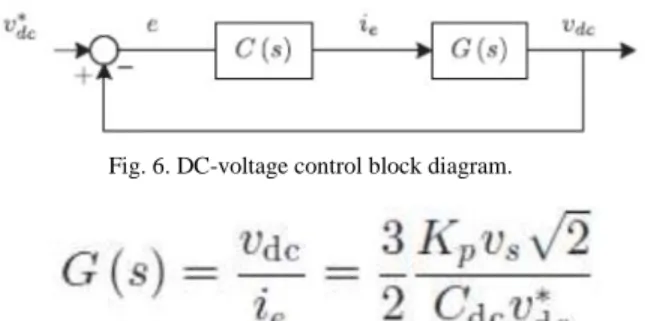
The dc-voltage converter is controlled with a traditional PID controller. This is an important issue in the evaluation, since the cost function is designed using only current references, in order to avoid the use of weighting factors. Generally, these weighting factors are obtained experimentally, and they are not well defined when different operating conditions are required. Additionally, the slow dynamic response of the voltage across the electrolytic capacitor does not affect the current transient response. For this reason, the PID controller represents a simple and effective alternative for the dc-voltage control. The dc-voltage remains constant (with a minimum value of sqrt of 6vs(rms) ) until the active power absorbed by the converter decreases to a level where it is unable to compensate for its losses. The active power absorbed by the converter is controlled by adjusting the amplitude of the active power reference signal ie , which is in phase with each phase voltage. In the block diagram shown in Fig. 5, the dc-voltage vdc is measured and then compared with a constant reference value v*dc. The error (e) is processed by a PID controller, with gains, Kp and Ti. Both gains are calculated according to the dynamic response requirement. Fig. 6 shows that the output of the PID controller is fed to the dc-voltage transfer function Gs Which is represented by a first-order system.
Fig. 6. DC-voltage control block diagram.
The equivalent closed-loop transfer function of the given system with a PID controller. Since the time response of the dc-voltage control loop does not need to be fast, a damping factor ζ = 1and a natural angular speed ωn = 2π · 100 rad/s are used to obtain a critically damped response with minimal voltage oscillation. The corresponding integral time Ti = 1/a (13) and proportional gain Kp can be calculated as
IV.
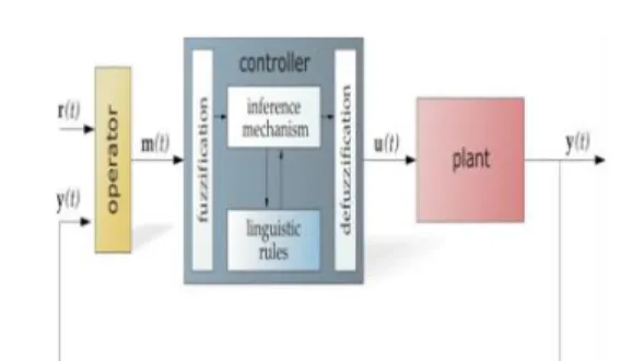
Fuzzy Logic ControllerFig.7 General Structure of the fuzzy logic controller.
The basic scheme of a fuzzy logic controller is shown in Fig 7.and consists of four principal components such as: a inference mechanism, which converts input data into suitable linguistic values; a knowledge base, which consists of a data base with the necessary linguistic definitions and the control rule set; a decision-making
logic which, simulating a human decision process, infer the fuzzy control action from the knowledge of the control rules and linguistic variable definitions; a de-fuzzification interface which yields non fuzzy control action from an inferred fuzzy control action [10]. The fuzzy control systems are based on expert knowledge that converts the human linguistic concepts into an automatic control strategy without any complicated mathematical model.
Fig. 8 Block diagram of the Fuzzy Logic Controller (FLC) for proposed converter
Fig.9. Hysteresis current modulation. With the hysteresis control, limit bands are set on either side of a signal representing the desired output waveform [6]. The inverter switches are operated as the generated signals within limits. The control circuit generates the sine reference signal wave of
desired magnitude and frequency, and it is compared with the actual signal. As the signal exceeds a prescribed hysteresis band, the upper switch in the half bridge is turned OFF and the lower switch is turned ON. As the signal crosses the lower limit, the lower switch is turned OFF and the upper switch is turned ON. The actual signal wave is thus forced to track the sine reference wave within the hysteresis band limits.
V. Matlab Modeleing And Simulation Results
Fig.10 Simulink/ Mat lab model for proposed RES 4-leg SAPF system with Fuzzy controller.
Results: Proposed SAPF with Knowledge based
Fuzzy Controller
Fig.11 Simulation results for SAPF with Fuzzy Controller (a) Source Voltage. (b) Load current. (c) Compensator Current.
(d) Neutral Current, (e) Source Current (f) DC Link Voltage.
In Fig.11 shows Simulation results for SAPF knowledge based with Fuzzy Controller (a) Source Voltage. (b) Load current. (c) Compensator Current, (d) Neutral Current, (e) Source Current (f) DC Link Voltage. Here compensator is turned on at 0.05 seconds, before we get some harmonics coming from nonlinear load, then distorts our parameters and get sinusoidal when compensator is in on.
Fig.12 Power Factor for SAPF with Fuzzy Controller
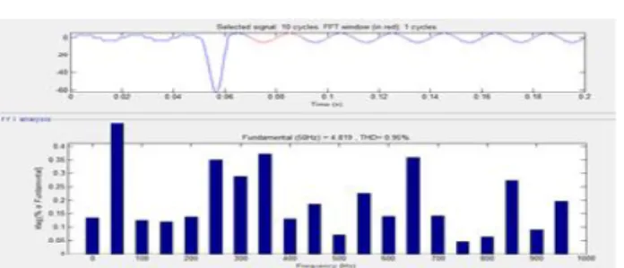
Fig.13 shows the FFT Analysis of Phase-A Source Current with Fuzzy Controlled SAPF, here we get 0.95%.
2. Proposed RES Fed SAPF with PID Controller
Fig.14 Matlab/simulink model for RES SAPF system with PID controller.
Fig.15 Simulation results for SAPF with Formal PID Controller (a) Source Voltage. (b) Load current. (c) Compensator Current. (d) Neutral Current, (e) Source Current (f) DC Link Voltage.
Fig.15 Simulation results for SAPF with Formal PID Controller (a) Source Voltage. (b) Load current. (c) Compensator Current, (d) Neutral Current, (e) Source Current (f) DC Link Voltage. Here compensator is turned on at 0.05 seconds, before we get some harmonics coming from non-linear load, then distorts our parameters and get sinusoidal when compensator is in on.
Fig.16 Power Factor for SAPF with Conventional PID Controller
Fig. 16 shows the power factor it is clear from the figure after compensation power factor is unity.
Fig. 17 FFT Analysis of Phase-A Source Current with PID Controlled SAPF
Fig.17 shows the FFT Analysis of Phase-A Source Current with PID Controlled APF, here we get 2.52%.
VI. Conclusion
This paper presents power quality change of the circulation framework with 4-L SAPF in light of Predictive control activity. Enhanced element current sounds and a responsive force pay plan for force circulation frameworks with era from renewable sources has been proposed to enhance the present nature of the dissemination framework. Points of interest of the proposed plan are identified with its effortlessness, demonstrating, and usage. This paper has displayed a novel control of a current RES interfacing SAPF utilizing customary PID controller and fluffy rationale controller to enhance the nature of force at PCC for a 3-stage 4-wire framework. It has been demonstrated that the SAPF framework can be adequately used for force molding without influencing its ordinary operation of genuine force exchange. By utilizing routine controller we get THD worth is 2.52%, however utilizing the fluffy rationale controller THD worth is 0.95%.controller and fluffy rationale controller to enhance the nature of force at PCC for a 3-stage 4-wire framework. It has been demonstrated that the SAPF framework can be successfully used for force molding without influencing its typical operation of genuine force exchange. By utilizing customary controller we get THD worth is 2.52%, however utilizing the fluffy rationale controller THD quality is 0.95%.
References
[1] J. Rocabert, A. Luna, F. Blaabjerg, and P. Rodriguez, “Control of power converters in AC microgrids,” IEEE Trans. Power Electron., vol.27, no. 11, pp. 4734–4749, Nov. 2012.
[2] M. Aredes, J. Hafner, and K. Heumann, “Three -phase four-wire shuntactive filter control strategies,”
IEEE Trans. Power Electron., vol. 12, no 2, pp. 311– 318, Mar. 1997.
[3] S. Naidu and D. Fernandes, “Dynamic voltage restorer based on a fourleg voltage source converter,”
Gener. Transm. Distrib., IET, vol. 3, no. 5, pp. 437– 447, May 2009.
three-phase four-leg VSI topology to compensate nonlinear load,” IEEE Trans. Power Electron., vol. 25, no. 8, pp. 1935–1942, Aug. 2010.
[5] G.Satyanarayana., K.N.V Prasad, G.Ranjith Kumar, K. Lakshmi Ganesh, "Improvement of power quality by using hybrid fuzzy controlled based IPQC at various load conditions," Energy Efficient Technologies for Sustainability (ICEETS), 2013 International Conference on , vol., no., pp.1243,1250, 10-12 April 2013..
[6] F. Wang, J. Duarte, and M. Hendrix, “Grid -interfacing converter systems with enhanced voltage quality for microgrid application;concept and implementation,” IEEE Trans. Power Electron., vol. 26, no. 12, pp. 3501–3513, Dec. 2011.
[7] X.Wei, “Study on digital pi control of current loop in active power filter,” inProc. 2010 Int. Conf. Electr. Control Eng., Jun. 2010, pp. 4287–4290. [8] R. de Araujo Ribeiro, C. de Azevedo, and R. de Sousa, “A robust adaptive control strategy of active power filters for power-factor correction, harmonic compensation, and balancing of nonlinear loads,”
IEEE Trans. Power Electron., vol. 27, no. 2, pp. 718– 730, Feb. 2012.
[9] J. Rodriguez, J. Pontt, C. Silva, P. Correa, P. Lezana, P. Cortes, and U. Ammann, “Predictive current control of a voltage source inverter,” IEEE Trans. Ind. Electron., vol. 54, no. 1, pp. 495–503, Feb. 2007.
[10] Satyanarayana, G.; Ganesh, K.Lakshmi; Kumar, Ch. Narendra; Krishna, M.Vijaya, "A critical evaluation of power quality features using Hybrid Multi-Filter Conditioner topology," Green Computing, Communication and Conservation of Energy (ICGCE), 2013 International Conference on , vol., no., pp.731,736, 12-14 Dec. 2013.
[11] R. Vargas, P. Cortes, U. Ammann, J. Rodriguez, and J. Pontt,
“Predictive control of a three-phase neutral-point-clamped inverter,” IEEE Trans. Ind. Electron., vol. 54, no. 5, pp. 2697–2705, Oct. 2007.
[12] P. Cortes, A. Wilson, S. Kouro, J. Rodriguez, and H. Abu-Rub, “Model predictive control ofmultilevel cascaded H-bridge inverters,” IEEE Trans. Ind. Electron., vol. 57, no. 8, pp. 2691–2699, Aug. 2010.
[13] P. Lezana, R. Aguilera, and D. Quevedo, “Model predictive control of an asymmetric flying capacitor converter,”IEEE Trans. Ind. Electron. vol. 56, no. 6, pp. 1839–1846, Jun. 2009.
[14] P. Correa, J. Rodriguez, I. Lizama, and D. Andler, “A predictive control scheme for current-source rectifiers,” IEEE Trans. Ind. Electron., vol. 56, no. 5, pp. 1813–1815, May 2009.
[15] M. Rivera, J. Rodriguez, B. Wu, J. Espinoza, and C. Rojas, “Currentcontrol for an indirect matrix
converter with filter resonance mitigation,” IEEE Trans. Ind. Electron., vol. 59, no. 1, pp. 71–79, Jan. 2012.
[16] P. Correa, M. Pacas, and J. Rodriguez, “Predictive torque control for inverter-fed induction machines,”IEEE Trans. Ind. Electron., vol. 54, no. 2, pp. 1073–1079, Apr. 2007.
[17] M. Odavic, V. Biagini, P. Zanchetta, M. Sumner, and M. Degano,“Onesample- period-ahead predictive current control for highperformance active shunt power filters,”Power Electronics, IET, vol. 4, no. 4, pp. 414–423, Apr. 2011.
[18] IEEE Recommended Practice for Electric Power Distribution for Industrial Plants, IEEE Standard 141-1993, 1994
[19] R. de Araujo Ribeiro, C. de Azevedo, and R. de Sousa, “A robust adaptive control strategy of active power filters for power-factor correction, harmonic compensation, and balancing of nonlinear loads,”
IEEE Trans. Power Electron., vol. 27, no. 2, pp. 718– 730, Feb. 2012.
[20] M. Sumner, B. Palethorpe, D. Thomas, P. Zanchetta, and M. DiPiazza, “A technique for power supply harmonic impedance estimation using a controlled voltage disturbance,” IEEE Trans. Power Electron., vol. 17, no. 2, pp. 207–215, Mar. 2002. [21] S. Ali, M. Kazmierkowski, “PWM voltage and current control of four-leg VSI,” presented at the ISIE, Pretoria, South Africa, vol. 1, pp. 196–201, Jul. 1998
[22] S. Kouro, P. Cortes, R. Vargas, U. Ammann, and J. Rodriguez, “Model predictive control—A simple and powerful method to control power converters,”
IEEE Trans. Ind. Electron., vol. 56, no. 6, pp. 1826– 1838, Jun. 2009.
Authors:
T.Bhaskara Rao, M-tech Student Scholar, Department of Electrical & Electronics Engineering, Prasiddha College Of Engineering&Technology (Pcet)East Godavari (Dist.); A.P, India,Email.id: [email protected]
B.Aditya Kumar, M.Tech., Assistant Professor, Department of Electrical & Electronics Engineering, Prasiddha College Of Engineering & Technology (Pcet), East Godavari (Dist); A.P, India, Email.id: [email protected]