Abstract—In this paper, the application of Dominant Gain Concept for controlling time delay processes is considered from a new viewpoint. In this viewpoint, time delay is considered as function with infinite Right Half Plane (RHP) zeros which are transferred to the Left Half Plane by adding a proper transfer function to the open loop function. Furthermore, by defining a new concept, called minimum-gain frequency, the propositions for control system stability and the manner of choosing order and gain of the added transfer function are proved. Also, the application of this method is studied in order to simultaneously compensate for the Right Half Plane zeros and time-delay. Finally, easy application of this method is shown in an ordinary feedback loop as a PID controller.
Index Terms—Dominant gain, PID controller, Right half plane zeros, Time delay compensator.
I. INTRODUCTION
Many of processes in chemical industries suffer from time delay, because of which the input signal to controller also has delay and, therefore, the performance of control system is poor. To improve the control system performance, some predictors have been used [1]. The methods which have used predictors can be categorized into three classifications:
1. The methods which using a model, predict the time delay parameter and remove it from the open loop.
Smith predictor was the first attempt in this field [2]; however, it has been lately revealed that Smith's method is very sensitive with respect to the model mismatches, particularly the error in the time delay parameter [3-8]. Incapability of rejecting load disturbances in the control of processes with integration [9-10] and inability to control unstable processes [11] are the other problems mentioned for the Smith predictor. To solve these problems, many researchers have presented different methods called Dead Time Compensators (DTCs) [9-17]. The largest deficit of DTC-based methods is lack of their application for process models in which their transfer function are irrational and the time-delay cannot be factored out straightly from the transfer function. In order to solve this problem, Ramanathan et al [18-20], inspired by the Smith’s method, considered the time delay parameter as infinite Right Half Plane (RHP) zeros and divided the irrational transfer function (Ir-TF) model into two parts: Gp+(s): part of the model that includes RHP zeros and
Manuscript received March 28, 2011; revised May 30, 2011.
M.Esmaeli is with the National Petrochemical Company (corresponding author to provide phone: 0982184994273; fax: 09821880601290; e-mail: m.esmaeli@ nipc.net).
M. shirvani, is with the the Dept. of Chem. Eng., Iran University of Science & Technology (e-mail: [email protected]).
) (s
Gp− : part of the model that does not include RHP zeros. By compensating Gp+(s) from the open loop transfer function and input signal to the controller, the behavior of open loop was changed from non-minimum phase to minimum phase. This method was called Generalized Smith Predictor (GSP). In additional, Vollmer & Raisch [21-22] and Zĺtek & Hlava [23] controlled the processes with irrational models by using H∞ control and removing
) (s Gp
+ from the open loop.
2. The methods which predict input signal to the controller using a derivative mode in their controllers [24-26].
In these methods, controllers are considered either as equation (1) [24] or equation (2) [25] and some of the parameters are fixed at a typical value (as recommended in the textbooks on the process control) in order to limit the complexity of PID controller. For example, in [24] and [25],
d
i T
T =4 and N=10 are proposed.
s K s K K s
G i d
c( )= + +
(1)
) 1 1
1 ( ) (
+ + + =
s N T
s T s T K s G
d d i
c
(2)
The advantage of these methods is their easy applications in industrial control loops because 93% of the industrial control loops have PID controllers [27]. Also, it is shown that if time delay is small, the performance of a PID controller will be better than a DTC [25]. However, if a large time delay exists, a DTC will have a better performance than a PID.
3. These methods are a combination of the above two methods. In these methods, at first, the output signal of a DTC controller is identified using an identification system method and then the parameters of a PID controller are tuned so that its output signal will be the same as that of the DTC controller [28-29].
Because these methods need an identification method, they are seldom used in practice.
In [30], dominant gain concept is introduced based on the frequency response behavior of an irrational transfer function and in [31], this concept was used to improve the performance of a time delay control system. In this method, a dominant-gain minimum-phase transfer function, denoted as
) (s
Gmb is added to the open loop. In this way, the
non-minimum phase behavior of the open loop is converted to the minimum phase behavior and then the control loop performance is improved.
In this paper, the proposed method in [31] is studied from a new perspective. In this viewpoint, time delay is considered as infinite RHP zeros and it is shown that how minimum
Application of a dead time compensator
as a PID controller
phase and non-minimum phase behavior of an irrational transfer function could relate to the location of zeros in the RHP or LHP. Furthermore, by defining a new concept, called minimum-gain frequency, the propositions of stability and the manner of choosing order and gain of Gmb(s) are proved. Finally, the proposed method is shown to be a combination of the first and second prediction methods, with no need for an identification method. In this method, without any need for the controller output identification, a PID controller could be designed.
II. DOMINANT GAIN CONCEPT
The concept of dominant gain was proved in [30, 31]. It states that “in an irrational transfer function or a QRDS model likeG(s)=G(s)+G (s)e−tds
2
1 , in which the G1(s) is the time-delay-free term of the model, in any frequency range of
ω
1<ω
<ω
2 , G(s) follows the frequency behavior of dominant gain term in the model.Definition 1:if G1(s),G (s)e−tds
2 and G(s)=G1(s)+G2(s)e−tdsare shown as vectors A, B, C respectively, in the frequency in which A is located against B, C will have minimum length and will be located in the direction of the largest vector (Fig.1). In this situation, G(jω) have a minimum gain in the frequency response plots and the corresponding frequency will be shown byωmg,i.
Fig.1. Vector presentation, for two cases at ωmg,i, in which G(jω)has minimum gain
The minimum gain frequencies of G(jω) are of primary importance because, in fact, the location of the zeros in a QRDS model or a quasi-polynomial is dependent on the gain domination at these frequencies. For example, if
i i
mg
LHPZ Z
at ⇒ mgi =
⎪⎩ ⎪ ⎨ ⎧
= >
, ,
ω
ω ω
B
A (3)
Or, if
i i
mg
RHPZ Z
at ⇒ mgi =
⎪⎩ ⎪ ⎨ ⎧
= <
, ,
ω
ω ω
B
A (4)
In the above equations, i mg
Zω , is an indicator for the related zero to the ωmg,ifrequency. Also, from the above relations, it can be concluded that if:
⎪⎩ ⎪ ⎨ ⎧
= =
i mg
at ω ω ,
B
A (5)
zeros will be located on the imaginary axis.
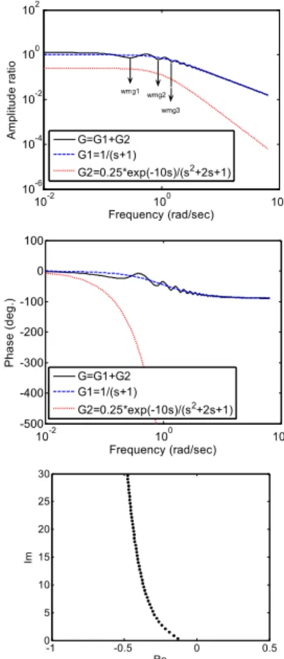
In figures 2 through 5, various frequency responses of a simple QRDS model are shown. The zeros are also drawn to demonstrate the correspondences between the frequency response and the number of model RHP zeros.
10-2 100 102
10-6 10-4 10-2 100 102
Frequency (rad/sec)
A
m
pl
itud
e r
at
io
G=G1+G2 G1=1/(s+1)
G2=0.25*exp(-10s)/(s2+2s+1) wmg1 wmg2
wmg3
10-2 100 102
-500 -400 -300 -200 -100 0 100
Frequency (rad/sec)
Pha
se (
d
eg
.)
G=G1+G2 G1=1/(s+1)
G2=0.25*exp(-10s)/(s2+2s+1)
Re
Im
-1 -0.5 0 0.5 0
5 10 15 20 25 30
Fig. 2 – Frequency response of a QRDS model demonstrating an infinite number of LHP zeros resulting from all frequency gain domination of
delay-free term .
In Fig. 2, all ωmg,i s occur in frequencies where the minimum phase term dominants comparing to the other term. Then, according to the dominant gain concept it is expected that all the zeros are located in LHP. As seen in Fig. 2, this expectation is confirmed by the reality.
10-1 100 101
10-3
10-2 10-1 100
101
Frequncy (rad/sec)
A
m
pl
itude
r
a
tio
G1=0.25/(s2+2s+1)
G2=exp(-5s)/(s+1) G=G1+G2
10-2 10-1 100 101 -300
-250 -200 -150 -100 -50 0
Frequency (rad/sec)
Ph
as
e
(
d
eg
.)
G1=0.25/(s2+2s+1)
Re
Im
-1 -0.5 0 0.5 1 0
5 10 15 20 25 30
Fig. 3 – Frequency response of a QRDS model demonstrating an infinite number of RHP zeros resulting from all frequency gain domination of delay
included term.
In Fig. 3, all the ωmg,is occur in locations where the non-minimum phase term dominants. Then, according to equation (3), it is expected that all the zeros are located in RHP. Fig. 3, confirms this expectation.
10-1 100 101 10-3
10-2 10-1 100
101
Frequency (rad/sec)
A
m
p
lit
ud
e r
a
tio
G1=1/(s+1)2
G2=0.25exp(-5s)/(s+1) G=G1+G2
10-1 100 101
-500 -400 -300 -200 -100 0
Frequency (rad/sec)
P
hase (
de
g.)
G1=1/(s+1)2 G2=0.25exp(-5s)/(s+1) G=G1+G2
Re
Im
-1 -0.5 0 0.5 1 0
5 10 15 20 25 30
Fig. 4 – Frequency response of a QRDS model demonstrating an infinite number of RHP zeros resulting from high frequency gain domination of delay included term and a few number of LHP zeros resulting from low
frequency gain domination of delay free term.
In Fig.4, the minimum phase term dominants in
sec / 4rad < < ∞
− ω . In this interval, 3ωmg,is are located in this frequency range and reminders of ωmg,i s occur in frequencies where the non-minimum phase term is dominant. Then, it is expected that there are 3 LHP zeros and the reminders of zeros are located in RHP. Fig. 4 confirms this expectation.
10-1 100 101
10-3 10-2 10-1 100 101
Frequency (rad/sec)
A
m
plitu
de
r
at
io
G1(s)=0.25/(s+1) G=G1+G2 G2=exp(-5s)/(s+1)2
10-1 100 101
-1500 -1000 -500 0
Frequency (rad/sec)
P
hase
(
deg.
)
G1=0.25/(s+1) G2=exp(-5s)/(s+1)2
G=G1+G2
Re
Im
-1 -0.5 0 0.5 1
0 5 10 15 20 25 30
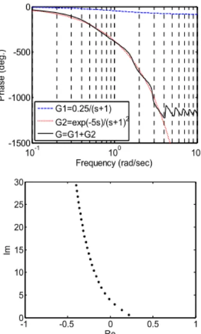
Fig.5 – Frequency response of a QRDS model demonstrating an infinite number of LHP zeros resulting from low frequency gain domination of delay-free term and a few number of RHP zeros resulting from high
frequency gain domination of delay free term.
In Fig.5, contrary to the case of Fig. 4, the non-minimum phase term dominants in −∞<ω<4rad/sec . In this interval, 3ωmg,is and the reminders of
ω
mg,is occur in locations where the minimum phase term dominants. Then, it is expected that there are 3 RHP zeros and the reminders of zeros are located in LHP. Fig. 5, also, confirms this expectation.In control systems, the minimum phase behavior (Fig. 2) is much desirable. The most important point is that, if in an open loop with a QRDS structure, a delay-free term is a first order transfer function, by applying a Dominant Gain Constraint (DGC) on the open loop, the control system will become absolutely stable, in spite of the existence of time-delay or any high order dynamics in the process.
Based on the above viewpoints, stability of the proposed method is proved in the following proposition.
Proposition 1: in a simple open loop transfer function as
std
sol s G s G s e
G ( )= ( )+ ( ) −
2
1 in which G1(s) and G2(s) do
not have any right-half plane poles, if a stable transfer function with an order of 1 or zero, such as Gmb(s), is added
in a way that:
) ( )
( mg,i sol mg,i
mb j G j
G ω ≥ ω
(6)
the control loop will be absolutely stable.
As an explanation, assuming the above-mentioned conditions, the overall open loop transfer function will be
) ( ) ( )
(s G s G s
Gool = mb + sol . If the dominant gain constraint
(eq.6) prevails so that the overall open loop behavior completely traces the Gmb(s) behavior and becomes a minimum phase function, then there will not be any RHP zero in the open loop.
III. COMPARING THE PROPOSED METHOD WITH A GENERALIZED SMITH PREDICTOR
As mentioned before, in [18-20], a method was presented to compensate for the time-delay. This method is based on Smith predictor and because it is capable of controlling QRDS, it is called Generalized Smith Predictor. The control structure of this method is shown in Fig. 6.
Fig.6- Generalized Smith Predictor
In this method, inspired from Smith method for compensating for the time-delay effects, the QRDS model is divided into two parts; Gp+(s), part of the model which includes RHP zeros, and Gp−(s), part of the model which does not have RHP zeros. By compensating for the effects of
) (s Gp
+ from the open loop transfer function, the open loop behavior will be changed from non-minimum phase to minimum phase. If there is no model mismatch, the open loop in this method will become:
) ( )
(s G s
G loop open
GSP = c p−
(7)
Then, all the RHP zeros will be removed from the open loop, however, in the open loop, there are LHP zeros yet. For this system, the characteristic equation will be:
0 ) ( ) (
1+G s G− s =
p
c (8)
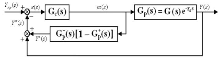
The proposed method in [31] is based on transferring the RHP zeros of open loop transfer function to the LHP using the DGC requirement, instead of requiring a perfect model of the process for eliminating the time-delay from the characteristic equation. The proposed control structure is shown in Fig.7.
Fig.7.The proposed control structure
In this scheme, Gmb(s) is the Dominant Gain Delay Compensator (DGDC), which will be selected in a way that its gain becomes dominant in comparison to the gain of the simple open loop transfer function of, Gsol(s)=Gc(s)Gf(s)Gp(s)Gm(s). In this way, all the RHP zeros resulting from the time-delay will be converted to LHP zeros. We may also call the Gmb(s)
as "Model Bypass Phase Limiter" (MBPL) compensator, due to the fact that it bypasses all the high order as well as the RHP zeros’ dynamics in the loop and limits the phase of open loop function. Thus, by using this compensator, the frequency response behavior of the open loop transfer function will change from delay behavior to non-delay behavior.
The closed loop transfer functions of this system will become:
) ( ) ( ) ( ) ( ) ( 1
) ( ) ( ) ( )
( ) (
s G s G s G s G s G
s G s G s G s
Y s Y
m p f c b m
p f c p
s + +
= (9)
) ( ) ( ) ( ) ( ) ( 1
) ( ) ( ) ( )
( ) (
s G s G s G s G s G
s G s G s G s
d s Y
m p f c mb
d mb d
+ +
+
= (10)
The characteristic equation is:
0 ) ( ) ( ) ( ) ( ) (
1+Gmb s +Gc s Gf s Gp s Gm s = (11) The MBPL function "Gmb(s)" should be selected as a
minimum phase function. Its addition to the open loop by considering the DGC requirement (equation (6)) results in the conversion of all the RHP zeros in the open loop function to the LHP zeros.
IV. COMPARING THE PROPOSED METHOD WITH A PID CONTROLLER
Because of the existence of derivative mode, PID controllers are known to have predictive properties. But, tuning the controller parameters is complex due to the controllers’ high number of parameters. Thus, in order to limit the complexity of PID controllers, some parameters were fixed at a typical value, as recommended in the conventional textbooks on the process control.
On the other hand, since in process control applications, more than 93% of the controllers are of PID type [27], some of the researchers [28, 29] have tried to transfer Smith predictor performance to an ordinary feedback control loop. To achieve this goal, a combination of the controller and predictor must be approximated as a controller. For example, if the original one is a PI controller, a combination of the controller and predictor is usually approximated as a PID controller. In these methods, PID parameters are identified or approximated using PI controller and predictor parameters. However in the proposed method it is easily converted into an ordinary feedback control loop without any need for approximation or identification. In the proposed method, if the controller is a PI controller and it is combined withGmb(s),
a PID controller is gained and, by so doing, according to Fig. 8 and equation (12), the proposed control loop is converted to a conventional feedback control loop. Therefore, PID controller parameters are easily found using simple mathematical correlations.
] 1 [ 1 1 ) ( 1 ) ( + + ′ + ′ = = + + + = + s s s K G s Ks K s G s G f D i c c mb i c mb c PID PI ττ τ τ (12)
V. CHOOSING THE ORDER AND GAIN OF Gmb(s)
In propositions 2 and 3, methods for selecting the order and gain of Gmb(s)are presented.
Proposition 2: in the proposed method, if
G
sol(
s
)
is strictlyproper, the most proper order for
G
mb(
s
)
is first order and if)
(
s
G
sol is proper, the most proper order forG
mb(
s
)
is zero order.Proof: in the proposed method, the overall open loop transfer
function of
G
ool(
s
)
is:s t no sol mo sol sol nb mb mb sol mb ool d e s D s N K s D K s G s G s G − + = + = ) ( ) ( ) ( ) ( ) ( ) ( ) ( ) ( ) ( (13)
where, the subscripts “sol” and “ool” refer to the simple open loop (without MBPL-compensator) and overall open loop, respectively.
K
mb andK
sol are static gains of the compensator and simple open loop transfer function, respectively. Also, "nb
", "mo
" and "no
" are the orders of polynomialsD
mb(
s
)
,N
sol(
s
)
andD
sol(
s
)
, respectively. Then the characteristic equation will become:0 ) ( ) ( ( ) ( ) )
( + nb −std =
mb mo sol sol no sol
mbD s K N s D e
K (14)
According to [32], the required condition for eliminating the RHP zeros from the quasi-polynomial, like the one in (12), is: ⎩ ⎨ ⎧ ≥ − ≤ ⇒ ⎭ ⎬ ⎫ ⎩ ⎨ ⎧ ≥ + ≥ sol mb sol
mb K K
mo no nb K K nb mo
no (15)
The first inequality in (15) corresponds to the high frequency gain domination requirement while the second one satisfies the low frequency gain domination requirement. In the mid-frequency ranges, the gain domination requirement can be obtained by changing the second inequality in (15) to:
sol mb
mb K K
K +Δ > (16) mb
K
Δ is the excessive gain requirement of the compensator to guarantee that there is not any remaining RHP zeros in the overall open loop transfer function. Now, the pertinent argument is this: without satisfying the gain domination at high frequencies, it is impossible to eliminate all the RHP zeros from the open loop transfer function while the low frequency and mid frequency RHP zeros are possible to be eliminated perfectly by adjusting the compensator gain of Kmb. Therefore, there should be a focus on the order of
) (s
Gmb and Gsol(s) with respect to each other in order to
reach to a suitable order for the compensator. Thus, if Gsol(s)
is a proper transfer function, i.e., no=mo, then
nb
=
0
;and if Gsol(s) is a strictly proper transfer function, i.e.
mo
no
>
, then nb≥1. In the last case, the less value, i.e.1
=
nb
, is more desirable. This is due to the fact that, with a first order dominant gain compensator, "Gmb(s)", the control system reaches an absolutely stable condition.Definition 2: The absolute stability in a simple feedback
control loop refers to the situation in which the open loop is a stable delay-free first order transfer function. However, by applying the DGC requirement, one can impose the absolutely stable condition when the process is high order or includes time-delay.
Proposition 3: The best value for Gmb(jω)is the minimum
value which satisfies the DGC condition, i.e. equation (6) for the upper bound of Gsol(j
ω
)uncertainty.Proof: Minimum value which satisfies equation (6) is:
) ( )
( mg,i sol mg,i
mb j G j
G ω = ω (17) Sensitivity functions for the proposed method are obtained as equations (18) and (19):
) ( 1 ) ( ) ( 1 1 ) ( s G s G s G s S mb c p + +
= (18)
) ( ) ( ) ( 1 ) ( ) ( ) ( s G s G s G s G s G s T c p mb c p + +
= (19)
As seen in the above functions, to whatever level the
) (s
Gmb value is increased, S(s) increases and T(s) decreases. Then, the performance will be robust and sluggish by increasing the Gmb(s) value.
Therefore, for the proper performance, equation (6) must be satisfied for the impossible minimum value of Gmb(s). Also, to confirm that there is not any RHP zeros in open loop, (17) must be satisfied for the upper bound of
) (jω
Gsol uncertainty.
VI. SIMULATION
In [31] several examples of the applications of the proposed method was presented for the processes with model mismatches, variable time delay, integral and QRDS models. In this paper the method is used for compensating time delay systems with RHP zeros simultaneously to show the widest applicability of the method. In this section, an example is presented for this case.
Example: Assume a process model such as
2 -4s
p (s 1)
0.1)e -(2s ) s ( G +
= . For applying the proposed method, at
first, the compensator must be selected. The way the Gmb(s)
parameters are chosen is described as the follows:
A. Choosing the order, gain and time constant of Gmb(s) Since, Gp(s) is a strictly proper transfer function,
) (s
Gmb is selected as the first order transfer function. In the
constant are effective parameters. For simplicity in tuning the parameters of Gmb(s) time constant is selected as equal to one and Gmb(s)gain is obtained so that equation (15) is satisfied for the upper bound of Gsol(jω)model uncertainty.
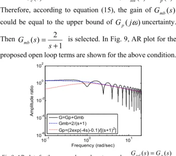
BecauseGc(s)is not determined at first, Gsol(s)=Gp(s).
Therefore, according to equation (15), the gain of Gmb(s)
could be equal to the upper bound of Gp(j
ω
)uncertainty.Then
1 2 ) (
+ =
s s
Gmb is selected. In Fig. 9, AR plot for the
proposed open loop terms are shown for the above condition.
10-1 100 101 10-6
10-4 10-2 100 102
Frequency (rad/sec)
A
m
pl
itude r
ati
o
G=Gp+Gmb Gmb=2/(s+1)
Gp=(2exp(-4s)-0.1)/[(s+1)2]
Fig.9. AR plots for the proposed open loop terms when Gsol(s)=Gp(s) B. Tuning the controller parameters
Now, based on the selected
G
mb(
s
)
, the controller parameters are easily determined by using any kind of tuning procedures. Then, according to the ISE criteria, the controllers are obtained ass 6658 . 0 2437 . 1 ) s (
Gcp =− − and
s 2122 . 0 8987 . 0 ) s (
Gcf =− − for the proposed and ordinary feedback methods respectively.
C. Retuning of the compensator gain to remove all the
RHP zeros from the Gool(s)=Gmb(s)+Gp(s)Gc(s)
Because in this condition, in a specific range, Gool(s)is the non-minimum phase, the gain of Gmb(s) should be increased. The minimum value of the Gmb(s)gain which results in the Gool(s)’s becoming minimum phase is 2.5. Then, the compensator is selected as
1 5 . 2 ) (
+ =
s s
Gmb . In Fig.
10, AR plot for the proposed open loop terms are shown for the above condition.
10-2 100
10-4 10-2 100 102
Frequency (rad/sec)
A
m
p
lit
ude r
at
io
G=Gmb+G1 Gmb=2.5/(s+1) G1=Gp*Gcp
Fig.10. AR plots for the proposed open loop terms
In Fig. 11, the proposed and feedback method responses are shown. It should be noted that a load disturbance equal to
5 . 0
− was inputted in the control system at time 150 sec.
Fig. 11.The proposed and feedback methods’ responses
In Table 1, two responses which were mentioned in Fig. 9 are compared.
TABLE1-IAE AND ISE FOR THE PROPOSED AND FEEDBACK METHODS
RESPONSES IN FIG.9
Undershoot ISE
IAE Method
-0.54 57
60.2 Proposed
-0.8 68.5
68.8 Ordinary
Feedback
As can be seen in this table, the proposed method response has the lower oscillation and lower undershoots.
VII. CONCLUSIONS
In this paper, the proposed method in [31] is studied from a new point of view. In this viewpoint, time delay is considered as infinite RHP zeros and it is shown that how the minimum phase and non-minimum phase behaviors of an irrational transfer function could relate to the location of zeros in the RHP or LHP. Considering that in the proposed method, open loop frequency response was used for determining Gmb(s)
parameters, this method does not need an exact model, which is an advantage for the proposed method with respect to the delay prediction methods (i.e., Smith predictor, Generalized Smith predictor and DTcs). Also, when the proposed method is compared with a PID controller, the tuning complexity of a PID controller is not observed, which is because, in the proposed method, derivative mode parameters were determined using a dominant gain constraint.
REFERENCES
[1] T. Hägglund, “A predictive PI Controller for Processes with Long Dead-Times, ” IEEE Contr. Syst. Mag., vol. 12, pp. 57 – 60, 1992. [2] O. J. M. Smith, “A controller to overcome dead time, ” ISA Journal, vol.
6, pp.28-33, 1959.
[3] J. P. Richard, “ Time-delay systems: an overview of some recent advances and open problems”, Automatica , vol. 39, pp.1667-1694, 2003.
[4] J.E.Normey-Rico & E. F. Camacho, “Dead-time compensators: A survey, ” Control Engineering Practice, vol.16, pp. 407-428, 2008. [5] Z. Palmor, “Stability Properties of Smith Dead-Time Compensator
Controllers, ” Int.J. Control, vol. 32, pp. 937-949, 1980.
[6] J.E. Normey-Rico, C. Bordons, & E. F. Camacho, “Improving the robustness of Dead-time compansating PI controllers, ” Control Engineering Practice, vol. 5, pp. 801-810, 1997.
[7] A. Ingimundarson & T. Hägglund, “Robust tuning procedure of Dead-time compensating controllers,” Control Engineering Practice,vol. 9, pp. 1195-1208, 2001.
[8] W. Michiels, & S.i. Niculescu,“On the delay sensitivity of Smith predictors,”International Journal of Systems Science, vol. 34, pp.543-552, 2003.
[10] K. Astrom, C. C. Hang, & B. C. Lim, “A New Smith Predictor for Controlling a Process with an Integrator and Long Dead-Time, ” IEEE Transactions on Automatic Control, vol. 39, pp. 343-345, 1994. [11] Lu., Xiang , Y., Yang, Q. Wang, and W. Zheng, “A Double Two -
Degree - of -Freedom Control Scheme for Improved Control of Unstable Delay Processes, ” Journal of Process Control, vol. 15, pp. 605 – 614, 2005.
[12] I. Kaya, and D. P. Atherton, “A new PI - PD Smith Predictor for Control of Processes with Long Dead-Time, ” in: 14th IFAC World Congress 1999, Vol. C: 283-288.
[13] I. Kaya, “Obtaining Controller Parameters for a New PI-PD Smith Predictor Using Auto tuning, ” Journal of Process Control, vol. 13, pp.465-472, 2003.
[14] S. Majhi, and D. P. Atherton. “Modified Smith Predictor and Controller for Processes with Time-Delay, ” IEE Proc. Control Theory Appl. , vol. 146, pp. 359-366, 1999.
[15] S. Majhi, and D. P. Atherton. “Obtaining Controller Parameters for a New Smith Predictor Using Auto Tuning, ” Automatica, vol. 36, pp. 1651-1658, 2000.
[16] M. R. Mataušek, and A. D. Micić. “A modified Smith Predictor for Controlling a Process with an Integrator and Long Dead-Time, ” IEEE Trans. Automat. Control, vol. 41, pp.1196-1203, 1996.
[17] M . R Mataušek, and A. D. Micić. “On the Modified Smith Predictor for Controlling a Process with an Integrator and Long Dead-Time, ”
IEEE Trans. Automat. Cont., vol. 44, pp. 1603-1606, 1999.
[18] S. Ramanathan, R. L. Curl And C. Kravaris. “Dynamics and control of the cumulative mass fraction of a particle size distribution, ” ACC Proc. 1987, Minneapolis.
[19] S. Ramanathan, Control of Quasirational Distributed Systems with Examples on the Control of Cumulative Mass Fraction of Particle Size Distribution. Ph.D. Thesis, University of Michigan, Ann Arbor, 1988. [20] S. Ramanathan, R. L. Curl and C. Kravaris. “Dynamics and Control of
Quasirational Systems, ” AIChE J. 1989; 35(6): 1017-1028. [21] U. Vollmer, J. Raisch, “H∞-Control of a continuous crystallizer, ”
Control Engineering Practice , vol. 9, pp. 837-845, 2001.
[22] U. Vollmer, J. Raisch “Population balance modeling and H∞-Controller design for a crystallization process, ” Chemical Engineering Science, vol. 57, pp. 4401-4414, 2002 .
[23] P. Zĺtek, J. Hlava, “Anisochronic internal model control of time-delay systems, ” Control Engineering Practice, vol. 9, pp.501-516, 2001. [24] K.J. Astrom, and T. Hagglund, “The future of PID control, ” Control
Engineering Practice, vol. 9, pp. 1163-1175, 2001.
[25] A. Ingimundarson, & T. Hägglund, “Performance comparison between PID and Dead-time compensating controllers, ” Journal of Process Control, vol. 12, pp. 887-895, 2002.
[26] Aidan O'Dwyer. Handbook of PI and PID controllers tuning rules. Imperial Collage Press, 2nd edition, 2006.
[27] K.J. Astrom, and T. Hagglund, in The Control Handbook, Editor W.S. Levine,(CRC/IEEE Press), pp. 198-209, 1996.
[28] S. Glickman, R. Kulessky, and G. Nudelman, “PID control design for power station processes based on time—Delay compensation—Smith predictor,” in MMAR 2002 IEEE Conf., Poland, pp. 1163–1168. [29] Tsai, K.I., W. Fu-Jen, L. Hao-Chuan and C. Hsu-Cheng, “A novel
control scheme for temperature control of machine tool coolers, ” J. Applied Sci., vol. 8, pp. 2491-2495, 2008.
[30] M. Shirvani, M. Esmaeli., “Exploiting distributed parameter process systems behaviors in frequency domain, ” 18th international congress of chemical and process engineering, Chisa., Prauge, 2008.
[31] M. Shirvani, M. Esmaeli., “A New method for time-delay compensation in control systems”, Iranian J. of Chemistry & Chemical Engineering, vol. 27, no. 4, 2008.
[32] R. E. Bellman, and K. L. Cooke. Differential-Difference Equations. Academic Press, New York,1963.
M. Esmaeli, photograph and biography not available at the time of publishing.