Beach Wheelchair Project
June 14, 2013
for Bridge II Sports
Team SandCrawler
Rory Aronson - [email protected]
Joshua Marcum - [email protected]
Sam Coyne - [email protected]
Alex Hayes - [email protected]
Alexa Colburn - [email protected]
Max Hessel - [email protected]
Benedikt Strauss - [email protected]
Marvin Rimmele - [email protected]
Marco Pietsch - [email protected]
College of Engineering
California Polytechnic State University, San Luis Obispo Munich University of Applied Sciences
Statement of Disclaimer
Table of Contents
Statement of Disclaimer Table of Contents Table of Figures Table of Tables
1 - Executive Summary 2 - Introduction
Design Challenge Background Research
Manual Beach Wheelchair Notes Electric Beach Wheelchair Notes Objectives Customer Requirements Optional Features Design Development Management Plan Timetable Gantt Chart
3 - Conceptual Models Prototyping Lab 3 Wheeled Design Using Bike Wheels
Using Hand Truck Wheels Scissor Lift
Sliding Rear Assembly Internal Gear Hub Lever Drive
4 - Subsystem Pugh Matrices Collapsing and Disassembling Drive Systems
Number and Size of Wheels Seat Adjustability
Seat Raising Mechanism Gear Shifting
Tire Selection Floating
Water Propulsion 5 - Initial Whole Concepts
Avila Wheelchair Designs
Alex Hayes’s Initial Whole Concept Rory Aronson’s Initial Whole Concept Marco Pietsch’s Initial Whole Concept Marvin Rimmele’s Initial Whole Concept Max Hessel’s Initial Whole Concept Initial Whole Concept Matrix
6 - Iterated Whole Concepts
Rory Aronson’s Iterated Whole Concept Marco Pietsch’s Iterated Whole Concept Final Selection Process
7 - The Final Concept
Satisfying User Requirements Safety Considerations Gas Piston Frame Cranks Belts Hand Brake
Headrest and Footrests Balloon Tires
8 - The Final Design Frame Construction Wheels Seat Construction Lower frame Upper frame
Backrest Adjusting Mechanism Torsion spring system
Linkages & bushing Textile meshing Safety
Calculations
Bolt Calculations
Linkages bushings calculation
Backrest adjusting mechanism - piston calculation Piston Hand Crank Components Construction Rear Pulley Construction
Brake Construction Maintenance Cost Estimation Testing Plan Weight Capacity Floatability
Speed and Ease of Maneuverability Size
Disassembly Piston Stability
Feedback from Potential Users 9 - Manufacturing
Overview
Main Frame Construction Cutting Materials Jigging Finishing Mini-frame Construction Cutting Materials Jigging Finish Work
Push Handle Construction Rear Drive Hub Construction
Cutting Materials Machining Round 1 Welding
Machining Round 2 Tensioner Construction
Cutting Materials Machining Welding Finishing
Pin Disk Construction Crank Construction Axle Construction
Rear Wheel Modification Final Assembly
Seat Manufacturing 10 - Testing
Crank Realignment
Arm Maneuverability and Spacing
Hand Force Requirements and Ramp Test Drivability in Different Conditions
Floatation Stability Safety Braking Maintenance Engineering Specifications Client Testing
11 - Implemented and Proposed Design Changes Frame Wheels Belt Guard Crank Assembly Footrest Assembly Drive System Seat Brake Steerability 12 - Closing Remarks 13 - Appendices
Appendix 1: Existing Beach Wheelchair Designs Appendix 2: Engineering Specifications List Appendix 3: Gantt Chart
Appendix 4: Bill of Materials Appendix 5: Detailed Drawings
Main Frame Crank Assembly Rear Hub Assembly Front Wheel Assembly Main Frame
Front Wheel Frames Tensioner* Pin Disk Crank Arm Drive Hub Axle Push Handles Rear Drive Rod
Appendix 6: Supporting Analysis
Forces During Wheelchair and Hand cycle Use Wheelchair Force Testing
Supporting Calculations for Load Analysis on Lower Member of Frame Seat Module Calculations
Supporting Calculations for Forces on Crank arm Supporting Calculations for Force on Crankshaft Appendix 7: Team Contract
Team Sandspitter Contract
Member Roles and Responsibilities Commitment and Accountability Communication Pathways Conflict Resolution
Project Room Civility
Appendix 8: Anodization Forms Appendix 9: Instruction Manual Parts List
1 - Seatbelt
Table of Figures
Figure Number
Title Page
1.1 The Cal Poly Wheelchair 15
1.2 The Munich Wheelchair 15
2.1 The Natural Access Landeez™ manual beach wheelchair in Avila Beach
17
2.2 Electric beach wheelchair in Avila Beach 18
2.3 Method of approach in order of timeline, with iteration illustrated as backward lines
20
2.4 Project Gantt chart showing dependencies 22
3.1 Lego™ model 23
3.2 Floating Model 23
3.3 Wheel adjusting model 23
3.4 Tank tread model 23
3.5 Shock absorbing model 24
3.6 Hand crank model 24
3.7 The 3 wheeled conceptual model proved to be unstable 24 3.8 The 3 wheeled design with mountain bike tires proved to dig into the
sand
25
3.9 Go-kart tires sinking into the sand 26
3.10 Modified go-kart tires to have an increased and flatter contact surface 26 3.11 Scissor lift conceptual model made of a wooden camping chair 27 3.12 Sliding rear assembly concept in the raised position 27 3.13 Sliding rear assembly concept in the lowered position 27 3.14 Internal gear hub conceptual model using bicycle parts 28
3.15 Internal gear hub conceptual model close up 28
3.17 Close up on lever drive conceptual model 29
5.1 Joshua’s initial whole concept 43
5.2 Sam’s initial whole concept 44
5.3 Bene’s initial whole concept 45
5.4 Bene’s initial whole concept 45
5.5 Bene’s initial whole concept 45
5.6 Alex’s initial whole concept 46
5.7 Exploded view of Alex’s concept 47
5.8 Side profile of concept showing the raising and lowering aspects 47
5.9 Rory’s initial whole concept 49
5.10 Marco’s individual whole concept 50
5.11 Marvin’s initial whole concept 50
5.12 Max’s initial whole concept 51
6.1 Rory’s iterated whole concept 55
6.2 Marco’s iterated whole concept 56
7.1 Final concept design sketch 58
7.2 CAD render of the final concept design in the driving position 58 7.3 CAD render of the final concept design in the transfer position 59 7.4 CAD render of the final concept design in the floating and sand exit
position
59
7.5 Gas piston sketches and rubber shielding 61
7.6 Piston lever system 62
7.7 Calculation of piston force based on geometry and user weight (Fy) 63 7.8 Detailed drawing of the frame. Member location and sizing subject to
change
63
7.9 Close up sketch of the handle, ratchet, crank, and pulley assembly 64
7.12 Close up of the hand brake mechanism 66
7.13 49cm diameter balloon tire from Wheeleez.com 66
8.0 The SandCrawler 68
8.1 Final frame design. Made of square and cylindrical aluminum tubing 70
8.2 Actual footrest being bought 71
8.3 Close up conceptual CAD of footrests 71
8.4 Rear wheel with modifications to hub 72
8.5 Front wheel assembly 73
8.6 Lower frame cross section 74
8.7 Lower frame and the links for the upper frame 75
8.8 Backrest Adjustment Mechanism 76
8.9 Torsion Spring 77
8.10 Linkages & bushing in exploded view 78
8.11 Textile meshing wrapped around the circular tubes 79 8.12 Piston Assembly along with hydraulic line and push button 81
8.13 Exploded view of the hand crank 82
8.14 Free Body Diagram of shaft with Adjustable Lengths 83
8.15 Force and Moment Relations 83
8.16 Diagram illustrating the shear and bending forces on the pin 84
8.17 Bending and shear relations used 84
8.18 Relations used to determine bearing stress load on pin disk 85
8.19 Exploded view of the rear pulley assembly 87
8.20 Force testing at Avila Beach 88
8.21 Brake assembly 89
9.1 Cutting square tubing with the horizontal band saw 93 9.2 Cutting square tubing with the horizontal band saw 93
9.4 Second mainframe jig 94 9.5 Torsion spring resting on Frankenstein nubs for positioning and cutting
length
94
9.6 Drilling the first holes in the frame using the mill 95
9.7 Miniframe Jig 1 96
9.8 Miniframe Jig 2 96
9.9 Caster mounting plate offset block 97
9.10 Prepared for welding push handle stock 98
9.11 Rear Drive Hub holes being machined with the rotary table 99
9.12 Rear Drive Hubs and a mill boring bar 99
9.13 Milling the circular grooves 100
9.14 Contact between the axle and plate 100
9.15 Final design of the brake/tensioner system 101
9.16 Pin Disk under construction with the drill press 101
9.17 Gates sprocket being mounted to pin disk. 101
9.18 Crank manufacturing in progress 102
9.19 Rear hub disassembled and ready to be drilled 103
9.20 The ‘merican way of squaring the seat 103
9.21 Perfect weld root 104
9.22 Tempering oven 105
9.23 Tungsten inert gas welding 105
10.1 The disassembled wheelchair in the back of a Subaru hatchback 107 10.2 Navigating the wheelchair ramp corner at Avila Beach 108 10.3 Sam operating the wheelchair on a 1:10 slope ramp 109 10.4 Operating the wheelchair on hard packed and wet sand 110 10.5 Operating the wheelchair in shallow water conditions 110
10.7 Brake test at Avila 112 10.8 Rinsing off the wheelchair components with the beach shower 113
10.9 Robert approaching the sand at Avila 117
10.10 Robert in shallow water, enjoying himself 117
10.11 Robert and Cindy having fun on the beach. 118
10.12 Josh helping out Robert avoid some holes in the soft sand 118 10.13 Robert heading down the standard wheelchair ramp 119
10.14 Robert engaging the thumb screw on the cranks 119
11.1 Application of shaft collars on the crank assemblies 121 11.2 Spacer block on the mini frames to provide adequate clearance for the
casters
122
11.3 Modified footrest posts 122
11.4 Gates belt drive misalignment 123
11.5 Application of shaft collars on the rear axle tube 123
11.6 Plastic sheet replacing the seat mesh material 124
11.7 Handles to fold the backrest down are difficult to use 125
Table of Tables
Table Number
Description Page(s)
4.1 Collapsing and Disassembling Pugh Matrix for Folding Mechanism 31 4.2 Drive systems decision matrix for Belt Lever and Hand Crank Drive 32 4.3 Number and Size of Wheels Decision Matrix for 2 Big Wheels and 2
Small Front
33
4.4 Seat adjustability decision matrix final scores. 35
4.5 Seat raising mechanism Pugh matrix final scores 36
4.6 Drivetrain parameters and engineering targets 36
4.7 Drivetrain decision matrix results 37
4.8 Gear shifting subsystem matrix and final results. 37
4.9 Tire selection Pugh matrix results 38-39
4.1 Floating subsystem matrix and final results. 40
4.11 Water propulsion subsystem matrix and final results 41 5.1 Initial whole concept matrix criteria and weighting 52-53
5.2 Results of the matrix 54
7.1 Costs of balloon wheels from Wheeleez.com 67
8.1 Cost estimation 90
9.1 Estimated number of man hours for the manufacturing and assembly of components
92
10.1 Weights of each component 108
10.2 Scale 1-10, higher scores mean easier operation 110
1 - Executive Summary
Bridge II Sports, a North Carolina based nonprofit organization that provides opportunities for children and adults who are physically challenged to play team and individual sports wanted a wheelchair to allow their participants to independently access and enjoy the full beach experience. Bridge II Sports presented the project to the Cal Poly Interdisciplinary Senior Project class in the Fall of 2012. Four Cal Poly Engineering students, one Cal Poly Kinesiology student, and four Engineering students from the Munich University of Applied Sciences jumped on board.
The design that the team implemented is the product of research into existing designs, many prototypes, and manufacturing efforts from around the globe. The four main features of the chair are as follows:
1. Balloon tires are used to allow easy travel across the sand and also provide adequate stability and buoyancy for complete entrance into the water.
2. The seat can raise and lower for easy access to the sand, increased stability in water, and ease of transfer from the user’s everyday wheelchair.
3. Hand cranks allow the user to independently operate the wheelchair.
4. The wheelchair disassembles into eight components without the use of tools to be fit into a sedan or hatchback vehicle.
The following report details the design, build, test, and report process that the team underwent to create the two functioning beach wheelchairs seen below by Spring of 2013.
2 - Introduction
Design Challenge
Numerous beach wheelchairs exist today that provide people with disabilities the ability to access the beach and enjoy oceans and lakes. This project’s goal is to design and build a new beach wheelchair or device that will allow people with physical disabilities to move across a sandy beach and go in the water with more ease and independence than before.
The client, Bridge II Sports of North Carolina, is an organization that enhances the lives of people with physical disabilities through sport and physical activity. A group of four Cal Poly Engineering students, a Cal Poly Kinesiology student, and four Munich University of Applied Sciences Engineering students are designing this device for Bridge II Sports.
Currently there are a number of beach wheelchairs that exist but none that satisfy the needs of the customer. For example, some wheelchairs do not allow the user to move independently, while others are electric and do not provide the physical exercise desired by the customer. Many wheelchairs do not allow the user to float in the water and very few beach wheelchairs are collapsible enough to allow the user to independently put the wheelchair into their car.
The device’s design will take into consideration the user requirements set forth by the client as well as features the design team has learned through research and testing of existing designs. These requirements have been converted into an engineering specification list and are what will be used to gauge the project’s success upon delivery to the sponsor. The main requirements as presented by the customer are:
● Allow the user to experience the full beach experience ○ Allow the user to enter the water
○ Allow the user to reach the sand
○ Allow the user to move easily around the beach ● Provide exercise for the user
● Be transportable in the user’s car and require no assistance in loading
Background Research
Manual Beach Wheelchair Notes
● Adjustable armrests allowed getting in and out of the chair easier. ● The leg rests can fold all the way up for storage.
● Hand brake (behind seat) is very hard to engage from the seated position.
● The balloon tires from Wheeleez™ function well but pick up sticky sand very easily. ● When taken in the water, the side-to-side stability is OK while front to back stability is
unmanageable, causing the user to tip over in water.
● Once in the water and the wheels lift off the ground, you lose the ability to move around. ● In sticky or soft sand, pushing the chair became fatiguing quickly. Hard packed sand was
enjoyable to push over.
● Push rims on the wheels did not exist but would have helped because the large, sandy tires are hard to grip.
Figure 2.1: The Natural Access Landeez™ manual beach wheelchair in Avila Beach.
Electric Beach Wheelchair Notes
● This thing is fast!● Senior citizens can be wary of it due to its power. ● Holds 9 hours of battery charge.
Figure 2.2: Electric beach wheelchair in Avila Beach.
We then searched the Internet for other beach wheelchair designs and noted their features and specifications, analyzed their pictures and watched their videos. Appendix 1 provides a breakdown of these designs and some key notes.
The team found applicable codes for wheelchair design that will need to be met such as fitting through a 32 inch wide standard ADA doorway, and being able to move up slopes as steep as 1:8.
Objectives
As mentioned previously, the main objective for this project is to design a means of transportation for people with disabilities to move across a sandy beach. After meeting with Fiona Allen of Bridge II Sports we developed a list of requirements and optional functions as well. The chair will be checked out by Bridge II Sports participants, placed in their personal car and driven to the beach.
Customer Requirements
● Allow person in wheelchair to travel independently on the beach. ● Allow a person with a disability to get in and out without assistance. ● The device can fit inside a hatchback or minivan trunk.
● The device can go in shallow water at least a few inches. ● Supports a fully-grown adult.
● Constructed to easily lift in and out of the car.
● Fits on a standard wheelchair ramp and through a standard ADA doorway. ● Does not require charging or maintenance for 1 days use.
● Is adaptable for a wide variety of physical disabilities. ● Has leg and arm rests.
Optional Features
● Can fully float in the water.
● Accommodates accessories such as umbrellas or drink holders. ● Have power assistance or gear reductions.
● Have appropriate straps.
Most of the requirements that were generated for this project came from just a couple specific ideas that the customer wanted and the rest of the requirements fell under them. The specific needs that the customer asked for was that it had to give the experience of going to the beach and had to let the user operate the device independently. Because these needs made a lot of room for creativity, a lot of the requirements were made based off research. The requirements that we found from our research was that it needed to have brakes, have adjustable leg and armrests, be able to support an adult, and require little to no maintenance. Some of the requirements that fall under letting the user have the ‘beach experience’ are in the optional section with being able to float and ease of maneuverability. Because being an independent person is so important to people with disabilities, the majority of the requirements fell under this category. Requirements such as fitting into a hatchback or minivan and being lightweight enough for someone with limited lifting abilities to move the device are a part of this category. A few more requirements may be added or taken away from the design based on the early communication with the clients. A list of all the current requirements that we plan on using is in Appendix 2.
Design Development
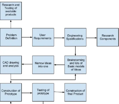
Our team consists of 4 Cal Poly engineering students, a kinesiology student, and 4 Mechanical engineering students from Munich, Germany. All of us are working together to create a finished product. The beginning stages will start with identifying the problem. Researching and testing existing products similar to what we want to design will also play a part in figuring out what designs work, what do not, and what needs improving. The clients are contacted to figure out user requirements. Once we have all the wants and needs of the user, a collaborative effort between everyone in the team will make engineering specifications. Once we have some specifications to work off of, a lot of brainstorming, sketches, and ideas for designs of the wheelchair will be made. Different types of models will be made by all the team members and in a few weeks the number of models will be narrowed down to the most ideal model. During this time, research will be split up for different parts of the possible product so that it satisfies our specifications.
their exams. A full CAD design should be finished by week 5 of winter quarter. From this point, building of the product will commence. After our first prototype has been built, testing will start and adjustments will be made until a final product is done. Figure 3 summarizes our method of approach.
Figure 2.3. Method of approach in order of timeline, with iteration illustrated as backward lines.
Management Plan
The SLO division has defined responsibilities as such: ● Rory
○ Primary Contact with Bridge II Sports. ○ Partnered with Marvin
● Joshua
○ Primary Contact with Munich Division ○ Partnered with Benedikt
● Sam
○ Meeting Scheduler ○ Partnered with Max ● Alex
○ Primary Contact with Kinesiology Division ○ Partnered with Marco
have also split into four sub teams consisting of 1 Cal Poly student and 1 Munich student so as to streamline communication and increase collaboration.
The SLO Division will be meeting at a minimum of once per week on Thursday afternoons to continue project progress. In addition, other meetings will be scheduled by the group as necessary. Specific protocol has been created for group members who do not attend meetings or participate actively in the project as seen in the Team Contract (Appendix 7). SLO Division, through Rory will be contacting Bridge II Sports to provide updates and ask questions as often as necessary, most likely once per two weeks.
SLO Division is estimating that we will each be spending roughly 7-10 hours per week for a total of around 1000 hours spent on this project. In addition we expect that the Munich division will be committing a similar amount of time for a total of 2000 man-hours for the whole project.
Timetable
● Requirements Document - 10/25/2012 ● Conceptual Model - 10/30/2012 ● Conceptual Design Report - 11/27/2012 ● Project Schedule - 11/12/2012 ● Detailed Design Document - 2/7/2012 ● Delivery Date - 6/7/2013
Gantt Chart
3 - Conceptual Models
Prototyping Lab
The first stage of building concept models was to make many “quick and dirty” concepts built out of everyday household materials such as popsicle sticks, hot glue, ping pong balls, cardboard, and Legos™. This exercise took place on October 23, 2012 at Cal Poly and the team built over 10 small prototypes. Figures 3.1 through 3.6 show a few of the ideas that came out of the exercise that were later developed further.
The exercise proved to be fun and exciting (we were finally building things!) but also limiting. The choice of materials was small and the time to build each model lengthy. At some points, it felt like doing a hand sketch would have been far more effective because a more exact shape could have been expressed and it would have happened a lot quicker.
Figure 3.5: Shock absorbing model. Figure 3.6: Hand crank model.
3 Wheeled Design
Sam and Rory constructed a 3 wheeled prototype using 26 inch standard mountain bike wheels (See Figure 3.7). The fabrication consisted of welding the wheel axles directly into the frame of a steel framed patio chair. The design proved to be extremely unstable as the center of mass was very high, the overall footprint of the contact points was small, and the center of mass was located very close to the tipping point action lines between the front wheel and either of the two rear wheels. This conceptual model taught the team through failure that a 3-wheeled design would be unusable if it is not stable enough for the user.
Using Bike Wheels
To examine the use of bicycle wheels and tires on the sand, the SLO team took the 3-wheeled conceptual model to the beach volleyball court located in Meadow Park in San Luis Obispo. The relatively skinny tires dug into the sand quickly and the fact that the load was concentrated on only one wheel in the front only exacerbated the digging. Though these initial results were poor, the team decided that further investigation was still necessary.
The team researched online and found that the bike manufacturer Surly makes large bicycle tires for use on snow and sand. The team watched videos of these tires performing at the beach and used this knowledge in the Tire Selection subsystem Pugh matrix seen later in this report.
Figure 3.8: The 3 wheeled design with mountain bike tires proved to dig into the sand.
Using Hand Truck Wheels
Figure 3.9: Go-kart tires sinking into the sand.
It was noted that even though the tires are wider than standard mountain bike tires, they are very rounded such that they sank into the sand until the contact surface area was sufficient. If the tires had a flatter face like balloon tires, then they would have performed better. Based on this thought, Sam and Rory cut out cardboard and taped it onto the tires to provide more surface area as seen in Figure 3.10. This modification helped significantly, but the tires still proved to have too small of a diameter such that it could not go over large mounds in the sand without digging in.
Figure 3.10: Modified go-kart tires to have an increased and flatter contact surface.
Scissor Lift
rod that is protruding out the front of the chair. Probably the biggest learning experience from this design was that we found out that we needed a more complicated design in order for the seat to lift back to the upright position.
Figure 3.11: Scissor lift conceptual model made of a wooden camping chair.
Sliding Rear Assembly
The sliding rear assembly was the second concept prototype for a seat lowering mechanism. The way that this prototype works is that there is a smaller tube that is attached to the seat that slides inside a bigger tube that is attached to the frame of the wheelchair. The tubes are in a diagonal direction so that you not only get a lower center of gravity but the wheelbase also expands so that there is some added stability. Again, the problem with this design is that it’s very difficult to integrate a system that the user can operate the seat lifting mechanism. The other problem this design taught us was that sand can and corrosion could make a system with telescoping tubes very difficult.
Figure 3.12: Sliding rear assembly concept in the raised position.
Internal Gear Hub
One of the biggest problems with beach wheelchairs currently on the market today is that they are very difficult to traverse across sand without electric power. Because we wanted the user to have some physical exercise and use in the water, electrical power was not considered. One of the ways to help the user with the required power to move across the sand was the internal gear hub. The gear hub that was used in our prototype had three different speeds. The benefits of using the internal gear was that you could integrate a push rim and it is easy to change from high to low gears based on the user’s strength.
The durability of internal gears is a big problem. From experience, many internal gears are able to withstand rain, but when submerged for a long period of time, the gears deteriorate quickly. The other problem was the push rim that was integrated into the system. Problems with the push rim involve the rim digging into the sand and height adjustability of the rim for different users and seat heights.
Figure 3.14: Internal gear hub conceptual model using bicycle parts.
Figure 3.15: Internal gear hub conceptual model close up.
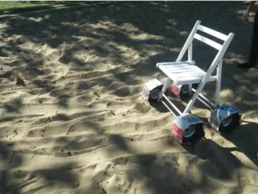
Lever Drive
The beach wheelchair from Avila has very poor mobility when simply pushing the wheels. For this model we tested the feasibility and functionality of a potential lever drive system. To create this model, we took a steel-frame lawn chair and welded two bike forks to the sides. We then welded metal rods to the gear sets of rear bike wheels. Those wheels then fit into the forks on the sides such that the levers were accessible to the user. Shopping cart wheels were welded to the back of the chair.
bidirectional ratchet is needed for the chair to move in reverse. The rear wheels were also fixed in this prototype which made turning difficult.
Despite its drawbacks however, we also found that using the lever system with a direct drive was very easy to operate. The length of the lever arm provided a clear mechanical advantage to the user, making it easy to move the chair even on rough terrain.
4 - Subsystem Pugh Matrices
Collapsing and Disassembling
To make the user as independent as possible it’s important that he is able to store the wheelchair in his car. To provide comfort it has to be big, so there has to be some kind of mechanism to reduce the dimension. For an independent person it’s very important to not need any help to get the wheelchair in and out of his car, which gives us the duty to make our construction as lightweight as possible.
As shown in Appendix 2: Engineering Specification List our wheelchair has to fulfill the geometric requirements to be collapsible (back rest folds 180 degrees) and to fit into a hatchback trunk (max size: 30.25" X 35" X 32"). Under force and torque we considered the weight topic and set the goal for the maximum weight to 35 lbs.
Our main goal was to make it easy to use, so we gave it in our Pugh matrix the highest weight (5). We also considered long durability (4) and lightweight design (4). A point contributing to the Ease of Use is the amount of necessary tools (3), which was important enough for us to treat it as its own criterion. To keep our ideas realistic, we put in the category difficulty to create (2). As it doesn’t have any direct benefit to the user, we gave it the smallest weight.
We had a closer look on four ideas:
● Screws (total weighted rating: -6.57) ● Clips (10.40)
● Spring loaded pins (18.86) ● Folding (21.43)
The screws had despite in the weight column no big positive rating. The idea was to screw parts together and open undo them for moving or disassembly of parts. This would cause a lot of trouble for the user.
Clipping parts together seemed to be a pretty good idea, but failed our expectations concerning durability, especially of the parts that have to be moved or disassembled often. It will still be a good way to attach optional parts like oars to the chair.
Our favorite idea is the folding system; the exact rating is shown in Table 4.1. As easily seen it performed excellent in the ease of use section. As it has no real weak points, it became our clear favorite. It’s an easy technology which offers the user the highest possible comfort.
Wherever we want a part to be moved and not completely disassembled, which use a folding system. When we want a part to be taken away from the frame out of weight reasons we will use spring loaded pins. Those two concepts provide clearly the highest satisfaction for our users and will fulfill our targets.
Table 4.1: Collapsing and Disassembling Pugh Matrix for Folding Mechanism.
Criteria Weight (1-5) Rory Alex Sam Joshua Marco Marvin Max Benedikt
Difficulty To Create 2 1 1 1 1 0 1 0 0 Ease of Use 5 2 2 2 2 2 2 1 1 Durability 4 1 0 0 1 1 0 0 0 Weight 4 2 1 2 1 1 1 1 1 Amount of necessary
tools 3 2 0 2 1 0 0 1 1
Total - 30 16 26 23 18 16 12 9
AVG Total 21.43
Drive Systems
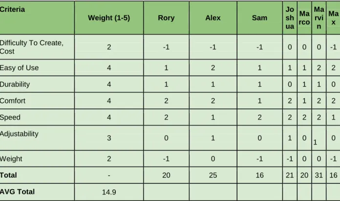
As can be seen in the green column, the ratcheting lever design has the most positive attributes and least negative attributes compared to all the other columns. However, the Toothed Belt Drive system excels in some important areas that the Ratcheting Lever design does not, namely the water and sand endurance criterion. If the ratcheting system were made out of metal, the sand would increase wear on the parts, and seawater could corrode it. Small intricate parts that could be hard to replace would wear the fastest. Whereas the Toothed Belt drive could be used in the water and sand without corroding or having major wear damage.
If the pulleys that will receive the belt are made of plastic also, then the parts will easily function in sand and water with little issue. The plastic chain can be considered for the same reasons as the belt, however it would be a little more complicated to assemble, and more expensive to build. The major advantage to the ratcheting lever over the toothed belt is the ease of assembly.
However, I feel as though the functionality of the system in water and sand is more valuable an attribute than the ease of assembly and lack of lubricants in the ratcheting lever. I feel like a belt drive can be designed to compensate for these drawbacks such as adding a spring tension release lever, and sealed roller bearings. Despite the chart indicating that the lever ratcheting system has the most positive qualities and least negative qualities, I would still choose the toothed belt system.
Table 4.2: Drive systems decision matrix for Belt Lever and Hand Crank Drive.
Criteria
Weight (1-5) Rory Alex Sam
Jo sh ua Ma rco Ma rvi n Ma x
Difficulty To Create,
Cost 2 -1 -1 -1 0 0 0 -1 Easy of Use 4 1 2 1 1 1 2 2 Durability 4 1 1 1 0 1 1 0 Comfort 4 2 2 1 2 1 2 2
Speed 4 2 1 2 2 2 2 1
Adjustability
3 0 1 0 1 0 1 0 Weight 2 -1 0 -1 -1 0 0 -1
Total - 20 25 16 21 20 31 16
AVG Total 14.9
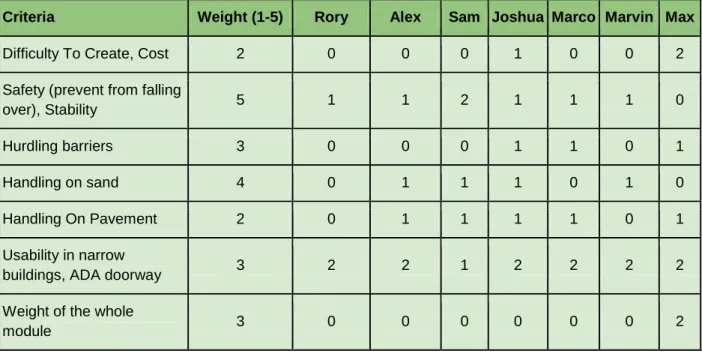
Number and Size of Wheels
In the end, having two larger wheels in the back and two smaller wheels in the front was found to be the best design. This design was most importantly found to be stable with four wheels, especially larger ones in the back to prevent tipping. By having smaller wheels in the front transfer was made easier and more similar to a standard wheelchair. Distributing the weight over four wheels made for a chair that would handle well on sand. The two drive wheels with most of the weight focused over them have the largest radius and therefore smaller angle of attack and will roll over obstacles with more ease. In addition, by having smaller front wheels, there is potential to lift the front wheels off the ground to hurdle an obstacle such as a curb. On the Pugh matrix with input from all of the design team, the final total was 23; almost double the next highest total score.
The next highest scores were both three-wheel designs with two wheels in the back and one in the front with the long wheelbase scoring 13.9 and the short wheelbase scoring 10. Both had the advantage of being lighter and more transportable but each had design flaws that caused them to not be chosen. The SWB design was not nearly as safe and stable as four wheels. The LWB design was not easily maneuverable in tight spaces. Both designs did not distribute their weight over four wheels causing them to have worse handling on sand and in the end were not chosen to be created.
The two other four-wheeled designs, two big wheels in front and two small in back and all four wheels of the same size, also had scores close to ten. While these designs had many similar advantages to the design that was chosen, each had major flaws that prevented it from being chosen. Smaller wheels in back were found to not allow the wheels to be lifted to hurdle obstacles easily and were also found not to be stable as tipping backwards could occur. The four wheels of the same size had the major disadvantage of not being easy to transfer on if all four wheels were larger sized. In addition the matching wheels meant a weight penalty.
Table 4.3: Number and Size of Wheels Decision Matrix for 2 Big Wheels and 2 Small Front.
Criteria Weight (1-5) Rory Alex Sam Joshua Marco Marvin Max
Difficulty To Create, Cost 2 0 0 0 1 0 0 2 Safety (prevent from falling
over), Stability 5 1 1 2 1 1 1 0 Hurdling barriers 3 0 0 0 1 1 0 1 Handling on sand 4 0 1 1 1 0 1 0 Handling On Pavement 2 0 1 1 1 1 0 1 Usability in narrow
buildings, ADA doorway 3 2 2 1 2 2 2 2 Weight of the whole
Ease of transfer 4 2 1 1 1 1 1 1 Transportability 3 0 0 0 1 1 0 1 Sexiness/Style 1 -1 0 1 0 0 0 -1
Total - 18 21 24 29 23 19 27
AVG Total 23.00
Seat Adjustability
The beach wheelchair design must allow the user easy access to the sand and water for activities. This will be realized by having the seat be low enough to the ground such that the user can leave and come back to the beach wheelchair without assistance. However, the design must also accommodate the user transferring to the beach wheelchair from his or her everyday wheelchair without assistance. These two requirements necessitate a seat adjustability mechanism built into the chair that can be operated by the user.
The best design we found for this subsystem is a vertical in-seat mechanism where the frame of the wheelchair and the location of the wheels stay constant, but the seat moves up and down in a mostly vertical fashion. At the time of this matrix, we had not decided what the exact mechanism would be, but we had determined that moving only the user and the chair was optimal for safety, comfort, simplicity of use, as well as achieving our full range of desired motion and therefore providing the full beach experience.
Other designs considered were a fixed seat, frame and wheel transforming mechanisms, and mechanisms that moved the user more horizontal than down. None of these designs scored as well and were eliminated. The following criteria and weighting was used and the Pugh matrix results can be seen in Table 4.
● Quiet operation (Weight = 1) ● Simple to use (4)
● Not strenuous to use (3) ● Durability (4)
● Full Range of Motion (4) ● Quick operation (3) ● Cost (2)
● Complexity (2) ● Maintenance (3) ● Safety (5) ● Weight (3) ● Comfort (5)
Table 4.4: Seat adjustability decision matrix final scores.
Concept Total Average Score
Fixed Seat 16.4
Vertical In-Seat Raising (to ground) 30.9 Vertical In-Seat Raising (halfway to ground) -0.7 Horizontal Sliding Mechanism 18.1 Wheel Moving/Frame Bending 17.8
Seat Raising Mechanism
We found that with each proposed idea for the chair to raise and lower in some way (scissor lift, telescoping components, slides, etc.) the challenge is raising the user, seat, and other components back up to the highest position due to the fight against gravity. We proposed 8 different concepts for raising the seat and found that a gas piston was the best choice for its ease of use, safety, quick and quiet operation, low weight, and ability to provide the full range of desired motion.
Other designs such as a lever ratchet mechanism or inflating bag quickly became eliminated due to their high complexity and complex operation. The 3 concepts involving armrest pushing proved to be superior for their simplicity, durability, low maintenance and easy and quick operation characteristics. The concepts involving compressed air and CO2 cartridges fell short in due to loud operation, difficult use, cost, and the fact that they would not be built into the chair completely.
The following criteria and weighting was used and the Pugh matrix results can be seen in Table 4.5.
● Quiet operation (1) ● Simple to use (4)
● Not strenuous to use (3) ● Durability (4)
● Quick operation (2)
● Full range of desired motion (4) ● Cost (2)
● Complexity (1)
● Required Maintenance (3) ● Ground Clearance (3) ● Weight (3)
Table 4.5: Seat raising mechanism Pugh matrix final scores.
Concept Total Average Score
Air Compressor -3.17 Compressed CO2 Cartridges 0.17 Gas Spring and Armrest Pushing 40.13 Spring Piston and Armrest Pushing 32.17 Torsion Spring and Armrest Pushing 34.33
Lever Drive 2.67
Screw Drive -5.33 Inflating Bag and Hand Pump 2.67
Gear Shifting
The drive train is an elementary part of the wheelchair concept. Depending on the requirements the user has to achieve a certain speed level as well as having enough power to move forward on sandy, wavy ground. As there is only human muscular power available, the drive train has to closely match the user’s performance.
Concerned to the requirements, the user must primarily be able to drive on the beach, including little sand hills and muddy ground. Furthermore to overcome ramps to extend the movement radius. Secondarily it´s nice to be able to increase speed beside the beach, but our main attention lied on the movement on sand. These basic points were fixed in the engineering specification list (selection of most important):
Table 4.6: Drivetrain parameters and engineering targets.
Parameter Description Target (Units) Tolerance Risk
To achieve the requirements, a gear ratio was probably indispensable. In concern to the drivetrain, all possible gear shifting options were summarized in a Pugh matrix. There were following potential gear shifting concepts for discussion:
Table 4.7: Drivetrain decision matrix results.
Concept Internally geared Hub Chain w/ Derailleur Variable Length Lever Belt Drive
Validation 12.57 5.57 12.43 15.29
The big advantage of the internally geared hub is the range of gearing what allows us high torsional moments on sand and great speeds on sand. The only blemish is, that no standard bicycle gear hubs can be used because of the differing installation space. Additionally, the whole mechanism is fragile to salt water, which made complex sealing necessary.
Similar to the shifting gear hub, the derailleur is great in mechanical view, as you can realize a wide gear range but the durability came off badly. Furthermore you have the problem of lubrication.
Levers with variable length are very simple, but good in function and durability. But the variable length causes ergonomically problems in use, as the optimal distance between shoulder and lever gets lost. As consequence this concept failed, as it would not be easy enough in use. The different concepts show that no one really matches totally on the requirements, so we decided to use the single gear belt drive. The concept is easy in use with a great durability, only disadvantage is the range of gearing. But it comply the requirements when you are driving on the beach, what is our main attention, what pardons the little failure of the winning concept.
Table 4.8: Gear shifting subsystem matrix and final results.
Criteria Weight (1-5) Rory Alex Sam Joshua Marco Marvin Max Benedikt
Difficulty To Create 2 1 -1 1 1 1 0 -1 0 Ease of Use 5 2 2 2 1 1 1 2 1 Durability 4 2 2 0 1 2 2 1 0 Comfort 3 1 1 0 1 1 1 0 0 Speed 2 0 0 -1 0 0 0 1 1 Weight 3 1 1 0 1 1 1 1 0 Range of gearing 4 0 0 -2 -1 0 -2 -1 -2
Tire Selection
The following criteria and weighting was used to select the tires in a Pugh matrix. The results can be seen in Table 4.9.
● Travels across sand (5) ● Low cost (1)
● Durable (3)
● Salt waterproof (4) ● Easy maintenance (4) ● Lightweight (3)
● Easy assembly (3) ● Ease of Integration (1) ● Correct Sizing (3) ● Transportable (4)
Table 4.9: Tire selection Pugh matrix results.
Concept Picture Average Total Score
Standard Mountain Bike Tire 8.9
Balloon Tires 25
Fat Snow Tires 18.2
Snow Tires w/o Bearings 19.5
Go Kart Wheels 6.2
being water proof because they fall under specific requirements stated by the user. The other criteria are mostly bonuses. I figured that the balloon tires would end up being the best choice because all other choices were worse in at least one of the two main criteria. The wide snow tires are very speculative and could still be an option because they have not been tested and nobody in our group has experience using them. When developing our final design, we figure that because of the weight and unlikeliness of the snow tires to travel across the sand any better than the balloon tires, the balloon tires would ultimately be the best choice. The choice also became more obvious when we found out later that cuts in the balloon tire can be fixed with a soldering iron and that the vehicle needed to float (balloon tires being the only floatable tires).
Floating
To make the wheelchair float and stable in the water we looked at different options. The ideas we had were all pretty good but we couldn't really test them, so the rating is very subjective. Our first thought was to put some air bags to the wheelchair that might have worked out for the floating aspect but we might still get troubles in getting it stable enough. Putting some floatable material under the armrests was the next idea, it wasn't rating high enough. We had two ideas with a very high rating, both pretty close. Buoys on folding rods would provide enough floating force and also stability as the folding rods would function as a huge lever to get it stable and maybe even controllable. The idea to use only the already existing balloon tires were the second best rated. As both concepts were pretty close we decided to give the balloon tires a shot and test it out. If the balloon tires don't work out we still could easily add the buoys on folding rods. So the winner of this subsystem are the Balloon Tires, rated as shown in Table 4.10 below, with Buoys on folding rods as alternative.
Table 4.10: Floating subsystem matrix and final results.
Criteria Weight (1-5) Rory Alex Sam Joshua Marco Marvin Max Benedikt
Durability 4 2 2 2 2 2 2 2 2 Weight 2 1 1 1 1 1 1 1 1 Transportability 4 2 2 1 2 2 2 1 1 Floating Force 3 0 0 2 1 0 -1 0 -1 Stability 5 -1 -1 -1 -2 -2 0 -2 -2
Total - 13 13 15 11 8 15 4 1
AVG Total 8
Water Propulsion
somewhere in the back behind the backrest. That would have been the easiest option. Another opportunity was to fit a propeller to the wheelchair, which would have been extra weight. We could also use some kind of paddle wheels, they are excellent in the water and on the sand but will make problems with getting on the street and might even get destroyed there because of the hard surface. The last idea was to create a paddle attachment to the lever drive system, which can be built on or just leave it if you don't need it. The final rating is shown in Table 4.11 below. Of course there is always the option to use just the hands without any other assisting or supporting tools.
Table 4.11: Water Propulsion subsystem matrix and final results.
Criteria Weight (1-5) Rory Alex Sam Joshua Marco Marvin Max Benedikt
Difficulty to Create 2 0 0 1 0 0 0 0 0 Ease of Use 3 1 2 1 2 1 1 1 1 Durability 4 -1 1 1 0 1 1 0 0 Speed 2 0 0 0 1 1 1 1 0 Weight 2 1 1 0 1 0 0 1 0 Effort 3 1 1 1 1 1 1 1 1
Total - 4 15 12 13 12 12 10 6
5 - Initial Whole Concepts
Avila Wheelchair Designs
Two chairs were tested at Avila Beach as described earlier. Both of these chairs are listed in this section as we used them as a datum and as inspiration for our initial whole concepts.
The first of these chairs was the Natural Access Landeez™ seen in Figure 1.1. This chair was simple and featured very little adjustability. It provided no way for the user to power themselves requiring significant effort from an assistant to push the user. In addition, when entering the water the chair was incredibly unstable and had no means of propulsion.
The second chair was an electric chair seen in Figure 1.2. This chair was fast and easy to use moving around on the sand. Unfortunately, this chair was not able to enter the water requiring the user to miss a large part of the beach experience. In addition, this chair provided no exercise for the person using it.
Neither of the chairs at Avila provided an easy way for the user to access the sand. An assistant would be required to lift the user from the chair to the sand and vice versa. Though both chairs functioned well, they do not satisfy our customer requirement of providing the full beach experience. Regardless, these designs were scored in our initial whole concept matrix.
Joshua Marcum’s Initial Whole Concept
This concept seen in Figure 5.1 consists of 4 wheels. It has two big snow tires in the rear and two smaller balloon tires in the front. As the drivetrain it uses a lever drive that is directly connected to an internally geared hub. This enables us to adapt to any situation, whether we are in the slow speed area at the beach or move fast on tarmac. The brakes are bike disk brakes that provide high braking power.
Figure 5.1: Joshua’s initial whole concept.
Sam Coyne’s Initial Whole Concept
For this design, the main subsystems that were used included the following: ● 4 Balloon Tires
● Ratcheting Drive System ● Bike Hand Brakes
● Spring Loaded/Mechanical Device for Seat Lowering ● Adjustable Seat Backing and Arm Rests
● Cup holders and Pouch on Back of Seat
be close to the sand and have a lower center of gravity when floating the seat would be lowered by pushing a notch out of a groove and having the user’s weight on a spring lower the seat. To let the seat come up, the user would push up on the armrests and let the spring push up the seat till it pops in place.
Figure 5.2: Sam’s initial whole concept.
Benedikt Strauss’s Initial Whole Concept
Using Figures 5.3, 5.4 and 5.5 as reference, you can see that my concept is a 3-wheeled design, with one wheel in front and two bigger ones at the back. There are a few requirements, which lead to this concept.
1) the user must be able to get as near as possible to the ground 2) the frame has to be as light as possible
Figure 5.3: Bene’s initial whole concept.
Figure 5.4: Bene’s initial whole concept.
As you can see on the picture above, the front wheel is able to turn around, what makes the frame come down close to the ground. To do this you take the lever on the front wheel and pull. This action causes the seat to slide down allowing the driver to reach the ground. To get up again, the user pushes the lever on the front wheel forwards, which consequently moves the seat backwards, which makes the whole assembly move back to its original position. The collapsing is supported by the spring, linked to the front wheel. The frame has the minimum components, making it the lightest design. To get the assembly in the trunk, the frame collapses, like it can be seen in the picture above. Some clamps are freed, then the front part can be turned around under the seat, additionally the seat can be collapsed, which makes the whole compact for transport.
Alex Hayes’s Initial Whole Concept
Figure 5.6: Alex’s initial whole concept
Figure 5.7: Exploded view of Alex’s concept
To help eliminate lateral forces on the pneumatic pistons, two pins protrude out of the side of each external frame member. Those pins mate with the corresponding slots on the inner frame members. This pin and slot design provides a fixed linear motion of the inner members with respect to the external frame, as well as a support that will sustain all lateral forces that would otherwise be sustained by the pistons.
The external frames attach to the main axle which holds the driving wheels and the smaller frontal cantered wheels. As such, it is in contact with the ground with allows for the following feature: the internal frame moves up and down based on the user’s weight on the chair. As the person sits in the chair, the user can pull a lever which allows the pistons to lower under the weight of the person, much like a conventional office chair. Similarly, the user can push up on handles attached to the external frame to reduce their weight on the chair, allowing the pistons to push the chair and inner members back up. As a result, the user has control over height adjustment of the chair and can lower the chair all the way to the sand. As an added bonus, the pneumatic springs act as a miniature suspension system for the chair.
The drive system consists of two ratcheting levers on each side of the external frame which drive pulleys that accept toothed belts. The user pushes forward on the lever to propel them forward. A switch will be available to reverse the lever-action to drive the chair backwards as well. Each lever pulley is connected via toothed belt to a pulley that is directly attached to one of the rear drive wheels. This allows the user to operate one wheel at a time for turning. The cantered wheels in front allow for easy turning as well.
The armrests will be able to raise and lower to provide for easier seat transfer via transfer board. Furthermore, the armrests will be hollow plastic parts that hold air for additional flotation. The front end of the chair is open to allow the user to get out of the front of the chair while in the lowered position if desired. The rear wheels are removable and can be replaced with a simple pin connection. The same applies to the front cantered wheels. The braking mechanism will consist of disk brakes operated by hydraulic fluid. The levers will each have a handle to pull on when braking is desired. The seat will be able to recline and will be placed on the inner frames such that the back of the seat will come in contact with the rear axle and make a 45 degree angle with the ground when it is completely lowered to the ground.
There are some inherent flaws with design, however. For example, the unique frame designs require custom fabrication, which could become overly complex and expensive for the scope of this project. Furthermore, the system is requires several large complete members that may be difficult to fit into a vehicle easily.
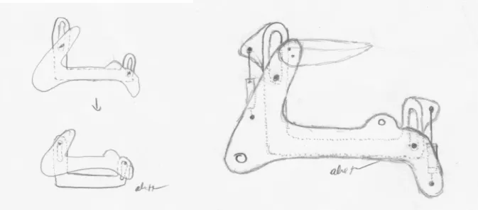
Rory Aronson’s Initial Whole Concept
This concept, seen in Figure 5.9, is inspired by IKEA flat pack packaging. The goal here was to make the entire chair collapse down into 1 flat package with the wheels removed such that it could fit into a car very easily. As an added bonus, the folding mechanism allows the user to lower themselves from the high transfer position to a low driving position.
We learned from this design that a folding backrest will be a necessary feature to fit the device in the car, and that lowering the user only halfway to the ground is simply inadequate to reach our requirement of providing the full beach experience.
Figure 5.9: Rory’s initial whole concept.
Marco Pietsch’s Initial Whole Concept
This design, seen in Figure 5.10, features 3 balloon tires with a very long wheelbase. The user sits in the back where the two big wheels are located. One small wheel is added in the front. The seat can move up and down with the lever design and is powered by a pneumatic spring. Other features include hand cranks and a rim belt to move the chair. The frame could be built very lightweight. The largest drawback is that the chair itself makes it difficult for the user to leave the chair when at the level of the beach.
Figure 5.10: Marco’s initial whole concept.
Marvin Rimmele’s Initial Whole Concept
As seen in Figure 5.11 this wheelchair is based on the three-wheel design with the third wheel in the front. The big differentiation to the other concepts is to use the big fat snow tires as driving wheels. They have been proven successful in the mountain bike scene. The front wheel is a small balloon tire that has enough surface area to prevent it from digging into the ground and flatten the sand to have less resistance whilst driving. This concept can basically be combined with different kind of driving systems, but the original idea is to use a lever drive with mechanical disc brakes at the levers.
This concept can be adjusted into a very flat position so you can fold down the seats backrest. Also you can disassemble the front wheel with the axis plus the driving wheels with quick release. Therefore the whole wheelchair will fit into a very small trunk easily. In addition, ADA doorways shouldn’t be a problem either because of the snow tires, in comparison to the balloon tires.
Max Hessel’s Initial Whole Concept
As seen in Figure 5.12 this design consists of four wheels. The part that separates it from a classical wheelchair is that the two big driven mountain bike tires are in the front. Those tires are significantly slimmer than the balloon tires and give us the possibility to operate the wheelchair inside buildings without big problems. In the back there are two smaller balloon tires which are on the same horizontal axis. Those tires work as one and could therefore be replaced by a bigger balloon tire. The wheels are dragged like shopping cart wheels and are fully able to turn about a vertical axis 360°.
To make it easy for the user to move the wheelchair there is a lever attached through a free run to each of the front wheels. That makes it easy to operate and increases the force for better movement in the sand. Attached to the mountain bike tikes there are two disk brakes, which provide great braking power and are operated from the top of the levers. This gives the user always the possibility to break without having to change his grip. Additionally to the safety benefits blocking one wheel and driving the other makes it possible to have a good maneuverability despite the front wheels being driven.
Missing any way to adjust the seat in horizontal and vertical direction it’s very hard for the user to get in and out of the wheelchair. This problem is being enhanced by the big wheels and the levers that are directly in the normal transfer position. In all of our later concepts we used a lever mechanism to adapt the seat position and provide an easier transfer.
Initial Whole Concept Matrix
The above whole concepts were put into a matrix and each team member scored each concept based on the engineering specifications as criteria (Table 5.1). Then, we went through as a team and discussed discrepancies in the scoring from each person. Table 5.2 shows the average total score for each design.
Table 5.1: Initial whole concept matrix criteria and weighting.
Category User Need Engineering Specification (DATUM) Weight
Geometric Width fits through ADA doorway 32 inches (max) 5
Adjustable leg rest length Adjustable by 6 inches (min) 2
Adjustable leg rest angle 0 to 90 degrees 2
Collapsible Back rest folds 180 degrees 4
Removable wheels Without tools 5
Fit into a hatchback trunk 30.25" X 35" X 32" (max size) 5
Motion and Kinematic Steepest slope it can climb 1:10 slope (min) 4
Max speed 2 mph (min) 3
Gear Ratios 2 2
Water Propulsion 0.25 mph 2
Force and Torque Weight capacity 250 pounds (min) 4
Arm force required 10 pounds per arm (max) 5
Braking on slope 1:6 slope (min) 4
Floating Stability User cannot tip over 5
Floats the user adequately 250 pound buoyancy force (min) 3
Materials Rust and corrosion resistance 5 years (min) 4
Runs on sandy, wet, grassy and rocky terrain without breaking
4
Safety Shin, waist and lumbar straps All 3 2
Pinch points 5 (max) 2
Production Off the shelf components 80% (min) 2
Use of stock materials 80% (min) 1
Assembly
Must be simply and easily
assembled (pieces) 10 separate pieces (max)
3
Must be simply and easily
assembled (tools) 2 tools required (max)
2
Transportation Number of greasy parts 0 (max) 1
Number of loose parts that could be
lost 0 (max)
2
Number of wires or cables to get
caught 0 (max)
2
Individual piece weight 25 lb. (max) 5
Operation Move arm rests for transfers Both arm rests rotate up 90 degrees 4
Must go into the water 2 feet (min) 5
Hand operated braking force Arm force required to move the chair (max) 4
Turning force Arm force required to move the chair (max) 5
Cushion thickness 1.5 inches (min) or equivalent 3
Maintenance Washable/Rinse off Non-porous materials 3
Easily Maintenance 3 tools required (max) 2
Maintenance Once per year (max) 1
Cost Cost $1000 (max) 2
Environmental
Materials degrading into the
environment 0
3
Leaking grease 0 2
Quality Life span 5 years (min) 4
Standard sized and removable
cushion or space for one 18" X 16" X 2-4"
1
subsystems and clearly choosing better and worse options, the team decided to go back and iterate on their designs, which is seen in the next section.
Table 5.2: Results of the matrix
Concept Total Average Score
Avila Manual Chair -52 Avila Electric Chair -46 Rory’s Concept 29.75
Sam’s Concept 45
Josh’s Concept
6 - Iterated Whole Concepts
Based on the matrix results and discussion from the initial whole concepts, the team iterated the designs and came up with new designs to be further evaluated. Most designs were very similar and we chose two to be considered for the final concept. These two are detailed below along with a description of the final selection process.
Rory Aronson’s Iterated Whole Concept
The main advantage of this design, seen in Figure 6.1, over the first design by Rory is the ability to lower the user all the way to the ground. This required removing the center strut and the 3-wheel design in favor of 4 3-wheels with the frame members on the sides of the user. This design incorporates a seat lowering mechanism with a gas piston located underneath the frame. The design features hand cranks and a belt drive as well as foldable foot rests for an unobstructed path to the sand from the lowest seat position.
Marco Pietsch’s Iterated Whole Concept
The main disadvantage of the old design is the closed frame, which makes it very uncomfortable to leave the wheelchair at ground level. Because of this, we moved the single wheel into the back as seen in Figure 6.2. The seat can move up and down with the same lever design, powered by a pneumatic spring. We use hand cranks and a rim belt to move the chair. The center of gravity is almost exactly between the two axes of the wheels. We are afraid the back wheel is going to dig into the sand and the forces on the front wheels are maybe not enough to prevent the wheels from spinning in the sand.
Final Selection Process
The team got itself into quite the time crunch and made the final concept decision just 2 days prior to this report being submitted. We had a videoconference over the weekend and talked about the advantages and disadvantages of the two designs. The designs were very similar in many aspects, but the following reasons are what made the team choose Rory’s design.
● Marco’s design would be less stable due to only having 3 wheels.
● Marco’s design places too much of the users’ weight on the steering wheel.
○ This causes this smaller wheel to dig into the ground and makes steering more difficult.
○ This also causes less weight on the drive wheels and a potential loss of traction. ● Rory’s design places more of the users’ weight on the driving wheels.
○ This allows for greater traction and easier steering.
7 - The Final Concept
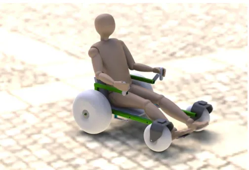
Figures 7.1, 7.2, 7.3, and 7.4 illustrate our final concept design and discussion is in the following sections.
Figure 7.1: Final concept design sketch.
Figure 7.3: CAD render of the final concept design in the transfer position.
Satisfying User Requirements
For this design to be a success, two main requirements must be met: 1. Letting the user have a full beach experience.
2. Allowing the user to enjoy the experience with as much independence as possible. There are numerous other requirements, but they all end up under these main two. Because there already are beach wheelchairs on the market, we also need the wheelchair to be just as good or better in every aspect possible.
The way we satisfied the first main requirement of allowing the user to have a complete beach experience, is through the seat lowering mechanism. This subsystem came up through brainstorming ideas on how people enjoy the beach. These ideas included playing in the sand, lounging/sunbathing, and being in the water. Because all these activities involved being close to the ground, a lowered seat was designed. The low seat would allow the user to be close to the sand, lounge, and have a low center of gravity so that floating in the water would be possible. Because the user needs to be able to transfer easily into the device, the height of the seat had to be high and this resulted in a design that could adjust between the high and low positions. The second main requirement was that the device needs to able to be operated fairly independently. The features that we designed into the device to help satisfy this requirement was that it could fit into a minivan, was lightweight, and could be operated without too much difficulty. We were able to design the device to fit in a minivan by having detachable wheels and foldable parts. Lightweight construction was achieved by having a simple frame and selective materials. Operation of a wheelchair through sand is very difficult, so in order to have a device that could be used with only a little effort we decided on a hand crank as the operating mechanism with a gear ratio that made it easier to travel across sand.
The 4 balloon tires are evenly placed around the user and provide enough upward force and stability to float. The floating stability increases when the user lowers the seat, which leads to a low center of gravity.
In order to provide independence, we need the wheelchair to be as light as possible. We therefore considered this in nearly all the subsystem matrices and decided to build the Wheelchair out of Aluminum. For the combination of high strength and low weight we determined welding as the right way to join our frame.