Systematic Construction of Software Architecture Supported by
Enhanced First-Class Connectors
Abdelkrim Amirat1,2 and Mourad Oussalah1
1LINA Laboratory LINA CNRS UMR 6241, University of Nantes, France 2University Center of Souk Ahras, Algeria
E-mail: {abdelkrim.amirat; mourad.oussalah}@univ-nantes.fr
Keywords:logical architecture, physical architecture, first class connector, connection manager, modelling software architecture, C3 metamodel
Received:November 10, 2008
To provide hierarchical description from different software architectural viewpoints we need more than one abstraction hierarchy and connection mechanisms to support the interactions among components. Also, these mechanisms will support the refinement and traceability of architectural elements through the different levels of each hierarchy. Current methods and tools provide poor support for the challenge posed by developing system using hierarchical description. This paper describes an architecture-centric approach allowing the user to describe the logical architecture view where a physical architecture view is generated automatically for all application instances of the logical architecture.
Povzetek: Prispevek se ukvarja s povezovalnimi mehanizmi za podporo interakcijam med komponentami na področju programskega inženirstva.
1
Introduction
Modeling and representation of software architectures are the main phases of the development process of complex software systems [36]. The representation of an architecture is based on the concepts of component (loci of computation), connector (loci of communication), and configuration (arrangement of components and connectors, and properties of that arrangement) in order to describe the structure of the system at a higher level of abstraction than objects or lines of code. This representation provides several advantages over the life cycle of a software [10].
Components have always been considered to be the fundamental building blocks of software systems. The ways the components of a system interact are determinant for establishing the global system properties that emerge from the way the individual components are interconnected. Hence, component interactions have been promoted to first class design entities as well, and architectural connectors have emerged as a powerful tool for supporting the design of these interactions [29, 32].
Although the use of connectors is widely accepted at the conceptual level, their explicit representation at the implementation level is not always left to be necessary. For example, the Darwin [14] architecture description language does not include connectors. However, we feel that distinct conceptual entities should correspond to distinct implementation entities, so that they can truly become first-class and be manipulated as such. In fact, as argued in [20], the current level of support that ADLs provide for connector building is still far from the one awarded to components. For instance, although a considerable amount of work can be found on several
aspects of connectors [2, 20, 33, 35]. Further steps are still necessary to achieve a systematic way of constructing new connectors from existing ones. Yet, the ability to manipulate connectors in a systematic and controlled way is essential for promoting reuse and incremental development, and to make it easier to address complex interactions.
Certainly, having a representation of the software architecture allows an easy exchange between the architect and programmer. Also, during the phases of maintenance and evolution, this representation helps to locate defects and reduces the risk of improper assembly of a new feature in the system. In addition, the distinction which exists between components and connectors allows a more explicit representation between the functional aspects and these of communication and therefore, makes the system easier to understand and to change. Finally, architecture-based components are also useful to facilitate the reuse of certain parts of the system represented by configurations [1].
generation” of ADLs. The classification of ADLs in generations has been introduced by Medvidovic [19].
In this article, we take a step towards this goal by proposing a metamodel for the description of software architecture called C3 (three “C” for Component, Connector, and Configuration). The specificities of this metamodel are: First, proposing a new structure and new types of connectors, second, definition and manipulation of configurations as first classes entities and third, description of architectures from two different views, a model architecture view (logical architecture) created by the architect and an application architecture view (physical architecture instances of the logical architecture) generated automatically which serves as support to maintain the consistency and the evolution of the application architectures.
After this introduction, the remainder of this article is organized as follows: Section 2 provides the motivations of our research. In section 3 presents the concept of a logical architecture with the key elements of the proposed metamodel. The physical architecture is defined in section 4. The last section concludes this work with a summary of our ongoing research.
2
Motivations
Our main motivation is to propose a metamodel to maintain the consistency of an architecture using new types of connectors with a richer semantics. Using these connectors, systems are built like a Lego Blocks (Puzzle) by assembling components and connectors, where each element can be only placed in the right place in the architecture puzzle. We find in most existing ADLs and notation languages that:
The definition and instantiation of connectors are often merged in a single operation.
The management of connectors does not take into account the semantic composition hierarchies when positioning and establishing links between components and their composites.
Few models allow reuse connectors (for example through inheritance) and to define new connectors by their reuse.
There is no direct and automatic correspondence between architectures (models) and applications built following these architectures (instances).
In order to overcome these shortcomings we propose in this paper, a metamodel (C3) for describing hierarchical software architecture, based on the definition of two types of architecture. A logical architecture defined by the user and a physical architecture built by the system and conforms to the logical architecture. The metamodel will make its contribution towards the following objectives:
O1:Provide a higher abstraction level for connectors in order to make them more generic and more reusable.
O2:Take into account the semantics of several types of relationships. In our case; we explore the
association relationship between components, the composition relationship among architectural elements, and the propagation relationship to describe software systems at different levels of details.
O3: Promote the maintenance and the evolution of architectures by the possibility of adding, deleting and substitution of different elements in the architecture.
O4: The principle of reuse should be widely exploited. New components and connectors can be defined by combining already existing elements through inheritance and/or composition mechanisms. Basically, we have defined a set of generic, reusable connectors and extensible to support new structural and behavioural relations among components. O5: Explicit connectors must be preserved through a
declarative interface that hides the management mechanism of the inside glue-protocol.
O6: Using the physical and the logical architecture, we can separate the functional aspects of architectural elements and the non-functional aspects related to the management of their consistency.
3
Logical Architecture (LA)
Our approach is based on the description of software architecture following two architectural views. The first one is a logic view defined by the architect by assembling the compatible elements available in the library of element types and the second one is a physical view constructed automatically by the system and serves as a support for user applications built in accordance with the logical architecture.
The large majority of ADLs consider components as entities of first class. So, they make a distinction between component-types and component-instances. However, this is not the case with other concepts such as connectors and configurations. In our metamodel we consider each concept recognized by the C3 metamodel as an architectural element of the first class citizen. So, each architectural element may be positioned on one of the three abstraction levels defined in the following section. We believe that it is necessary to reify the core architectural elements in order to be able to represent and manipulate them and let them evolve easily.
3.1
Abstraction levels
In our approach, software architectures are described in accordance to the first three levels of modelling defined by the OMG [23, 24]. The application level (A0) which
represents the real word application (an instance of the architecture), the architecture level (A1) which represents
the architecture model and meta-architecture level (A2)
3.1.1
Meta-architecture level (A
2)
In this level we find the standard definition of any architectural element proposed by a large set of ADLs to describe software architectures. We consider the most common elements namely components, connectors, and configurations. Section 3.2 will summarize the description of the core elements of the C3 metamodel.
3.1.2
Architecture level (A
1)
This level is used to describe any architecture model using one or more instances of architectural building blocks defined at the meta-architecture level (A2). Figure
1 shows a client/server architecture configuration (CSconfig) type which is defined using the following three components types: client component type, server component type and data base component type; and two variants of RPC connector types: N1between the client type and the server one, and N2 between the server type and the data base type.
3.1.3
Application level (A
0)
At this level (implementation level) one or more applications can be built according to the architecture described at the above level (A1). Each architectural element of the implementation level is an instance of an element-type of the architecture model. For example we can build from the previous client/server architecture the application SCapp(Figure 1) which is an instance of the CSconfig configuration assembled from C1 and C2 instances of the client component; DBOracleinstance the Data base component; S1 instance of the server component; N11and N12 instances of connector type N1 and finally N21instance of connector type N2. This figure shows only one application architecture (CSapp), more application architectures could be instantiated.
We have presented in this section the concept software architecture through its core concepts and its various abstraction levels. We have focused on the
important concepts to address the key issue of connectors in software architecture description.
3.2
Basic concepts of C3 metamodel
3.2.1
Architectural elements
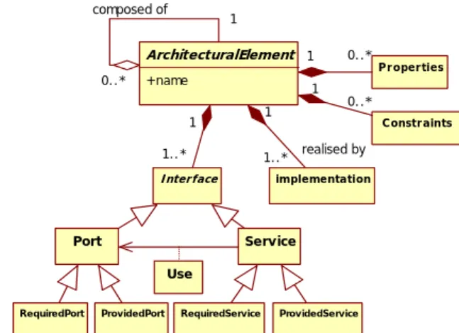
In our metamodel described in Figure 2, an architectural element may be a component, a connector or architectural configuration1. A configuration represents a graph of components and connectors. A component or a connector is a composite when it is composed of other internal architectural elements. A component or connector is primitive when it is atomic (without internal structure).
An architectural element may have several properties as well as constraints on these properties, as it may have one or more possible implementations. The interaction points of each architectural element with its environment are the interfaces. Each architectural element is defined by its interfaces through which they publish its required and provided services to and from its environment. Each service may use one or more ports. We approach in the following sections with more detail the most important concepts of our C3 metamodel.
3.2.2
Component
A generally accepted view of a software component is that it is a software unit with provided services and required services. The provided services are operations performed by the component. The required services are the services needed by the component to produce the provided services. The interface of a component consists of the specifications of its provided and required services. It should specify any dependenciesbetween its provided and required services. To specify these dependencies precisely, it is necessary to match the required services to the corresponding provided services. Services are carried using ports. Thus, we can define a generic interface of a component type as follows:
ComponenttypeName ( requiredInterf , provideInterf);
3.2.3
Connector
Connectors are architectural building blocks used to model the interactions between components and rules that govern these interactions. They correspond to lines in box-line descriptions. Examples are pipes, procedure call, method in-vocation, client-server protocol, and SQL link between database and application. Unlike components, connectors may not correspond to compilation entities. However, the specifications of connectors in an ADL may also contain rules to implement a specific type of connectors. In general connectors have been developed without regard to reuse or extension. Current ADLs can be classified into three different kinds: 1- ADLs without connectors, ADLs with
1“Architectural configuration” will, at various times in this paper, be
referred to simply as “graph” or “topology”. Legend: Required Port, Provided Port
Figure 1: Architecture abstraction levels.
C1
Client
Configuration
Component
…
ConnectorServer A2
DataBase CSconfig
S1 DBOracle
CSapp C2
Instance-Of
Instance-Of
…
N
1N
2N
11N
21N
12A
1A0
predefined set of connectors, and ADLs with explicit connector types.
ADLs with implicit connectors. There are ADLs that prefer the absence of connector because they distort the compositional nature of software architectures. Some ADLs, such as Darwin [13], Leda [6], and Radipe [11]do not consider connectors as first class citizens. However these ADLs make difficult the reusability of components because they have the coordination process tangled with the computation inside them, and they are aware of the coordination process that has to happen in order to communicate with the rest. The notion of connector emerges from the need to separate the interaction from the computation in order to obtain more reusable and modularized components and to improve the level of abstraction of software architecture description [18]. Mary Shaw [32] presents the need for connectors due to the fact that the specification of software systems with complex coordination protocols is very difficult without the notion of connector. Hence, connector provides not only a high level of abstraction and modularity to software architectures, but also an architectural view of the system instead of the object-oriented view of compositional approaches. So, it is important to defend the idea of considering connectors as first-order citizens of ADLs.
ADLs with predefined set of connectors. UniCon [33, 34] is a typical representative of ADLs supporting a predefined set of built-in connector types only. The semantics of built-in connector types are defined as part of the language, and are intended to correspond to the usual interaction primitives supported by underlaying operating system or programming language. A connector in the UniCon language is specified by its protocol. A connector’s protocol consists of the connector’s type, specific set of properties, and a list of typed roles. Each role serves as a point through which the connector is connected to a component. UniCon currently supports seven built-in connector types which represent the basic classes of interactions among components: Pipe, FileIO, Procedure Call, Remote Procedure Call, Data Access, RT Scheduler, and PL Bundler. These connectors cannot be instantiated nor evolved. Composite connectors are composed only from connectors.
ADLs with explicit connector types. Most ADLs provide connectors as first order citizens of the language such as: ACME [10], Aesop [8], C2 [15, 16, 17], SADL [21], Wright [1], ArchWare’s π-ADL [26, 27], xADL [7], AADL [3] etc. All of these languages go a step forward with regard to the previous kind of ADLs. They improve the reusability of components and connectors by separating computation from coordination.
In our approach we opt for the third category of connectors (explicit connector types). So, in the C3 metamodel we present some explicit and generic types of
connectors that the user can specialize following her/his needs in each application field. We will focus with details on this concept in section 3.3.
3.2.4
Configuration
A configuration represents a graph of components and connectors. Configuration specifies how components are connected with connectors (Figure 3). This concept is needed to determine if the components are well connected, whether their interfaces agree, and so on. A configuration is described by an interface which enables the communication between: the configuration and its external environment, and the configuration and its internal components.
Configuration typeName (requiredInterf, provideInterf); The following UML diagrams (Figure 2 and 3) represent the main elements of C3 metamodel. For clarity reason, these diagrams present a simplified version of our metamodel. In the rest of this article we will only deal with connectors with more detail as they represent the mainstream of our research topic in this paper. In addition, the relationship connector-configuration and connector-component will be highlighted in the text.
Figure 2: Structure of an architectural element in C3.
Figure 3: Component, connector, and configuration in C3.
3.3
Connector in C3
A connector is mainly represented by an interface and a gluespecification [28]. Basically, the interfaceshows the necessary information of the connector, including the number of interaction points, service type that a connector provides (communication, conversion,
ArchitecturalElement
+name
implementation
realised by 1
1..*
Constr aints
1 0..*
P r oper ties
1 0..* composed of
0..*
1
Interface
1
1..*
Port Service
RequiredService ProvidedService Use
RequiredPort ProvidedPort
ArchitecturalElement
Configur ation
+name
C omponent
+name
Connector
+name 1..* 1..*
ECC C CDC
CC
coordination, facilitation), connection mode (synchronous, asynchronous), transfer mode (parallel, serial) etc. In C3 interaction points of an interface are called Ports. A port is the interface of a connector intended to be tied to a component interface (a component’s port). In the context of the frame, a portis either a provided portor a required port. A provided port serves as entry point to a component interaction represented by a connector type instance and it is intended to be connected to the required port of a component (or to the required portof another connector). Similarly, a require port serves as the outlet point of a component interaction represented by a connector type instance and it is intended to be connected to the provide port of a component (or to the provide role of another connector). The number of ports within a connector denotes the degreeof a connector type. For example, in client-server architecture a connector type representing procedure call interaction between client and server entities is a connector with degree two. More complex interactions among three or more components are typically represented by connector types of higher degrees. Consequently, the interface is the visible part of connector; hence it must contain enough information regarding the service and the type of this connector. By doing this, one can decide whether or not a given connector suits its qualifications by examining its interface only.
The glue specification describes the functionality that is expected from a connector. It represents the hidden part of a connector. The glue could be just a simple protocol links ports or it could be a complex protocol that does various operations including linking, conversion of data format, transferring, adapting, etc. in general the glue of a connector represents the connection type of that connector. Connectors can also have an internal architecture that includes computation and information storage. For example a connector would execute an algorithm for converting data from format A to format B or an algorithm for compressing data before it transmits them. Hence, the service provided by connectors is defined by its glue; the services of a connector could be either communication service, conversion service, coordination service, or facilitation service.
In case of composite connectors the sub-connectors and sub-components of the composite connector must be defined in the glue, as well as the binding among the sub-connectors and sub-components.
The general signature form of the connector interface is a follows:
Connector typeName (requiredInterf, provideInterf);
3.3.1
Connector structure
Our contribution at this level consists in enhancing the structure of connectors by encapsulating the attachment links (figure 4). So, the application builder will have to spend no effort in connecting connectors with its
compatible components and/or configurations. Consequently, the task of the developer consists only in choosing from the library the suitable type of connectors where its interfaces are compatible with the interfaces of component/configuration types of which are expected to be assembled.
Figure 4: Connector structure.
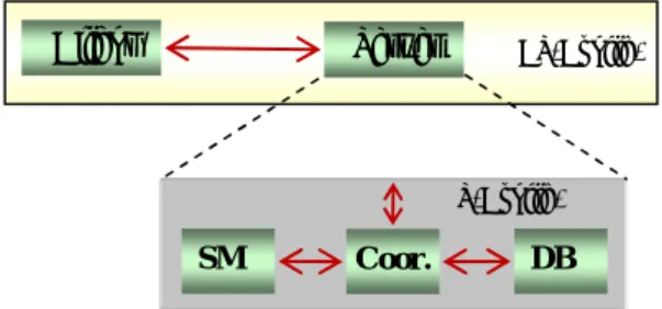
In order to illustrate the properties of C3 metamodel and the associated connector definition, a case study is going to be used throughout the paper. The case study is a client-server configuration (CS-config) organized around a client-server relationship. In this configuration we have a client and a server. The server component itself is defined by a configuration (S-config) whose internal components are Coordinator (Coor.), securityManager (SM) and dataBase (DB). These elements are interconnected via connector services that determine the interactions that can occur between the server and client on one hand and between the server and its internal elements on the other hand. These connectors are represented in Figure 5 by solid-lines.
Figure 5: Client–Server Architecture.
In Figure 6.a we describe the structure of the RPC connector used to connect the client component (C) with the server component (S). In this new structure the RPC connector encapsulates attachments that represent links between the client and server.
Figure 6.a: Connector structure in C3.
Connector
Interface Connection Glue
Port
Service Role
Connector (RPC)
Glue
Server (S) Client(C)
Attachment
New structure of a connector
Old structure of a connector
Legend: Required Port Provided Port Required Role Provided Role
Link
CS-Config.
S-Config. Client
DB
SM Coor.
Figure 6.b: Connector description in C3.
Figure 6.b represents the signature specification of the connector RPC. Inside this connector type we have the glue code which describes how the activities of the client and server are coordinated. It must indicate that the activities should be sequenced in a well defined order: the customer asks for a service, the server processes the request, the server provides the result and the customer gets the result.
So, by encapsulating attachments inside connectors and having well defined connector interfaces with previously known element types to be connected by each connector type components and/or configurations are assembled in an easy and coherent way in the form of an architectural puzzle (Lego Blocks) without any effort to describe links among components and connectors or between configurations and connectors. Consequently, this approach accelerates the development of component-based systems, improves their evolution, coherence, maintainability and promotes component markets [4].
3.3.2. Connector taxonomy
In C3 we have defined three connector types as illustrated in Figure 3: the connection connector type (CC), the composition decomposition connector type (CDC), and expansion compression connector type (ECC). Each type has its own semantic and has the following signature form:
Connector typeName(requiredInterf, providedInterf);
Where requiredInterf represents all required ports and services and providedInterf represents all provided ports and services of a connector. Obviously each interface also contains services, but in the following definitions we focus only on structural aspect of the interface (ports). The functional aspect (services) will not be addressed in this paper and therefore they will not be specified in the descriptions that follow. Consider that each service can use one or more ports of the same interface. In the following we give the exact function of each type of connector in C3 metamodel.
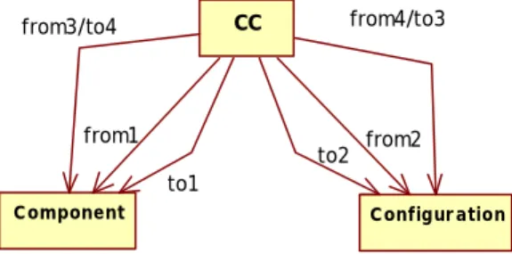
Connection connector (CC)
CC connector type is used to connect components and / or configurations belonging to the same level of decomposition (the same abstraction level) as illustrated by Figure 7.a. The ports of this type of connector can be
“required” or “provided”. Thus, through these ports elements can exchange services between them.
Connector CC ( {Xi.requiredPort}, {Yj.providedPort} )
where Xi, Yj
{component, configuration},Xi, Yj
Lk; // the same hierarchical level (Lk), Xi.Level = Yj.Level, withi = 1, 2, .., M ; j = 1, 2, .., N, k = 1, 2, .., R.
Where (M+N) is the maximum number of elements which can be linked by CC connector. Hence, CC may have to (M+N) ports. The mapping between the inputs and outputs is described by an exchange protocol called glue defined inside of the connector. The various possibilities of links that a connection connector can have are depicted in Figure 7.a.
Figure 7.a: Possible links of CC Connector
Figure 7.b represents CC1 a connection connector type used to link a client component with s-config configuration of the previous example. This type connector has two ports: portC1 in client side and portS1 in server side. Hence, the interface CC1will be defined as follows:
Connector CC1(portC1, portS1);
Figure 7.b: Connector CC1 in client-server architecture
Composition / decomposition connector (CDC) CDC connector type is used to realize a top-down refinement (i.e. to link a configuration with its internal elements) also we call this relationship a decomposition model. Likewise CDC connector can be used to realize bottom-up abstraction (i.e. to link a set of elements to their container or configuration) also we call this relationship a composition model. However, this type of connectors can play two semantic roles with two different glue protocols. The first one is the decomposition process of a configuration and the second one is composition process of a configuration.
CC
Configur ation Component
from1
to2 to1
from3/to4 from4/to3
from2
CC1
Client S-Config
portS1 portC1
Legend: Component Connector Required Port Provided Port Connector RPC( C.P1, S.P1 ) // Connector interface
{
Proprieties= { List of properties };
Constraints= { List of constraints }; Services= { List of services };
HierarchicalLevel= (C.Level = S.Level); //decomposition level Glue= {Roles={{R1 , R2}; R1 = R2 }}; // simple case of a glue Attachments= { R1 toC.P1, R2 toS.P1 }; //attachments
Decomposition of a configuration X to its internals
Connector CDC( X.requiredPort, { Yi .providedPort} );
Composition of Yielements to constitute a configuration X
Connector CDC( {Yi.requiredPort}, X.providedPort );
where X is a configuration,
Y
{component, configuration}, i =1,2,..,N , X
Lkand Yi
Lk-j(i.e. X.Level > Yi.Level) Lkis the hierarchical level.Thus, a CDC connector will have (N+1) ports, where N is the number of internal elements in the corresponding configuration. This type of connector has the following interests: first it allows us to shape the genealogical tree of the different elements deployed in an architecture, second it enables a configuration to spread information to all these internal elements without exception (to-down propagation) and inversely (i.e. it allows any internal element to send information to its configuration). Therefore, when designing this type of connector we can choose to define the glue corresponding to the decomposition function or that corresponding to the composition function. Also, we can define glue corresponding to the two functions together in the same connector type. Figure 8.a represents the possible links that a CDC connector type may have in a given architecture.
Figure 8.a: Possible links of CDC Connector
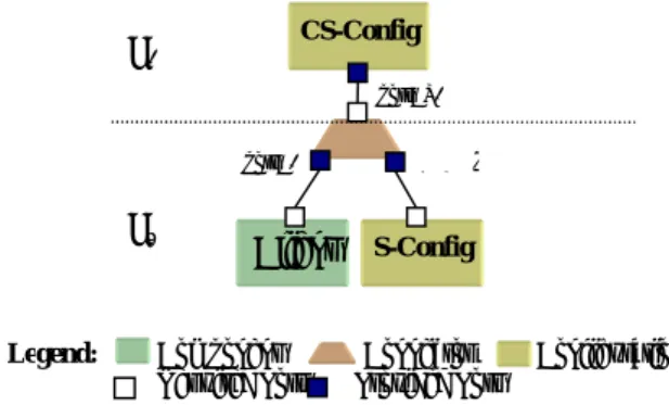
Figure 8.b represents CDC1 a decomposition composition connector type used to link client-server configuration (CS-config) defined at the hierarchical level (L2) with its internals namely client component (Client) and server configuration (s-config) defined at the lower hierarchical level (L1). Consequently, the interface of CDC1 connector type will be specified as follows:
ConnectorCDC1( portCS2, portC2, portS2);
Where portC2, portS2, and portCS are respectively used to connect CDC1 with the client component, the server configuration, and client-server configuration (CS-config).
Figure 8.b: Possible links of CDC1 connector
Expansion/compression connector (ECC)
The ECC is used to establish a service link between a configuration and its internal elements. Also, ECC can be used as an expansion operator of services to several sub-services and it can be used in reverse as a compression operator of set of services to a global service. The CDC may have an interface for expansion and another for compression. So, these interfaces are defined as follows:
Expansion role
Connector ECC ( X.requiredPort , { Yi.providedPort }
) ;
Compression role
Connector ECC ({ Yi.requiredPort } , X.providedPort
) ;
where X is a configuration,
Y
{component, configuration},i =1,2,..,N, and N ≤ number of internal elements. X
Lk et Yi
Lk-1; (i.e. X.Level > Yi.Level) L is the hierarchical level.ECC connector type can be implemented using either single glue for one function (expansion or compression) or using two separate glues for expansion and compression functions. This will depend on the design decision.
Figure 9.a represents the various possibilities of connections that an ECC connector type can have in a given architecture. So, in this case the configuration config0 contains two components (comp1 , comp2) and
two configurations (config1, config2) but config0 have
only two service relationships with comp1 and config1
and no service relationship with comp2and config2.
CDC
Component
Configuration1
to1
from2 from1
Configuration2
to2
CS-Config
S-Config Client
L2
L1
portCS2
p ortS2 portC2
Legend: Component Connector Configuration Required Port Provided Port
L
Figure 9.a: Possible links of ECC connector
Figure 9.b illustrates the connector type ECC1 which allows exchange of information between the server configuration (s-config) and the coordinator component (Coor.). Thus, to achieve a bidirectional communication between the server and coordinator, ECC1 must have the following ports:
portS3 and portCo1 are used to ensure the expansion function from the server to coordinator. The portCo2 and portS4 are used to ensure compression function. The interface of this ECC1 type will be as follows:
ConnectorECC1 (portS3, portCo1, portS4, portCo2) ;
Figure 9.b: Possible links of ECC1 connector in client-server architecture
4
Physical Architecture (PA)
The physical architecture is a memory image of the application instance of the logical architecture. This image is built in the form of a graph whose nodes are instances of a connections manager. Each instance created corresponds to a component or a configuration instanced to construct the real application. Nodes of this graph are connected by arcs. We have three types of arcs. Each type of arc corresponds to specific type of connector. The physical architecture is built to serve as support for updating and evolution operations of the application instance like addition, removal, and replacement of elements in the application instance.
4.1
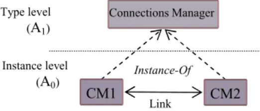
Connections Manager (CM)
The physical architecture is described using only two levels of abstractions; model or type level and level instance level as illustrated in Figure 9.a. In the type level we have the connections manager type represented by a class that encapsulates all different link of information on the links that a component or a configuration may have with its environment.
Figure 10.a: Abstraction levels in physical architecture
Each CM is identified by a name and has four attributes as indicated in Figure 10.b.
Figure 10.b: Structure of a connections manager
• ElementName: represents the name of the architectural element associated with this CM (i.e. the name of the component or the configuration corresponding);
• CC_Links: list of connection connector names connected to the element associated with this CM;
• CDC_link: the name of the composition decomposition connector connected to the element associated with this CM;
• ECC_Link:the name of the expansion compression connector connected to the element associated with this CM;
4.2
Operations on Connections Manager
The possible operations on the connections manager are:
• Instantiation: the connection manager is instantiated at the instance level (A0) of the physical architecture. Whenever a configuration or component is instantiated at the application level the associated CM is automatically created in the physical architecture.
• Installation: each time a connector is installed at the application level between a set of element instances, so the attributes of the associated CMs are updated with the necessary information about this connector instance.
connectorManager Name
{
ElementName: string ;
CDC_Link : string ;
CC_Links : list ; ECC_Link : string ;
} Instance level
(A0) Type level
(A1)
Link
Instance-Of
CM2 CM1
Connections Manager
ECC 1 S-Config
Coor. portS3
portCo1 portS4 portCo2
Compression
Expansion Expansion
Compression
Legend: Component Connector Configuration Required Port Provided Port
Li-1
config0
comp1 config1
from
comp2 config2
ECC
• Propagation: the mechanism of propagation is used to update information about links needed between CMs. These links are published by the interface of the connector installed at the application level.
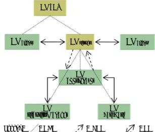
The physical architecture corresponding to the application instance of client-server architecture is illustrated in Figure 11. In this application we assume having two clients connected to a single server.
Figure 11: Physical architecture of client-server application .
Once the application is built by the user, the corresponding physical architecture is also built in parallel. Thereafter if we need to intervene on the application to maintain or evolve it we must locate the concerned elements on the physical architecture using graph searching routines and graph updating operations like add (node), delete (node) or replace (node).
Finally we can represent the logical architecture (LA) and the physical architecture (PA) and their relationship by an architecture model described in C3 metamodel. Thus, the LA and the PA are represented by two components and the relationship between them by a connection connector (Figure 12). Any action performed at the LA level causes a sending a message to the PA level. This message will be interpreted as an action to be performed by the PA. Exchanged messages (services) between these two types of architectures are:
A component instantiation at the LA level causes sending a message “CM_creation” from LA
interface (LI) to PA. When this message is received by the PA interface (PI) a connection manager instance will be created to represent this component at the PA level.
A connector instantiation at the LA level causes sending a message “CM_connection” from LA to PA. When this message is received by the PA a set of links are created to link CM instances corresponding to all components connected by this connector instance.
Any updating action at the LA level causes sending a message “CM_update” from LI to PI. When this message is received by the PA a set of updating operations are performed to rearrange links among the corresponding CMs.
5
Conclusion
In this article we have presented the core elements of C3 metamodel and how to describe software architecture using C3. The elements defined by C3 are assembled through their interfaces to build software architectures. So, we must ensure syntactic checks by checking the compatibility of interfaces types of various elements assembled in the architecture and are in interaction with each other.
Mainly, our approach is defined by two types of architectures. A logical architecture described by the architect. And a physical architecture generated automatically by the system. The logical architecture uses architectural concepts most commonly accepted by all ADLs namely components, connectors and configurations.
We found interesting to give a new structure for connectors in which attachments are encapsulated within the definition of connectors. Hence, the interface connector is now a set of services and ports. This new structure allows us to assemble connectors only with elements that are defined in its interface.
We have defined a set of generic, reusable connectors and extensible to support new structural and behavioural relations among components and we have identified three types of connectors. Connection Connectors (CC) which refer to the links among components belonging to the same level of decomposition. Composition / Decomposition Connectors (CDC) which refer to the links between a configuration and its internal components and connectors. Expansion/Compression connectors (ECC) which refer to the links used to realize any transformation of information or data exchanged between a configuration and its internal components.
Also, we have defined a physical architecture as a graph whose nodes are connections managers associated with architectural elements and arcs represent links that correspond to the connectors. The physical architecture reflects the application architecture which is an instance of the logical architecture and serves as a support for maintenance and evolution operations applied on architecture of the application.
Legend: : CDC : ECC : CC CM_CS
CMserver CMclient1
CM coordinator
CM
securityManager dataBaseCM CMclient2
Legend:LI: logical interface, PI: physical interface
Figure 12: Architectures relationship.
Logical Architecture
A0Level
A1Level
A2Level
Connection
LI PI
Physical Architecture
As extension for this work, we planned to define more than one hierarchical view to describe component-based architectures. Among those hierarchies we will use a structural hierarchy to develop the structural aspects of any architecture described according to C3 metamodel, a behaviour hierarchy to make explicit functional aspects of the system, a conceptual hierarchy to clarify the relationships between different elements types developed by the architects and stored in libraries, and metamodeling hierarchy to define the core elements of our C3 metamodel and locate its position in the pyramid of abstraction levels defined by OMG’s standards. Obviously, we will focus also on the relationship between these hierarchies, and the different connection mechanisms used to enable interactions between elements from different hierarchy views.
References
[1] Allen R.J. A Formal Approach to Software Architecture. PhD thesis, School of Computer Science, Carnegie Mellon University, 1997. [2] Allen R., and Garlan, D. A Formal Basis for
Architectural Connection, ACM Transactions on Software Engineering and Methodology. Volume 6, issue 3, pp. 213-249, July 1997.
[3] Allen R., Vestal S., Lewis B., and Cornhill D. Using an architecture description language for quantitative analysis of real-time systems. In Proceedings of the Third International Workshop on Software and Performance, ACM Press, Rome, Italy, pp. 203–210, 2002.
[4] Amirat A., Oussalah M., and Khammaci T., Towards an Approach for Building Reliable Architectures. In Proceeding of IEEE IRI’07. Las Vegas, Nevada, USA, pp. 467-472, August 2007. [5] Booch G., Rumbaugh J., and Jacobson I. The
Unified Modeling Language User Guide. Second Ed., Addison-Wesley Object Technology Series, Addison-Wesley Professional Reading, Massachusetts, 2005.
[6] Canal C., Pimentel E., and Troya J. M. Specification and Refinement of Dynamic Software Architectures. In Software Architecture, Kluwer Academic Publishing, pp. 107–126, San Antonio, Texas, February 1999.
[7] Dashofy E., Hoek A.v.d., Taylor R.N. A comprehensive approach for the development of Modular Software Architecture Description Languages. ACM Transactions on Software Engineering Methodology. Volume 14, issue 2, pages 199–245, 2005.
[8] Garlan D., Allen R., and Ockerbloom J. Exploiting Style in Architectural Design Environments. In SIGSOFT’94: Foundations of Software Engineering. pages 175–188, New Orleans, December 1994.
[9] Garlan D., Monroe R.T., and Wile D. ACME: An Architecture Description Interchange Language. In Proceedings of the CASCON ’97. IBM Center for
Advanced Studies, pages 169–183,Toronto, Ontario, Canada, November, 1997.
[10] Garlan D., Monroe R.T., and Wile D. Acme: Architectural Description Component-Based Systems. Foundations of Component-Based Systems. Cambridge University Press, pages 47-68, 2000.
[11] Luckham D.C. Rapide: A Language and Toolset for Simulation of Distributed Systems by Partial Ordering of Events.In Proceedings of the DIMACS Partial Order Methods Workshop IV, Princeton University, July, 1996.
[12] Magee J. N., Dulay N., Eisenbach S., and Kramer J. Specifying Distributed Software Architectures In Proceeding of the Fifth European Software Engineering Conference (ESEC). Barcelona, 1995. [13] Magee J., and Kramer J. Dynamic Structure in
Software Architectures. In Proceedings of ACM SIGSOFT’96: Fourth Symposium on the Foundations of Software Engineering (FSE4). pages 3-14, San Francisco, CA, October 1996. [14] Magee J., Kramer J., and Giannakopoulou D.
Behaviour analysis of software architectures. In Software Architecture. Kluwer Academic Publishers, pages 35–50, 1999.
[15] Medvidovic N., Oreizy P., Robbins J. E., and Taylor R. N. Using Object-Oriented Typing to Support Architectural Design in the C2 Style. In ACM SIGSOFTˇS96: Fourth Symposium on the Foundations of Software Engineering (FSE4), pages 24–32, San Francisco, 1996.
[16] Medvidovic N., Rosenblum D. S., and Taylor R. N. A Language and Environment for Architecture-Based Software Development and Evolution. In 21st International Conference on Software Engineering (ICSE’99). Los Angeles, May 1999. [17] Medvidovic N. Architecture-Based
Specification-Time Software Evolution. PhD Thesis, University of California, Irvine, 1999.
[18] Medvidovic N. and. Taylor R.N. A Classification and Comparison Framework for Software Architecture Description Languages. IEEE Transactions on Software Engineering. volume 26, issue 1, January 2000.
[19] Medvidovic N., Dashofy E., and Taylor R.N., Moving Architectural Description from Under the Technology Lamppost. Information and Software Technology, volume 49, issue 1, pages 12-31.2007. [20] Mehta N., Medvidovic N., and Phadke S. Towards
a taxonomy of software connectors.In Proceedings of the 22nd International Conference on Software Engineering. ACM, New York, pp. 178–187, 2000. [21] Moriconi M., Qian X., and Riemenschneider R. A.
Correct Architecture Refinement. IEEE Transactions on Software Engineering. Volume 21, issue 4, pp. 356 – 372, April 1995.
[23] OMG: Unified Modeling Language Infrastructure. from http://www.omg.org/docs/ formal/07-02-06.pdf, 2007.
[24] OMG: Unified Modeling Superstructure. from http://www.omg.org/docs/ptc/06-04-02.pdf, 2006. [25] Ommering R.V., Linden F.V.D., Kramer J., and
Magee J. The Koala Component Model for Consumer Electronics Software. IEEE Computer. Volume 33, issue 3, pp. 78–85, 2000.
[26] Oquendo F. π-ADL: An Architecture Description Language based on the Higher-Order Typed π -Calculus for Specifying Dynamic and Mobile Software Architectures.ACM Software Engineering Notes. Volume 29, issue 3, May 2004.
[27] Oquendo F., Warboys B., Morrison R., Dindeleux R., Gallo F., Garavel H., and Occhipinti C. ArchWARE: Architecting Evolvable Software. In Software Achitecture (EWSA 2004). Volume 3047 of Lecture Notes in Computer Science, pp. 257– 271, St Andrews, 2004.
[28] Oussalah M., Smeda A., and Khammaci T. An Explicit Definition of Connectors for Component-Based Software Architecture.In Proceedings of the 11th IEEE Conference on Engineering of Computer Based Systems (ECBS 2004). Brno, Czech Republic, May 24-27, 2004.
[29] Perry D.E. and Wolf A. Foundations for the Study of Software Architectures.ACM SIGSOFT Software Engineering Notes. Volume 17, issue 4, pp. 40–52, 1992.
[30] Pinto M., Fluentes L., and Troya M. A Dynamic Component and Aspect-Oriented Platform. The Computer Journal. Volume 48, issue 4, pp. 401-420, 2005.
[31] Binns P., Englehart M., Jackson M., and Vestal S. Domain-specific software architectures for guidance, navigation and control. International Journal of Software Engineering and Knowledge Engineering. Volume 6, issue 2, pp. 201–227, 1996. [32] Shaw M. Procedure Calls Are the Assembly
Language of System Interconnection: Connectors Deserve First-Class Status. Lecture Notes in Computer Science. Volume 1078, pp. 17–32, 1993. [33] Shaw M., DeLine R., Klein D.V., Ross T. L.,
Young D. M., and Zalesnik G. Abstractions for Software Architecture and Tools to Support Them. IEEE Transactions on Software Engineering. volume 21, issue 4, pp. 314–335, April 1995. [34] Shaw M., DeLine R., Zelesnik G., Abstractions and
Implementations for Architectural Connections. Proceedings of the 3rd International Conference on Configurable Distributed Systems. May 1996. [35] Spitznagel B. and Garlan D., A compositional
approach for constructing connectors. In The Working IEEE/IFIP Conference on Software Architecture (WICSA’01). Royal Netherlands Academy of Arts and Sciences Amsterdam, Netherlands. 2001.
[36] Szyperski C. Component Software: Beyond Object-Oriented Programming”. 2nd Edition, Addison-Wesley, January 2002.