with Cisco Systems’ Catalyst Family of Switches
A ZDTag white paper
by Rolf McClellan, McClellan Consulting and
Nick Lippis, ZDTag Fellow
Disclaimer of Warranties; Limitation of Liability:
ZDTAG SPECIFICALLY DISCLAIMS ANY WARRANTY, EXPRESSED OR IMPLIED, RELATING TO THE TEST RESULTS AND ANALYSIS CONTAINED HEREIN, THEIR ACCURACY, COMPLETENESS OR QUALITY, INCLUDING ANY IMPLIED WARRANTY OF FITNESS FOR ANY PARTICULAR
PURPOSE. ALL PERSONS OR ENTITIES RELYING ON THE RESULTS OF ANY TESTING DO SO AT THEIR OWN RISK, AND AGREE THAT ZDTAG, ITS EMPLOYEES AND ITS SUBCONTRACTORS SHALL HAVE NO LIABILITY WHATSOEVER FROM ANY CLAIM OF LOSS OR DAMAGE ON ACCOUNT OF ANY ALLEGED ERROR OR DEFECT IN ANY TESTING PROCEDURE OR RESULT. IN NO EVENT SHALL ZDTAG BE LIABLE FOR DIRECT, INDIRECT, SPECIAL, INCIDENTAL, OR CONSEQUENTIAL DAMAGES IN CONNECTION WITH THIS ITS TESTING OR THIS REPORT, EVEN IF ADVISED OF THE POSSIBILITY OF SUCH DAMAGES.
Origin of white paper
Executive Summary
Over the last few years network computing has becoming an increasingly vital business tool. In the past, only access to mainframe data and applications was considered to be mission-critical. But now a number of client/server data applications have become even more critical for efficient business operations. These
applications include Enterprise Resource Planning (ERP) applications, new generations of specialized functional business applications, web-based information access for intranets, extranets and the Internet, and e-commerce. As businesses mold their operational procedures around these applications, the availability of the servers and networks on which these applications reside becomes an absolute necessity for normal business operations. In extreme instances, such as for web-based retailers, the network is more than just the computer, the network is virtually the entire business infrastructure.
The need for high availability networks will be further accelerated with the emergence of multiservice or “converged” networks supporting data, voice, and video applications over a common IP-based packet infrastructure. As a single infrastructure for all existing applications and communications services, and as the platform for new “converged” applications (e.g. Internet Call centers and Unified Messaging), the multiservice network will be far more mission critical than any of the single-service networks it subsumes. Therefore, high availability networking must be considered one of the fundamental building blocks for multiservice networks, equal in importance to switched internetworking, quality of service (QoS), policy-based management, and directory-enabled networking.
Because the importance of high availability networks is increasingly being recognized, many organizations are beginning to make reliability/availability features a key selection criteria for network infrastructure products. With this in mind, Cisco Systems engaged ZD Tag to observe and confirm the results of a series of tests demonstrating the high availability features of Cisco Catalyst Layer 2/Layer 3 switches. In order to maximize the relevance of the results, the demonstration was based on a model of a “real world” campus (in one of Cisco’s Enterprise Solution Center labs in San Jose, California). This switched internetwork consisted of wiring closet, wiring center, and backbone switches and conformed to Cisco’s modular three-tier (Access/Distribution/Core) design philosophy. The testing demonstrated the following high availability and resilience features of Catalyst switches:
• per-VLAN Spanning Tree (PVST) using Cisco’s InterSwitch Link (ISL) and 802.1Q VLAN Trunking • Cisco Spanning Tree Enhancements, including UplinkFast and PortFast
• Cisco Hot Standby Router Protocol (HSRP) and HSRP Track
• Cisco IOS per-destination load balancing over equal cost OSPF paths • Cisco IOS fast convergence for OSPF
Demonstration Highlights
The demonstration showed the feasibility of building a fully redundant, load-balancing campus network based on the Cisco Catalyst family of switches. By exploiting the availability features listed above, the Cisco redundant network design allows all the switches (primary and secondary) to participate in load sharing under normal operating conditions. No switch is relegated to an idle hot standby status waiting for the failure of a primary switch.
In the event of a failure of any network element (switch or link) in the path between a client system and a server located on the other side of the model campus network, the Cisco resiliency features, in conjunction with a redundant network design, allowed fail-over to occur and operations to continue in 0 to 10 seconds. Fail-over times of less than 10 seconds are well below the end-to-end delay that could cause user’s TCP sessions to time-out.
Conclusions
The resiliency and availability features supported by the Cisco Catalyst family of switches are well-suited to campus LAN designs that achieve high availability through a combination of device-level and network-level redundancy. The network resiliency features span Layer 2 and Layer 3 boundaries and may be deployed where they are needed throughout the Cisco three-tiered Access/Distribution/Core design model.
With some care in configuring the redundant network and tuning the protocol timers within the switches, interruption of network services due to network infrastructure failures can held in the range of 0 to 10 seconds. With these short fail-over times, very high network availability can be achieved by controlling the overall network failure rate (λ). λ can be minimized by configuring an appropriate degree of device-level redundancy to increase hardware Mean Time Between Failures (MTBF) and by adhering to a comprehensive set of best practices in fault management, software version control, device configuration control, user access privileges and security, wiring closet and computer room cabling, physical plant maintenance, etc. Cisco has drawn on its wide experience in building large networks to develop an extensive set of documentation on best practices. This documentation is offered as part of the Cisco High Availability Service (HAS).
The degree of load sharing that can be achieved in the Cisco high availability network design significantly reduces the cost burden of provisioning network redundancy and makes fault tolerance a more attractive design
alternative. With a given level of performance distributed across primary and secondary devices, the redundant network may involve only a modest cost increment over a non-redundant network. The additional cost of
redundancy depends on specific characteristics of the network, but the cost increment can generally be expected to be inversely proportional to both the size of the network Core and to the degree of over-subscription that is employed between the Access and Distribution layers.
Importance of Highly Available Networks
Over the last decade a number of developments have greatly increased the integration of network computing with basic business processes. As the benefits of well-conceived network applications have been recognized and fully embraced, business operational procedures have gradually changed as managers sought to optimize their exploitation of the applications. Where the evolutionary process has run its full course, the organizations have found that their operational procedures are severely disrupted, or even completely discontinued, when the network becomes unavailable.
While the range of networked applications that have become indispensable. or “mission critical”, varies
considerably across industries and organizations, there are some common themes that apply to a broad base of organizations:
• Electronic mail has become the preferred channel of intra-enterprise and extra-enterprise
communications. Email can be easily prioritized, where voice mail messages cannot. Email also allows the same message to be reach a broad audience, produces a record of the communication, supports automated responses, and allows the enclosure of multimedia attachments. Email, in conjunction with enterprise telephony, provides a highly redundant communications system.
• Enterprise Resource Planning (ERP) systems have been deployed to automate and streamline the supply chains of many large enterprises in manufacturing, retail, and service-related industries. In these
organizations, the ERP database has become the most important repository of up-to-date information required for critical business decisions. As ERP technology continues to mature, it is being customized for a wider range of industries and simplified for use by smaller businesses.
• A new generation of networked business applications has emerged focusing on improving the efficiency of key enterprise functional units such as sales, customer service, and human resources. Increasingly these applications are being interlinked among themselves and through ERP systems to achieve Enterprise Application Integration (EAI).
• The web browser and the search engine have become the universal user interface to business critical information throughout the Internet and the intranet. Dedicated terminal networks and 3270 terminal emulation solutions for access to mainframe applications are both being retired in favor of web browser access.
• The rapid growth of the Internet has made the external web site an important channel for both customer communication and product distribution. The web site conducts automated e-commerce and delivers investor information, customer support, product information, and marketing and public relations material. The external web site is itself mission-critical and increases the criticality of the intranet upon which it is dependent for up-to-date content and timely follow through for customer requests.
While these trends will undoubtedly continue in the future, even more dramatic requirements for network availability will result from the emergence of multiservice or “converged” networks. In the multiservice model today’s data networks will evolve to become a single network infrastructure based primarily on the IP protocol and capable of supporting traditional data applications plus a wide range of real-time and on-demand, multimedia communications services and applications. As more and more services are consolidated on a single
infrastructure, the availability of the network will become critical to the entire employee population, regardless of job responsibility. For example, with email and voice on the same infrastructure, the redundancy between these two systems is lost unless the network itself ensures availability. And as the email experience shows,
communications services tend to become mission-critical even if their delivery mechanisms are not truly real-time. Among the emerging communication services are applications in the following categories:
• Streaming live video is a real-time, IP multicast application that has the potential to revolutionize corporate communications by allowing all employees to participate in corporate events without travel or disruption of normal work schedules.
• Video-on-demand, or video playback, is a store-and-forward unicast application that can deliver just-in-time distance training and other stored content (such as recorded live multicasts) without the expense of travel or the cost of recording media such as CD-ROMs and video tapes.
• Multimedia conferencing is a real-time, unicast or multicast application that can greatly improve collaboration among remote workgroups, while avoiding the cost and work disruption of travel to meetings.
• Voice over IP (VoIP), in which voice signals are digitized and compressed for transmission over IP networks, offer the possibility of replacing the traditional PBX with LAN telephony services based on many of the same technologies as multimedia conferencing. In addition, VoIP gateways can allow voice or fax transmissions to bypass the PSTN toll network via either the intranet WAN or the Internet via ISPs with appropriate levels of service for voice traffic.
While individual organizations will pursue their own time tables in evolving their networks to support more mission-critical data applications or to embrace new multiservice applications, it is clear that high availability is already well on the way to becoming a basic business requirement for network services. As multiservice networks come into the mainstream, high availability features and capabilities will be one of the fundamental enabling technologies along with switched internetworking, quality of service, policy-based management, and directory-enabled networking.
Networks Based on Fault Tolerant Devices
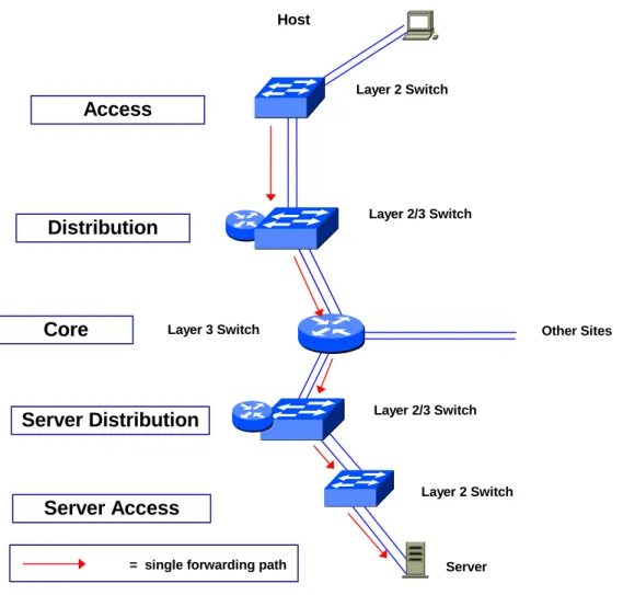
One approach to building highly available networks is to use extremely fault tolerant network devices throughout the network, as shown in Figure 1. To achieve high availability end-to-end, the fault tolerance of each device is optimized. This is achieved by providing redundant backup within the device for each of its key components. For example, a highly fault tolerant switch might be configured with redundant power supplies, cooling fans, switch fabrics, and switch processors, plus have provisions for redundant links via interfaces that support dual PHY or multi-linked connections. With this degree of internal redundancy, it is possible to achieve calculated device-level Mean Time Between Failure (MTBF) of up to 100,000 hours. Assuming a Mean Time to Repair (MTTR) of one hour, this MTBF would correspond to a theoretical device-level availability of 99.999%. While the theoretical calculations for device hardware MTBF can result in impressive numbers, trying to achieve high network availability solely through device-level fault tolerance has a number of drawbacks:
• Massive redundancy within each device adds significantly to its cost, while at the same time reducing physical capacity by consuming slots that could otherwise house network interfaces or provide useful network services.
• Redundant subsystems within devices are often maintained in a hot standby mode, where they cannot contribute additional performance because they are only fully activated when the primary component fails. • Focusing on device-level hardware reliability may result in a number of other failure mechanisms being
overlooked. Network elements are not stand-alone devices, but are components of a network system whose internal operations and system-level interactions are governed by software and configuration parameters. Each component of the network system also resides in a physical environment that requires electrical power, environmental control, and human operators. Imperfections in any of these “softer” aspects of the network has the potential to cause failures that cannot be offset solely through device-level hardware redundancy.
Accordingly, if a production network is designed with highly fault tolerant devices, but with multiple single points of failure as shown in Figure 1, the soft failure mechanisms are likely to be the dominant causes of network
downtime, completely masking the reliability of the hardware. Each failure that does occur will require human intervention for diagnosis and repair, resulting in a typical downtime (or Mean Time To Repair) of 2-4 hours. Thus, with single points of failure in the network design, the additional economic burden of highly fault tolerant devices may produce little measurable benefit in terms of the overall network system availability actually observed.
Host
Layer 3 Switch
Server Layer 2 Switch
Layer 2/3 Switch
= single forwarding path
Layer 2/3 Switch Layer 2 Switch
Access
Distribution
Core
Server Distribution
Server Access
Other SitesFigure 1: Campus Network with Fault Tolerant Devices and Single Points of Failure
Networks with Redundant Topologies
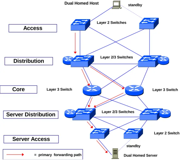
Another way to build highly available networks is to provide most of the reliability through redundancy in the network topology rather than primarily within the network devices themselves. With this design approach, The campus LAN shown in Figure 1 would be modified as shown in Figure 2. In this network, there a backup for every link and every network device in the path between the client and server. This approach to network reliability has a number of potential advantages.
• The network elements providing redundancy need not be co-located with the primary network elements. This reduces the probability that problems with the physical environment will interrupt service.
• Problems with software bugs/upgrades or configuration errors/changes can often be dealt with separately in the primary and secondary forwarding paths without completely interrupting service. Therefore,
• With the redundancy provided by the network, each network device no longer needs to configured for the ultimate in standalone fault tolerance. Device-level fault tolerance can be concentrated in the Core and Distribution Layers of the network where a hardware failure would be expected to affect a larger number of users. By partially relaxing the requirements for device-level fault tolerance, the cost per network device is reduced, to some degree offsetting the requirement for more devices
• With appropriate resiliency features, plus careful design and configuration, the traffic load between the respective layers of the network topology (e.g., Access Layer to Distribution Layer) can be shared between the primary and secondary forwarding paths. Therefore, network-level redundancy can also provide increased aggregate performance and capacity, which in turn helps to reduce the incremental cost of a redundant network.
• Redundant networks can be configured to automatically fail-over from primary to secondary facilities without operator intervention. The duration of service interruption is equal to the time it takes for fail-over to occur. Fail-over times as low as a few seconds are possible.
Dual Homed Host
Layer 3 Switch
Dual Homed Server Layer 2 Switches
Layer 2/3 Switches
Layer 3 Switch
= primary forwarding path
Layer 2/3 Switches Layer 2 Switch
Access
Distribution
Core
Server Distribution
Server Access
standby standbyDesigning a cost-effective network that supports business objectives for high availability of network services and communications services requires the right mix of networking technologies (including device-level fault tolerance and network-level redundancy) and complementary operational procedures. In many cases, a successful implementation of a high availability network project will include a balanced combination of the following considerations:
Definition and Measurement of Availability: A good operational definition of availability is one that matches a particular organization’s expectations of the network and can be measured fairly easily. Ideally, the availability metric would take into account the impact on users of each failure within the network. For example, a failure that makes network resources unavailable for 10 out of 1000 users should have less impact on the calculation of overall network availability than a failure affecting 100 users. Depending on the availability metric selected, service Level Management applications may be available to track network availability.
Fault Management and Diagnosis: Careful diagnosis of failures is a key prerequisite for optimizing the
availability of the network because it allows adjustments to be made in order to prevent recurrences of the same type of fault. Accurate failure diagnosis requires a well-instrumented network with good time-synchronization across the network elements to allow event correlation.
Device-level Hardware Reliability: An appropriate level of fault tolerance should be configured to keep hardware failures from making a large contribution to the total failure rate. The degree of fault tolerance within devices should be configured in proportion to the impact the hardware failure would have on the availability metric. This means that end user Access switches can generally be configured with less fault tolerance than either Distribution switches, Core switches or server Access switches. The device-level redundancy features of Cisco Catalyst switches are summarized in Appendix B.
Operational Best Practices: The non-hardware failure rate can be minimized by adopting best industry practices to reduce the frequency of other common causes of failures. Applying best practices in software version control, device configuration control, user access privileges and security, wiring closet and computer room cabling, physical plant maintenance, etc. can all contribute significant to reducing the overall failure rate. Cisco offers extensive documentation of best practices as part of its High Availability Service offering.
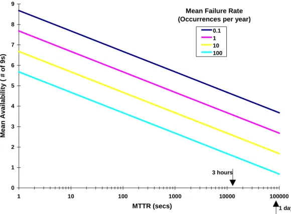
Network-level Redundancy: Configuring redundant network elements allows the operation of the network to continue in spite of a variety of hardware and non-hardware failures. Automated fail-overs can limit the average duration of service interruptions to seconds vs. the hours usually required for operator diagnosis and repair. As shown in Figure 3, the availability of a network element is improved by more than 3 “9s” if the recovery time after failure is reduced from a normal MTTR of 3 hours to a fail-over time of 10 seconds. After the fail-over, network services continue, but users may notice reduced performance until the failed element is restored to service. Restoring the failed element will often involve an brief interruption of service, usually less than or comparable to the fail-over time. As in the case of device-level redundancy, network-level redundancy can be concentrated where it will have the greatest impact on the overall availability metric.
Network Design and Tuning: Careful network design and configuration maximizes the leverage that can be derived from resiliency and availability features of switches and other network devices. Configuring protocol timers to exploit specific network configurations can reduce fail-over times by a factor of three or more. Figure 3 shows that further reductions in fail-over time can have a significant impact on device-level or system-level availability.
Load Balancing Across Redundant Network Devices: Another important aspect of exploiting network-level redundancy and resilience features is the ability to design the network so that during normal operation the primary and the secondary (redundant) data paths are sharing the traffic load as equally as possible, with a minimum number of device ports and links in an idle or standby mode. Load sharing across the redundant paths/devices can largely offset the additional cost of dual network elements and links
Server Fault Tolerance: The availability of the network system cannot exceed that of the servers used to deliver critical applications, data, and key network services. Therefore, server fault tolerance strategies, such as dual homing, clustered systems, or networked backup servers, cannot be overlooked. Ideally, the availability tracking mechanism employed would be able to distinguish between network and server failures.
0 1 2 3 4 5 6 7 8 9 1 10 100 1000 10000 100000 MTTR (secs) Me a n A v a ila b ility ( # o f 9 s ) 0.1 1 10 100
Mean Failure Rate (Occurrences per year)
3 hours
1 day
Figure 3: Device Availability vs. MTTR and Failure Rate
Network Redundancy/Resilience Features in Catalyst Switches
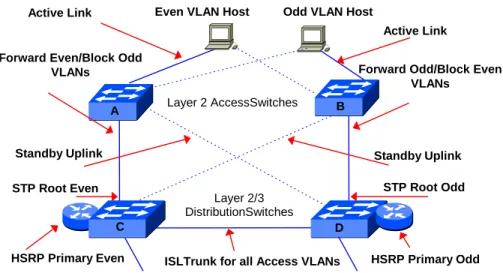
A fully redundant network design module for wiring closet (Access Level) and wiring center (Distribution Level) connectivity using Cisco switches is shown in Figure 4. The design exploits Cisco’s per-VLAN Spanning Tree (ST), Inter Switch Link (ISL) and 802.1Q VLAN trunking, UplinkFast ST, and per-VLAN Hot Standby Routing Protocol (HSRP). Each end system is dual homed using a 2-port Ethernet NIC and connected to each of the redundant wiring closet switches. In normal operation all the traffic from/to even numbered VLANs is forwarded through switches A and C, while switches B and D carry the traffic for the odd VLANs. In the event of failure of the odd VLAN primary path (end system link, Access Switch B or primary uplink from Switch B to Switch D), traffic for both the even and odd VLANs would flow through Switches A and C as required to maintain operation.
Per-VLAN Spanning Tree and ISL
Cisco’s Spanning Tree implementation provides a separate spanning tree domain for each VLAN or per-LAN Spanning tree (PVST). PVST allows the bridge control traffic to be localized within each VLAN and supports configurations where the traffic between the Access and Distribution levels of the network can be load balanced over redundant connections. Cisco supports PVST over both ISL and 802.1Q trunks. PVST is a value-added feature of Cisco’s implementation of the IEEE 802.1Q standard.
Cisco’s InterSwitch Link (ISL) or 802.1Q VLAN tagging also plays an important role in load sharing across redundant links. All of the Layer 2 interswitch links between Access and Distribution switches are configured as
VLANs may be carried by the most appropriate remaining uplink. With ISL or 802.1Q configured on the link between Distribution switches, workgroup servers on either switch may be configured as part of either odd or even VLAN subnets
The primary and secondary (redundant) paths for each VLAN are configured as follows: The uplink port on Switch C indicated in Figure 4 is designated as the Spanning Tree root for all the even numbered Access VLANs and as the secondary Spanning Tree root for all the odd numbered VLANs The primary root setting is denoted by a higher bridge priority than for a secondary root. (For historical reasons, the higher bridge priority is denoted by a lower bridge priority value). In normal operation, the port on Switch A connected to Switch D is blocked from forwarding traffic. The corresponding port on Switch D is configured similarly as the designated root bridge for the odd VLANs. In the Cisco per-VLAN ST implementation, the command that sets the root bridge includes the Spanning Tree Layer 2 network “diameter” as an argument. The ST diameter is the number of bridge hops from the root to the furthest leaf of the VLAN (e.g., the ST diameter is 2 for all the Access VLANs in Figure 4). When the root bridge is identified and set, the ST parameters (Max Age, Hello Time, Forwarding Delay), which govern the speed of ST convergence, are automatically scaled down in proportion to the ST diameter of 2 hops. Because of the automated scaling (tuning) of ST parameters, the traffic can fail-over to the redundant paths for each VLAN in much less time than if the default standard Spanning Tree parameter values were used.
Fast Spanning Tree
The Spanning Tree protocol was designed for robust, plug-and-play operation in bridged internetworks of arbitrary connectivity (looping) and almost unlimited flatness (network diameters of 7 or more bridge hops). With more disciplined, hierarchical L2/L3/L3 and L2/L3/L2 network designs, bridging (or Layer 2 switching) is relegated to well-constrained, small network-diameter applications, such as in the wiring closet and data center as shown in Figure 4. Accordingly, Cisco has developed a set of features that exploit the topological constraints of the
Access/Distribution/Core Model in order to further accelerate Spanning Tree convergence and thereby reduce the fail-over time in redundantly configured networks.
With the failure of a directly connected uplink connecting an Access switch to a Distribution switch (e.g., Switch A to Switch C in Figure 4), the speed of ST convergence can be increased by enabling the UplinkFast feature on the Access switch. With UplinkFast, each VLAN is configured with an Uplink Group of ports, including the root port that is the primary forwarding path to the designated root bridge of the VLAN and one or more secondary ports that are blocked. When a direct uplink fails, UplinkFast unblocks the highest priority secondary link (in this case, the link from Switch A to Switch D) and begins forwarding traffic without going through the Spanning Tree listening and learning states. Bypassing listening and learning reduces the fail-over time after uplink failure to approximately the Bridge Protocol Data Unit (BPDU) hello interval (1-5 seconds). With the default configuration of standard Spanning Tree, reconvergence after uplink failure can take up to 30 seconds.
The BackboneFast feature accelerates Spanning Tree convergence after the failure of non-directly connected (indirect) network links. Under normal Spanning Tree operation, when a switch is notified of an indirect link failure, it waits for it forwarding table to age out before beginning the process of listening and learning to determine the new topology. With BackboneFast, the switch immediately proceeds to listening/learning on its blocked ports without waiting for the Max Age timer to expire, reducing the convergence time by the Max Age setting (typically up to 20 seconds). BackboneFast is normally enabled on all Access and Distribution switches in configurations such shown in Figure 4.
PortFast is another feature of Cisco’s Fast Spanning Tree that can be enabled on Catalyst switch ports dedicated to connecting single servers or workstations. PortFast allows the switch port to begin forwarding as soon the end system is connected, again bypassing the listening and learning states and eliminating up to 30 seconds of delay before the end system can begin sending and receiving traffic. PortFast comes into play when an end system is initially connected to the network or when the primary link of a dual-homed end system or server is reactivated after a fail-over to the secondary link. Since only one station is connected to the segment, there is no risk of PortFast creating network loops.
Layer 2 AccessSwitches
Layer 2/3 DistributionSwitches Forward Even/Block Odd
VLANs Forward Odd/Block Even
VLANs
STP Root Even STP Root Odd
HSRP Primary Even ISLTrunk for all Access VLANs HSRP Primary Odd Even VLAN Host Odd VLAN Host
Standby Uplink Standby Uplink A B C D Active Link Active Link
Figure 4: Cisco Redundancy/Resilience in the Access and Distribution Layers of the Network
Hot Standby Routing Protocol
In Figure 4, the Layer2/Layer3 Distribution switches (Switches C and D) provide redundant routed connections to the Layer 3 Core. With the Cisco Hot Standby Routing Protocol (HSRP) configured on each switch, Switches C and D can be configured respectively as the primary paths to the Core for the even and odd VLANs, and as the secondary paths for odd and even VLANs. In this way, each Distribution switch plays a consistent role at both Layer 2 and Layer 3 -–the primary path for one half of the VLANs and the secondary path for the other half. HSRP creates a virtual router interface that can be shared by two or more routers. The interface consists of a virtual MAC address drawn from a pool of addresses reserved for Cisco devices and a virtual IP address. HSRP is configured on a per-VLAN basis and members of each VLAN are configured with the HSRP virtual interface as the default gateway. Each of the routers participating in the virtual interface is assigned a priority that determines which is the primary router. Within each VLAN the HSRP routers multicast periodic “hello” messages that include the priority of the sending router. In the event the primary router fails, the secondary router detects the missing hello, determines that it has the highest remaining priority, and begins processing the traffic addressed to the virtual interface.
HSRP also has a feature which allows the HSRP router priority to “track” the status of its key interfaces to the Core. When tracking is enabled and a tracked interface becomes unavailable, the HSRP priority of the router is automatically decremented. For example, if a HSRP switch router (such as Switch C in Figure 4) loses all its interfaces to the Core, the decrements can be configured so that it will relinquish its status as the primary (or active) router for the even VLANs. As Switch D then becomes the active HSRP router for the even (as well as the odd) VLANs, the even VLAN traffic flows directly to Switch D without unnecessarily traversing the extra Switch C router hop. The track extension to HSRP provides the network engineer with the ability to pre-determine how the network will be reconfigured in the event of anticipated failures. This can help ensure that consistent services will be maintained and performance will be optimized while redundancy is being restored.
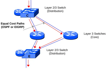
Layer 3 Redundancy and Load Balancing
Layer 3 networks based on EIGRP and OSPF can be designed to provide load balancing across multiple parallel physical paths. EIGRP is a fast converging, enhanced distance vector routing protocol that supports load sharing across multiple paths, even it the paths have different route metric values. OSPF is a fast converging, shortest path first routing protocol that can load balance across multiple equal cost paths. In Figure 5, the even VLAN traffic is load balanced across the parallel Core paths between the Distribution Switches C and E.
In order to demonstrate the effectiveness of the Catalyst network availability features described in the previous section of this report, Cisco invited the authors to observe a comprehensive demonstration of the fast fail-over times that can be achieved when the various elements throughout the Access/Distribution/Core Layers of a highly redundant test network are caused to fail.
The demonstration network shown in Figure 6 was configured in one of Cisco’s Enterprise Solution Center labs in San Jose, California. The entire network was provisioned with Fast Ethernet and Gigabit Ethernet links. Gigabit Ethernet was used for the Access/Distribution interswitch links, while Fast Ethernet was used in the Core Layer and for end system connections. The network transit times for all link speeds are negligible compared to the fail-over times, so link speed should have had no bearing on the observed results.
Layer 2/3 Switch (Distribution) Equal Cost Paths
(OSPF or EIGRP) Layer 3 Switches (Core) Layer 2/3 Switch (Distribution) C E
Figure 5: Cisco Redundancy/Resilience in the Core Layer
Network Redundancy/Resilience Demonstration
In order to demonstrate the effectiveness of the Catalyst load balancing network reliability and resiliency features described in the sidebar, Cisco invited the authors to observe a comprehensive demonstration of the fast fail-over times (i.e., Mean Time to Recover) that can be achieved when various elements throughout the
Access/Distribution/Core Layers of a highly redundant test network are caused to fail.
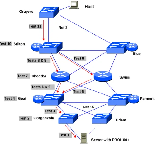
The demonstration network shown in Figure 6 was configured in one of Cisco’s Enterprise Solution Center labs in San Jose, California. The entire network was provisioned with Fast Ethernet and Gigabit Ethernet links. Gigabit Ethernet was used for the Access/ Distribution interswitch links, while Fast Ethernet was used in the Core Layer and for end system connections. The network transit times for all link speeds are negligible compared to the fail-over times, so link speed should have no bearing on the observed results.
Host Net 2 Net 15 Gruyere Stilton Blue Cheddar Swiss Goat Gorgonzola Edam Farmers
Server with PRO/100+ Test 2 Test 1 Test 3 Test 4 Tests 5 & 6 Test 6 Test 7 Test 9 Tests 8 & 9 Test 10 Test 11
Figure 6: Network Configuration for Resilience Demonstration
In order to demonstrate the consistency of IOS availability/resiliency features across the Catalyst family of switches, the network was configured with a mixture of Catalyst 5000 and Catalyst 4003 switches in the Access Layer, Catalyst 5500 and Catalyst 5000 switches with Route Switch Modules in the Distribution Layer, and Catalyst 8510 switches in the Core Layer. The Core routing protocol was chosen to be OSPF, but EIGRP could also have been used with quite similar results. The details of the switch models and software versions used in the test are included in Appendix A.
The client host was configured to continually ping the server at the rate of 1 ping per second. With the pings free running, each of the elements in the primary path from the dual-homed server to the Gruyere Access switch was caused to fail, while the network fail-over time was observed by counting the number of failed pings. Because the fail-over times are based on various software timing mechanisms and hello intervals, some variability was observed between repeated trials of the same test. The results that are presented below are average fail-over times over a number of trials with each measurement’s accuracy being approximately +/- one second.
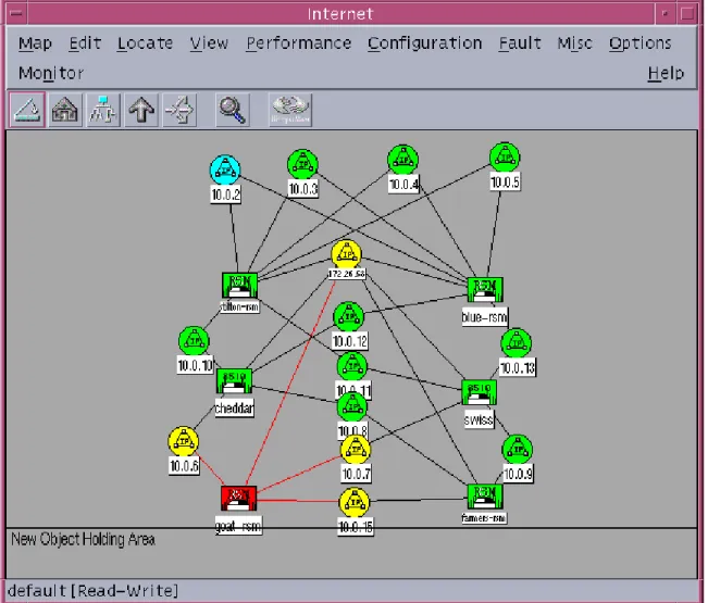
In order to maximize the visibility of the fail-over processes, the demonstration network was fully instrumented with Cisco Network Management solutions. These included: CWSI Campus for monitoring Layer 2 topology and device configuration, Cisco Resource Manager Essentials for Syslog Analysis and Availability monitoring, HP OpenView for Layer 3 topology and high-level event management and Internetwork Performance Monitor (IPM) for availability troubleshooting and detecting ping failures. (see Figures C1 and C2 in Appendix C for the HP OpenView Layer 3 topology view of the demo network and typical IPM diagnostic screen.) With these tools
diagnose failure causes in Cisco switched internetworks.
The elements of the demonstration network were synchronized with Network Time Protocol (NTP) services to allow accurate event correlation between the HP OpenView Event Monitor and the Essentials Syslog Analyzer. The Syslog Analyzer allows syslog messages from IOS routers and switches to be filtered, making it easier to highlight critical error messages. It also provides explanations of the probable causes of error messages and recommends corrective actions. Additionally, the Syslog Analyzer can launch user-defined Common Gateway Interface (CGI) scripts to automate selected corrective actions.
The remaining application modules within Essentials (Inventory Manager, Configuration Manager, Software Image Manager, and the Availability Manager) can also play important roles in assuring high availability of the network. Inventory Manager allows the history of hardware and software changes to be logged. Configuration Manager tracks device configuration changes throughout the network. Tracking such changes (and the operator who made them) is a critical aspect of implementing best practices to minimize operational errors in configuration and software version management. The Software Image Manager also supports best practices in keeping software versions consistent and up-to-date by checking device prerequisites for a proposed image upgrade, flagging devices that are not compatible with the new version, and subsequently downloading the new software under operator supervision. The Availability Manager uses standard polling techniques to track the reachability and response time of Cisco routers and switches. This allows the network manager to conveniently monitor the availability and status of the entire network or a specific group of critical devices, as illustrated in Figure C3 in Appendix C.
Network Redunancy/Resilience Test Results
Test 1: Failure of Server Link
In this test, the primary link from the dual-homed server to the Gorgonzola Access switch was removed causing the fail-over to the secondary server link to the Edam Access switch (see Figure 6). The Server was equipped with an Intel PRO/100+ dual port 10/100 Ethernet PCI bus NIC configured in Adapter Fault Tolerant (AFT) mode. (If more server-to-switch throughput had been desired, up to four Intel PRO/100+ adapters could have been configured to a achieve a fault tolerant Fast EtherChannel connection with 400 Mbps of bandwidth for both the primary and secondary connections.) The fail-over time between the PRO/100+ primary and secondary ports is determined by the inter-port polling interval configured on the NIC, which had been set to two seconds for this demonstration. The interswitch link between Edam and Goat was already an active link for the server’s VLAN, so Edam was able to forward server traffic as soon as the secondary NIC port became active. The observed network fail-over time was two seconds.
Test 2: Failure of Primary Access Switch
In the next test, the failure of Gorgonzola Access switch was simulated by removing its power connection. The fail-over process is identical to that in Test 1, and the same network fail-over time of two seconds was observed. Although it was not tested, the same fail-over behavior and recovery time could be expected to apply in case of a failed interface module on the primary Access switch or failure of the primary port of the dual port NIC.
Test 3: Failure of Access Switch Primary Uplink
In this test, the uplink between the Gorgonzola Access switch and the Goat Distribution switch was removed to simulate its failure. With this failure, the blocked path from Gorgonzola to Farmers must be made the active path, with the traffic subsequently being forwarded from Farmers to Goat over the ISL link between these switches. With UplinkFast enabled on the Access switches, the path from Gorgonzola to Farmers had been pre-selected by spanning tree to be the secondary path of the uplink group, and the failover to the secondary link occurred as soon as a break in physical connectivity was detected on the primary link. The observed network fail-over time
was 2 seconds. With normal Spanning Tree and default parameter values this fail-over could take as long as 30 seconds.
Test 4: Failure of Distribution Switch
Next, the failure of the Goat Layer2/Layer3 switch was simulated by removing its power connection. In this scenario several separate fail-overs had to occur before service was recovered: the traffic flowing through Gorgonzola had to be diverted via UplinkFast to Farmers as in Test 3, Spanning Tree for the server’s VLAN had to reconverge, the Farmers Route Switch Module (RSM) had to also become the active HSRP router for the server’s VLAN, and therefore OSPF converged to activate the Layer 3 path from Farmers to the Cheddar Core switch. In the configuration of the demonstration network, the HSRP standby timers had been set to less than one second, and the OSPF hello-interval and dead-interval had been set to one and three seconds respectively. With this configuration, the observed network recovery time, comprised of the total time for all of these fail-overs to occur, was 9-10 seconds.
Test 5: Failure of a Single Link from Distribution Switch to Core
In this test, the Layer 3 link between the Goat Distribution switch and the Cheddar Core switch was removed to simulate its failure. Prior to this failure the Layer 3 core had been configured for load balancing across the two equal cost paths indicated in Figure 6. Since load balancing was performed on a per-destination basis, all of the server-to-host traffic was flowing over the failed Layer 3 link. With load balancing configured, the traffic could immediately continue to traverse the Core via the Swiss Layer 3 switch since there is no need for convergence. At the resolution of the time measurement mechanism employed, the recovery time from this failure was observed as instantaneous --a fail-over time of zero seconds.
Test 6: Failure of Both Links from Distribution Switch to Core
Next, both the uplinks from Goat to the Core were simultaneously removed. In this failure scenario Goat retains a path to the Core via its Layer 2 link to Farmers. Therefore, it would be possible for Goat to remain the primary HSRP router for the server VLAN, but this would involve an unnecessary extra routed hop because the traffic could flow directly to Farmers and then to the Core. The HSRP Tracking feature was designed expressly to prevent this sort of sub optimal routing. For the demonstration network, HSRP Tracking had been configured so that Goat’s standby priority would be decremented in the event of failure of uplinks to the Core. The decrement in priority had been chosen in such a way that if only one uplink failed (as in Test 5), Goat would remain the HSRP primary, but if both uplinks failed, Goat’s priority would fall below the priority of the secondary HSRP router (the Farmers RSM). With Farmers assuming the role of primary router to the Core, the total fail-over time is
determined by HSRP standby timers and OSPF timers, as in Test 4. The observed fail-over time for the test was 6-8 seconds.
Test 7: Failure of Core Switch
This test simulated the failure of the Cheddar Core switch. The fail-over mechanism and results are essentially the same as in Test 5.
Additional Testing
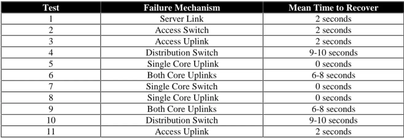
Additional failures were simulated in the host side of the Core, Distribution, and Access network model as indicated by the test numbers 8-11 in Figure 6. The test descriptions and results for these tests are the same as the corresponding tests in the server side of the Core, Distribution, and Access model, so they are not repeated here. The results for all the tests are summarized in Table 1.
Test Failure Mechanism Mean Time to Recover
1 Server Link 2 seconds
2 Access Switch 2 seconds
3 Access Uplink 2 seconds
4 Distribution Switch 9-10 seconds
5 Single Core Uplink 0 seconds
6 Both Core Uplinks 6-8 seconds
7 Single Core Switch 0 seconds
8 Single Core Uplink 0 seconds
9 Both Core Uplinks 6-8 seconds
10 Distribution Switch 9-10 seconds
11 Access Uplink 2 seconds
Table 1: Summary of Test Results
Conclusions
The resiliency and availability features supported by the Cisco Catalyst family of switches are well-suited to campus LAN designs that achieve high availability through a combination of device-level and network-level redundancy. The network resiliency features span Layer 2 and Layer 3 boundaries and may be deployed where they are needed throughout the Cisco three-tiered Access/Distribution/Core design model.
With some care in configuring the redundant network and tuning the protocol timers within the switches, interruption of network services due to network infrastructure failures can held in the range of 0 to 10 seconds. With these short fail-over times, very high network availability can be achieved by controlling the overall network failure rate (λ). λ can be minimized by configuring an appropriate degree of device-level redundancy to increase hardware Mean Time Between Failures (MTBF) and by adhering to a comprehensive set of best practices in fault management, software version control, device configuration control, user access privileges and security, wiring closet and computer room cabling, and physical plant maintenance. Cisco has drawn on its wide experience in building large networks to develop an extensive set of documentation on best practices. This documentation is offered as part of the Cisco High Availability Service (HAS).
The degree of load sharing that can be achieved in the Cisco high availability network design significantly reduces the cost burden of provisioning full redundancy and makes fault tolerance a more attractive design feature. With a given level of performance distributed across primary and secondary devices, the redundant network may involve a relatively modest cost increment over a non-redundant network. The additional cost of redundancy depends on specific characteristics of the network, but the cost increment can generally be expected to be inversely
proportional to both the size of the network Core and to the degree of over-subscription that is employed between the Access and Distribution layers.
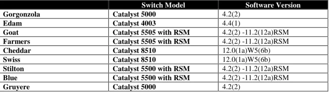
Appendix A: Demonstration Network Configurations
Switch Model Software Version
Gorgonzola Catalyst 5000 4.2(2)
Edam Catalyst 4003 4.4(1)
Goat Catalyst 5505 with RSM 4.2(2) -11.2(12a)RSM
Farmers Catalyst 5505 with RSM 4.2(2) -11.2(12a)RSM
Cheddar Catalyst 8510 12.0(1a)W5(6b)
Swiss Catalyst 8510 12.0(1a)W5(6b)
Stilton Catalyst 5500 with RSM 4.2(2) -11.2(12a)RSM
Blue Catalyst 5500 with RSM 4.2(2) -11.2(12a)RSM
Gruyere Catalyst 5000 4.2(2)
Appendix B: Device-Level Redundancy Features of Catalyst Switches
Redundancy Features
Catalyst 4000 Dual Power Catalyst 5000 Dual Power Catalyst 5505 Dual Power Catalyst 5509 Dual Power, Dual SEM Catalyst 6000 Dual Power, Dual SEM
Catalyst 6500 Dual Power, Dual SEM, Redundant Switch fabric
Catalyst 8510 Dual Power
Catalyst 8540 Dual Power, Dual SEM, Redundant Switch fabric, Redundant L3 Engine