A Grid Connected Wind Energy System’s Power Quality Improvement By
Using D-Statcom
M.Somi Reddy, V.Srinivasa Rao
1M.Tech Scholar, Aditya Engineering College, Surampalem 2
Associate
Professor, EEEAditya Engineering College, Surampalem
ABSTRACT
:
Now a day’s one of the Main issue is Power Quality. The modern device performance is very sensitive with the power supply quality and makes it’s an important aspect. Power Quality problem occurs when the voltage, current and frequency become nonstandard and end use equipment gets damage. The harmonics, compensation of reactive power and power factor is a main problem dealt here. According to the guideline specified in International Electro-technical Commission standard, IEC-61400, by the measurements and norms specified can determine the performance there by power quality of a wind turbine. The active power, reactive power, voltage changes, flicker, harmonics, electrical behavior of switching operation are the concerning power quality measurements by the effect of the wind turbine in the grid system. These quantities are measured based on national/international guidelines. The power electronic switching devices such as Flexible AC Transmission System (FACTS) have been developed; introduction of customs power devices and the technology of emerging branch provide a modern control capability of power system. The paper study describes how the wind turbine installation creates power quality problem in grid system. In the proposed system in order to solve the power quality issues a battery energy storage system (BESS) connected by STATIC COMPENSATOR (STATCOM) at a common point coupling. The real power source under fluctuating wind power is sustained by the integrated battery energy storage. For the power quality improvement of a grid connected wind energy generation system a STATCOM control scheme is simulated using MATLAB /SIMULINK in power system block set. Finally the proposed scheme is applied to a balanced linear load, unbalanced liner load, balanced non linear load and unbalanced non linear load.
KEYWORDS:
International electro-technical commission (IEC), power quality, wind generating system (WGS),
D-Statcom (Distributed Static Synchronous Compensator).
I.INTRODUCTION
The Industrial, domestic and commercial applications are very widely using power electronic device based converters. Hence these applications are facing a problem to receive non sinusoidal current and reactive power from the supply system. The other loads connected at the same point of common coupling (PCC) are gets affected by the voltage distortion caused by this behavior. In the recent years of power engineering the term power quality has captured increasing attention. The quality of power measure depends upon equipment needs being supplied. The good power quality may not same for an electric motor and a personal computer.
The term power quality is nothing but maintaining a sinusoidal rated bus voltages and frequency waveforms [1]. Actually the voltage produced on the generation is a pure sinusoidal with no distortion. The voltage sags, harmonic distortion and low power factor are the most severe problems of power quality. A short event occurred in between 10ms to 1 min that cause magnitude of RMS voltage reduction is called as voltage sag [1]. It usually set by two parameters those are magnitude and duration. The magnitude of voltage sag is in between 10% to 90% of nominal value during an interval of half cycle to 1min.
frequently and causes economic loss. The utilities mainly concentrate on the main power quality problem of disturbances from end user equipment. Voltage sags are more severe in High voltage levels.Faults due to lightning, is one of the most common causes to voltage dips on overhead lines. If the economical losses due to voltage dips are significant, mitigation actions can be profitable for the customer and even in some cases for the utility. Since there is no standard solution which will work for every site, each mitigation action must be carefully planned and evaluated. There are different ways to enhance power quality problems in transmission and distribution systems. Among these, the D-STATCOM is one of the most effective devices.
A new PWM based control scheme has been implemented to control the electronic valves in the DSTATCOM. The D-STATCOM has additional capability to sustain reactive current at low voltage, and can be developed as a voltage and frequency support by replacing capacitors with batteries as energy storage. STATCOM is often used in transmission system. When it is used in distribution system, it is called D-STATCOM _ STATCOM in Distribution system. D-STATCOM is a key FACTS controller and it utilizes power electronics to solve many power quality problems commonly faced by distribution systems.
Potential applications of D-STATCOM include power factor correction, voltage regulation, load balancing and harmonic reduction. Comparing with the SVC, the D-STATCOM has quicker response time and compact structure.
It is expected that the D-STATCOM will replace the roles of SVC in nearly future D-STATCOM and STATCOM are different in both structure and function, while the choice of control strategy is related to the main-circuit structure and main function of compensators [8], so D-STATCOM and STATCOM adopt different control strategy. At present, the use of STATCOM is wide and its strategy is mature, while the introduction of D-STATCOM is seldom reported. Many control techniques are reported such as instantaneous reactive power theory (Akagi et al., 1984), power balance theory, etc.
In this paper, an indirect current control technique (Singh et al., 2000a,b) is employed to obtain gating signals for the Insulated Gate Bipolar Transistor (IGBT) devices used in current controlled voltage source inverter (CC-VSI) working as a DSTATCOM. A model of DSTATCOM is developed using MATLAB for investigating the transient analysis of distribution system under
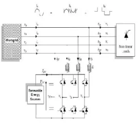
balanced/ unbalanced linear and non-linear three-phase and singlethree-phase loads (diode rectifier with R and R-C load). Simulation results during steady-state and transient operating conditions of the DSTATCOM are presented and discussed to demonstrate power factor correction, harmonic elimination and load balancing capabilities of the DSTATCOM system [5-10]. A possible solution to overcome the above mentioned drawback is to use the DSTATCOM as a power interface between the renewable energy sources and the AC bus of the microgrids as shown in Fig. 1. The DSTATCOM has proved to be an important alternative to compensate
current and voltage disturbances in power distribution systems [2,3]. Different DSTATCOM topologies have been presented in the technical literature [4], but most of them are not adapted for microgrids applications.
Fig.1. DSTTACOM for Microgrid Application
2. Distribution Static Compensator (DSTATCOM)
A. Principle of DSTATCOM
Fig. 2 DSTATCOM Main Circuit It consists of a three-leg four-wire voltage source inverter. In this type of applications, the VSI operates as a current controlled voltage source. In order to provide the neutral point, two capacitors are used to split the DC-link voltage and tie the neutral point to the mid-point of the two capacitors. This topology allows the current to flow in both directions through the switches and the capacitors, causing voltage deviation between the DC capacitors. The VSC connected in shunt with the ac system provides a multifunctional topology which can be used for up to three quite distinct purposes: 1. Voltage regulation and compensation of reactive power;
2. Correction of power factor; and 3. Elimination of current harmonics.
B. Voltage Source Converter (VSC)
A voltage-source converter is a power electronic device that connected in shunt or parallel to the system. It can generate a sinusoidal voltage with any required magnitude, frequency and phase angle. The VSC used to either completely replace the voltage or to inject the ‘missing voltage’. The ‘missing voltage’ is the difference between the nominal voltage and the actual. It also converts the DC voltage across storage devices into a set of three phase AC output voltages [8, 9]. In addition, APC is also capable to generate or absorbs reactive power. If the output voltage of the VSC is greater than AC bus terminal voltages, APC is said to be in capacitive mode. So, it will compensate the reactive power through AC system and regulates missing voltages. These voltages are in phase and coupled with the AC system through the reactance of coupling transformers. Suitable adjustment of the phase and magnitude of the APC output voltages allows effectives control of active and reactive power exchanges between APC and AC system. In addition, the converter is normally based
on some kind of energy storage, which will supply the converter with a DC voltage [10].
C. Controller for DSTATCOM
The three-phase reference source currents are computed using three-phase AC voltages (vta,vtb and vtc) and DC bus voltage (Vdc) of DSTATCOM. These reference supply currents consist of two components, one in-phase (Ispdr) and another in quadrature (Ispqr) with the supply voltages. The control scheme is represented in Fig. 3. The basic equations of control algorithm of DSTATCOM are as follows.
D. Computation of in-phase components of reference supply current
The instantaneous values of in-phase component of reference supply currents (Ispdr) is computed using one PI controller over the average value of DC bus voltage of the DSTATCOM (vdc) and reference DC voltage (vdcr) as
Ispdr= Ispdr+ Kpd{Vde(n)-Vde(n-1)}+KidVde(n)
where Vde(n) KKVdcc-Vdcn) denotes the error in Vdcc and average value of Vdc Kpd and Kid are proportional and integral gains of the DC bus voltage PI controller. The output of this PI controller (Ispdr) is taken as amplitude of in-phase component of the reference supply currents. Three-phase in-Three-phase components of the reference supply currents (isadr,isbdr andiscdr) are computed using the in-phase unit current vectors (ua, ub and uc) derived from the AC terminal voltages (vtan, vtbn andvtcn), respectively.
Ua=Vta/Vtm Ub=Vtb/Vtm Uc=Vtc/Vtm
whereVtm is amplitude of the supply voltage and it is computed as
Vtm=√[(2/3)(V2tan+ V2tbn+ V2tcn)]
The instantaneous values of in-phase component of reference supply currents (isadr, isbdr and iscdr) are computed as
Isadr=IspdsUaIsbdr=IspdrUbIscdr=IspdrUc
E. Computation of quadrature components of reference supply current
The amplitude of quadrature component of reference supply currents is computed using a second PI controller over the amplitude of supply voltage (vtm) and its reference value (vtmr)
Ispqr(n)=Ispqr(n-1)+Kpq{Vac(n)–Vac(n-1)}
+KiqVac(n)
Wa={-Ub+Uc}/{√3}
Wb={Ua√3+Ub-Uc}/{2√3}
Wc={-Ua√3+Ub-Uc}/{2√3}
Three-phase quadrature components of the reference supply currents (isaqr, isbqr and iscqr) are computed using the output of second PI controller (Ispqr) and quadrature unit current vectors (wa,wb andwc ) as
isaqr=ispqrWa, isbqr=ispqrWb, iscqr=ispqrWc
Fig. 3. Control method for DTSATCOM F. Computation of total reference supply currents
Three-phase instantaneous reference supply currents (isar, isbr and iscr) are computed by adding in-phase (isadr, isbdr and iscdr) and quadrature components of supply currents (isaqr, isbqr andiscqr) as
isar=isadr+isaqr,isbr=isbdr+isbqr,iscr=iscdr+iscqr
A hysteresis pulse width modulated (PWM) current controller is employed over the reference (isar,isbr and iscr) and sensed supply currents (isa, isb and isc) to generate gating pulses for IGBTs of DSTATCOM.
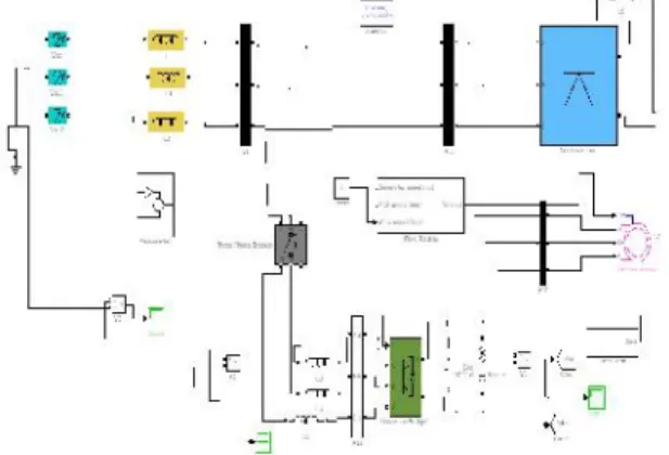
3. Matab/Simulink Modeling of DSTATCOM 3.1 Modeling of Power Circuit
Fig. 4. Matlab/Simulink Model of DSTATCOM Power
Fig.4. shows the complete MATLAB model of DSTATCOM along with control circuit. The power circuit as well as control system are modelled using Power System Blockset and Simulink. The grid source is represented by three-phase AC source. Three-phase AC loads are connected at the load end. DSTATCOM is connected in shunt and it consists of PWM
voltage source inverter circuit and a DC capacitor connected at its DC bus. An IGBT-based PWM inverter is implemented using Universal bridge block from Power Electronics subset of PSB. Snubber circuits are connected in parallel with each IGBT for protection. Simulation of DSTATCOM system is carried out for linear and non-linear loads. The linear load on the system is modelled using the block three-phase parallel R-L load connected in delta configuration. The non-linear load on the system is modelled using R and R-C circuits connected at output of the diode rectifier. Provision is made to connect loads in parallel so that the effect of sudden load addition and removal is studied. The feeder connected from the
three-phase source to load is modelled using appropriate values of resistive and inductive components.
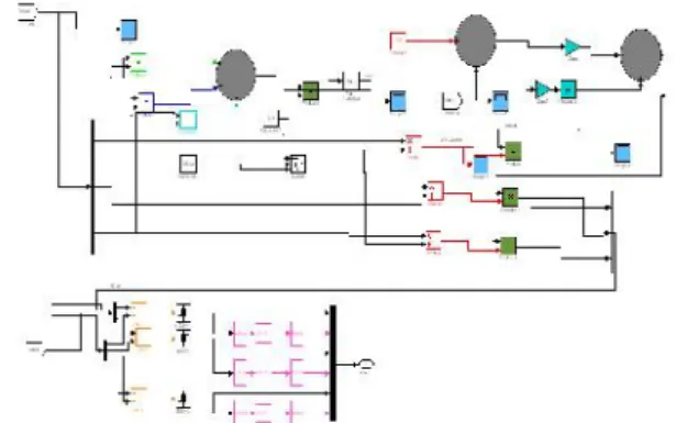
3.2 Modeling of Control Circuit
Fig.5. Control Circuit
The output of PI controller over the DC bus voltage (Ispdr) is considered as the amplitude of the in-phase component of supply reference currents and the output of PI controller over AC terminal voltage (Ispqr) is considered as the amplitude of the quadrature component of supply reference currents. The instantaneous reference currents (isar,isbr and iscr) are obtained by adding the in-phase supply reference currents (isadr, isbdr and iscdr) and quadrature supply reference currents (isaqr, isbqr and iscqr). Once the reference supply currents are generated, a carrierless hysteresis PWM controller is employed over the sensed supply currents (isa, isb
and isc) and instantaneous reference currents (isar, isbr and iscr) to generate gating pulses to the IGBTs of DSTATCOM. The controller controls the DSTATCOM currents to maintain supply currents in a band around the desired reference current values. The hysteresis controller generates appropriate switching pulses for six IGBTs of the VSI working as DSTATCOM.
4. SIMULATION RESULTS
Here Simulation results are presented for four cases. In case one load is balanced non linear, case two load is unbalanced non linear, case three load is balanced non linear load without battery connected APC and in case four load is balanced non linear with battery connected APC.
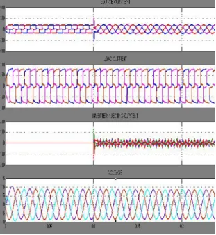
4.1 Case one: Load is Balanced Non Linear Type
Performance of DSTATCOM connected to a weak supply system is shown in Fig.6 for power factor correction and load balancing. This figure shows variation of performance variables such as supply voltages (vsa, vsb and vsc), terminal voltages at PCC (vta,vtb andvtc), supply currents (isa,isb and isc), load currents (ila, ilb and ilc), DSTATCOM currents (ica, icb and icc) and DC link voltage (Vdc).
Fig.6. Simulation results for Balanced Non Linear Load
(a) Source current. (b) Load current. (c) Inverter injected current.
Fig. 6 shows the source current, load current and compensator current and induction generator currents plots respectively. Here compensator is turned on at 0.1 seconds.
Fig.7. Simulation results power factor for Non linear Load
Fig. 7 show the power factor it is clear from the figure after compensation power factor is unity.
4.2 Case two: Load is Un- Balanced Non Linear Type
Figure. 8 Simulation results Non- Linear Unbalanced Load
Fig.8 shows the unbalanced non linear load case. From the figure it is clear that even though load is unbalanced source currents are balanced and sinusoidal.
4.3 Case Three: Balanced Non Linear load without battery connected Dstatcom
Performance of APC connected to a weak supply system, for power factor correction and load balanced and the system is connected without battery source. This figure shows variation of performance variables such as supply voltages (vsa, vsb andvsc), terminal voltages at PCC (vta,vtb and vtc), supply currents (isa,isb andisc), load currents (ila,ilb andilc), APC currents (ica,icb andicc) and DC link voltage (Vdc).
Figure. 9 Simulation results for Balanced Non Linear Load Without battery connection
( a) Source current. (b) Load current. (c) Inverter injected current.
(d) Voltage.
Fig. 9 shows the source current, load current and compensator current and induction generator currents plots respectively. Here compensator is turned on at 0.1 seconds.
Fig. 10 Simulation results power factor for Non linear Load
Fig. 10 show the power factor it is clear from the figure after compensation power factor is unity.
Fig. 11. System Active Power Measurement
Fig. 12. System Reactive Power Measurement
4.4 Case Four: Balanced Non Linear load with battery connected Dstatcom
Performance of APC connected to a supply system for power factor correction and load balanced and the system is connected with battery source. The transient responses of distribution system with APC for supply voltages (vsabc), supply currents (isabc), load currents (ila, ilb and ilc), APC currents (ica, icb andicc) along with DC link voltage (Vdc) and its reference value (Vdcr) at rectifier nonlinear load.
Fig.13. Simulation results for Balanced Non Linear Load With battery connection ( a) Source current. (b) Load current. (c) Inverter
injected current. (d) Voltage
Fig.14. System Active and Reactive Power Measurement
5. CONCLUSION
DSTATCOM system is an efficient mean for mitigation of PQ disturbances introduced to the grid by DERs. DSTATCOM compensator is a flexible device which can operate in current control mode for compensating voltage variation, unbalance and reactive power and in voltage control mode as a voltage stabilizer. The latter feature enables its application for compensation of dips coming from the supplying network. The simulation results show that the performance of
DSTATCOM system has been found to be satisfactory for improving the power quality at the consumer premises. DSTATCOM control algorithm is flexible and it has been observed to be capable of correcting power factor to unity, eliminate harmonics in supply currents and provide load balancing.
It is also able to regulate voltage at PCC. The control algorithm of DSTATCOM has an inherent property to provide a self-supporting DC bus of DSTATCOM. It has been found that the DSTATCOM system reduces THD in the supply currents for linear loads. Rectifier-based non-linear loads generated harmonics are eliminated by DSTATCOM. When single-phase rectifier loads are connected, DSTATCOM currents balance these unbalanced load currents.
REFERENCES
[1] Hammad AE. Comparing the Voltage source capability of Present and future Var Compensation Techniques in Transmission System. IEEE Trans, on Power Delivery 1995; 1(1).
[2] Yalienkaya G, Bollen MHJ, Crossley PA. Characterization of Voltage Sags in Industrial Distribution System. IEEE transactions on industry applications 1999; 34(4): 682-688.
[3] Haque MH. Compensation Of Distribution Systems Voltage sags by DVR and DSTATCOM. Power Tech Proceedings, IEEE Porto, 2001; 1: 10-13.
[4] Anaya-Lara O, Acha E. Modeling and Analysis Of Custom Power Systems by PSCAD/EMTDC. IEEE Transactions on Power Delivery 2002; 17: 266-272.
[5] Bollen MHJ. Voltage sags in Three Phase Systems. Power Engineering Review, IEEE, 2001; 21(9): 11-15.
[6] Madrigal M, Acha E. Modelling of Custom Power Equipment Using Harmonics Domain Techniques. IEEE 2000.
[7] Meinski R, Pawelek R, Wasiak I. Shunt Compensation For Power Quality Improvement Using a STATCOM controller Modelling and Simulation. IEEE Proceedings 2004; 151(2).
[8] Nastran J, Cajhen R, Seliger M, Jereb P. Active Power Filters for Nonlinear AC loads.
[9] Moran LA, Dixon JW, Wallace R. A Three Phase Active Power Filter with fixed Switching Frequency For Reactive Power and Current Harmonics Compensation. IEEE Trans. On Industrial Electronics 1995; 42: 402-8.
[10] Moran LT, Ziogas PD, Joos G. Analysis and Design Of Three Phase Current source solid State Var Compensator. IEEE Trans, on Indutry Applications. 1989; 25(2): 356-65.
Manda Somi Reddy is pursuing M.Tech with the specialization of Power Electronics in Aditya Engineering College, Surampalem. He received the B.Tech degree in Electrical and Electronics Engineering from Sri Sai Aditya Institute of Science and Technology, Surampalem in 2008.