D636/D638 Series
Direct Drive Servo-Proportional Valves
with Integrated Digital Electronics
© 2005 Moog GmbH
Hanns-Klemm-Straße 28, 71034 Böblingen (Germany) Telephone: +49 7031 622-0, Fax: +49 7031 622-191
E-mail: [email protected], Internet: http://www.moog.com/industrial
All rights reserved. No part of these operating instructions may be reproduced in any form (print, pho-tocopies, microfilm, or by any other means) or edited, duplicated, or distributed with electronic systems without the prior written consent of Moog.
Exclusion of Liability
These operating instructions were prepared with the greatest possible care and the contents gener-ated according to the best of the authors' knowledge. However, the possibility of error cannot be pre-vented and improvements may be possible. We would be pleased to receive your comments about possible errors or incomplete information.
Nevertheless, Moog does not offer any guarantee that the contents conform with applicable legal regu-lations, nor does Moog accept any liability for possible remaining incorrect or incomplete information and the consequences thereof.
Changes are possible at any time without prior notice.
Part Number of the D636/D638 Operating Instructions
Please contact us at the above address and indicate the following part number when ordering these operating instructions:
B95872-001
Table of Contents
1 General Information ...1
1.1 Using the Operating Instructions ...1
1.2 Proper Use...1
1.3 Selection and Qualification of Personnel...1
1.4 Electromagnetic Compatibility (EMC)...2
1.5 Guarantee and Liability...2
1.6 Explanation of Symbols ...2
1.7 Abbreviations ...3
2 Safety Instructions ...5
3 Function and Operational Characteristics of the Servo-Proportional Valves ...7
3.1 General Information ...7
3.1.1 Representative Depiction of a Direct Drive Valve...8
3.1.2 Permanent Magnet Linear Force Motor...8
3.2 Servo-proportional Valve Operational Modes ...9
3.2.1 Flow Control (Q-Control)...9
3.2.2 Pressure Control (p-Control)...9
3.2.3 Flow Control and Pressure Control (pQ-Control) (optional for D638) ...9
3.2.4 Notes on Controller Behavior...10
3.3 CAN Bus and CANopen ...10
3.4 Analog Command Inputs ...11
3.4.1 Flow Command Input ±10 V Floating ...12
3.4.2 Flow Command Input ±10 mA Floating ...12
3.4.3 Flow Command Input ±10 mA Single-Ended...13
3.4.4 Flow Command Input 4–20 mA Floating ...13
3.4.5 Flow Command Input 4–20 mA Single-Ended ...14
3.4.6 Pressure Command Input 0–10 V Floating (D638) ...14
3.4.7 Pressure Command Input 0–10 mA Floating (D638) ...15
3.4.8 Pressure Command Input 0–10 mA Single-Ended (D638)...15
3.4.9 Pressure Command Input 4–20 mA Floating (D638) ...16
3.4.10 Pressure Command Input 4–20 mA Single-Ended (D638)...16
3.5 Analog Actual Value Outputs...17
3.5.1 Actual Flow Value Output 4–20 mA...17
3.5.2 Actual Pressure Output 4–20 mA (D638) ...17
3.5.3 Evaluation of the 4–20 mA Actual Value Output ...17
3.6 Digital Inputs/Outputs ...18
3.6.1 Enable Input (optional)...18
3.6.2 Digital Outputs ...18
3.7 Status Display...18
3.7.1 Module Status LED «MS» ...18
Table of Contents
4 Technical Data and Scope of Delivery ...21
4.1 General Technical Data...21
4.2 Hydraulic Data ...22
4.2.1 Servo-Proportional Valve Configurations...23
4.2.2 Leakage Port Y ...24
4.3 Electrical Data...24
4.4 Characteristic Curves ...25
4.4.1 Step Response, Frequency Response, and Flow Diagram...25
4.4.2 Flow Characteristic Curve...26
4.4.3 Pressure Characteristic Curves ...26
4.5 Dimensions (Installation Drawing) ...27
4.6 Mounting Pattern and Mounting Surface...27
4.7 Scope of Delivery...28
5 Transport and Storage...29
5.1 Packaging/Transport...29
5.2 Storage ...29
6 Mounting/Removing and Connection to the Hydraulic System ...31
6.1 Mounting the Servo-Proportional Valve...32
6.2 Removing the Servo-Proportional Valve ...33
7 Electrical Connection...35
7.1 Pin Assignment...36
7.1.1 Valve Connector ...36
7.1.2 CAN Connector...37
7.2 Wiring CAN Networks ...38
7.2.1 Cable Lengths and Cable Cross Sections in CAN Networks ...39
7.2.2 Suitable Cable Types...40
8 Starting-Up the Servo-Proportional Valve ...41
8.1 Filling and Flushing the Hydraulic System...42
8.2 Venting (D638) and Starting-Up the Hydraulic System ...43
9 Maintenance and Repair ...45
10Trouble Shooting...47
11Tools, Replacement Parts, and Accessories...49
11.1 Tools for 6+PE Pin Connectors ...49
11.2 Replacement Parts and Accessories D636/D638 ...49
12Appendix ...51
12.1 Additional Literature...51
12.2 Quoted Standards...51
12.3 Addresses...52
Table of Contents
1 General
Information
1.1 Using the Operating Instructions
These operating instructions apply only to Direct Drive Valve series D636 (flow control valves) and D638 (pressure control valves) with integrated digi-tal electronics and CAN bus interface. The instructions contain the most im-portant information for ensuring safe operation of servo-proportional valves. The operating instructions must be stored near the servo-proportional valve or the upper level machine so that they are readily accessible at all times. All persons responsible for mechanical planning, assembly, and operation must read, understand, and follow all points contained in these operating instructions. This requirement applies especially to the safety instructions. Complying with the safety instructions helps to avoid accidents, problems, and errors.
It is absolutely essential for the user to know the safety instructions as well as nationally and internationally applicable safety regulations in order to handle the servo-proportional valve safely and operate it trouble-free.
1.2 Proper
Use
D636 and D638 Direct Drive Valves are always operated as a component of a complete upper level system, for example in a machine.
They must be used only as control elements to control flow and/or pressure in hydraulic circuits that regulate position, speed, pressure, and power. The valves are intended for use with mineral oil-based hydraulic oils. The use of other media must be approved by Moog.
Use for other purposes or for purposes that extend beyond this description is not allowable.
Operation is allowable only in industrial environments in accordance with the DIN EN 50081-2 standard.
Operation in potentially explosive areas is not allowable.
Proper use also includes observation of the operating instructions and com-pliance with the inspection and maintenance regulations.
1.3 Selection
and
Qualification of Personnel
Only properly trained and instructed personnel with the necessary knowl-edge and experience must work with and on servo-proportional valves.
Using the operating instructions
Proper use
Selection and qualifica-tion of personnel
1 General Information Electromagnetic Compatibility (EMC)
1.4 Electromagnetic Compatibility (EMC)
The D636 and D638 servo-proportional valves comply with the following standards:
DIN EN 50081-2 Electromagnetic compatibility (EMC) - Generic emis-sion standard - Part 2: Industrial environment
DIN EN 61000-6-2 Electromagnetic compatibility (EMC) - Part 6-2: Generic standards - Immunity for industrial environ-ments
DIN EN 55011 Industrial, scientific and medical (ISM) radio-fre-quency equipment - Radio disturbance characteris-tics - Limits and methods of measurements
The D636 and D638 servo-proportional valves must not be used in residen-tial, commercial and light industry as defined by the DIN EN 50081-1 and DIN EN 50082-1 standards.
1.5 Guarantee and Liability
In general, our "General Terms and Conditions for Sales" apply. These con-ditions are given to the operator upon contract closure.
Among other things, guarantee and liability claims for personal and property damages will not be considered if they are caused by one or more of the fol-lowing:
• Improper use of the servo-proportional valve
• Improper mounting, start-up, and maintenance of the servo-propor-tional valve
• Improper handling of the servo-proportional valve, such as the use in a potentially explosive, excessively hot, or excessively cold envi-ronment
• Failure to follow the operating instructions regarding transport, stor-age, mounting, start-up, and maintenance of the servo-proportional valve
• Unauthorized structural changes to the servo-proportional valve
• Improperly performed repairs
• Disasters caused by foreign objects or force majeure
1.6 Explanation
of
Symbols
The following symbols are used in these operating instructions Important information
Danger of damage to machine or material General danger of injury and death Specific danger of injury and death
Electromagnetic compatibility (EMC)
Guarantee and liability
1.7 Abbreviations
The following abbreviations are used in these operating instructions:
X Symbol for filter fineness
Symbol for viscosity
µP Microprocessor
CAN Controller Area Network
CiA CAN in Automation user's association
DDV Direct Drive Valve
DIN Deutsches Institut für Normung e. V. (German Institute for Standardization)
DS Draft Standard (published by CiA)
DSP Draft Standard Proposal (published by CiA)
DSP Digital Signal Processor
EMC Electromagnetic Compatibility
EMI Electromagnetic Interference
EN Europa-Norm (European standard)
FPM Fluorocarbon rubber
F.S. Full Scale output of transducer
GND Ground (signal ground)
HNBR Hydrogenated Nitril Butadiene Rubber
ID Identifier
ID Inner Diameter (of O-rings for example)
ISO International Organization for Standardization
LED Light Emitting Diode
LSS Layer Setting Services
LVDT Linear Variable Differential Transformer
(senses the position of the spool in the valve [position transducer])
MS Module Status LED
NAS National American Standard
NS Network status LED
p Symbol for pressure
PC Personal Computer
PE Protective Earth
PWM Pulse Width Modulation
Q Symbol for volumetric flow
VDMA Verband Deutscher Maschinen- und Anlagenbau e. V. (German Machinery and Plant Manufacturers' Association)
1 General Information Abbreviations
2 Safety
Instructions
The D636 and D638 servo-proportional valves must only be put into operation and used as described in these operating instructions. They must be operated only as a component of a complete upper level system, for example a machine, and only in industrial environ-ments as defined by the DIN EN 50081-2 standard.
The D636 and D638 servo-proportional valves must not be used in residential, commercial and light industry as defined by the DIN EN 50081-1 and DIN EN 50082-1 standards.
Operation in potentially explosive areas is not allowable.
During equipment planning and the use of servo-proportional valves, the safety and accident prevention regulations specific to the type of usage must be followed. These include, for example:
DIN EN ISO 12100 Safety of machinery - Basic concepts, general principles for design
DIN EN 982 Safety of machinery - Safety requirements for fluid power systems and their components - Hydraulics
DIN EN 60204 Safety of machinery - Electrical equipment of machines
The manufacturer and the operator of the complete upper level sys-tem (mechanical equipment, for example) are responsible for com-pliance with the national and international safety and accident pre-vention regulations that apply to each particular case.
Modifying, changing, and interfering in the internal area of the servo-proportional valve may cause serious injuries and as such is forbid-den.
Only properly trained and instructed personnel with the necessary knowledge and experience must work with and on servo-proportion-al vservo-proportion-alves.
The servo-proportional valves must only be mounted and removed, and electrical and hydraulic connections made by suitably trained technical personnel with the necessary authorization. They must perform such tasks in accordance with the applicable regulations and the valve must be in an idle and depressurized state and the
machine switched off.
While this work is in progress, the machine must be secured against restarting, for example by:
• Locking the main command device and removing the key and/or
• attaching a warning sign to the main switch
Operating machines with leaking servo-proportional valves or a leak-ing hydraulic system is dangerous and not allowed.
2 Safety Instructions
When starting-up a servo-proportional valve on a field bus for the first time, we recommend operating the valve in a depressurized state.
The servo-proportional valve must only be operated via the configu-ration software if doing so does not endanger the machine and its immediate surroundings.
The configuration software must not be operated on a CAN bus if CAN communication is still running.
If the valve cannot be operated safely via the configuration software even when the CAN communication is switched off, it must only communicate via a direct (i.e. point-to-point) connection with the configuration software. The valve must be depressurized for this purpose.
(To create a direct connection between the configuration software and the valve, unplug the CAN bus cable from the valve and con-nect the valve directly to the PC's CAN bus interface card.)
Hydraulic oil can cause serious injuries, burns, and fires if it squirts out under high pressure.
Before mounting or removing servo-proportional valves, all pressure lines and reservoirs in the hydraulic circuit must therefore be de-pressurized.
Servo-proportional valves and hydraulic connection lines may be-come very hot while in operation.
When mounting, removing, or servicing servo-proportional valves, always wear suitable protective equipment such as work gloves. When handling hydraulic fluids, always follow the safety guidelines applicable to the product.
The instructions in these operating instructions, especially chapter 2 (starting on page 5) and chapter 9 (starting on page 45) must be added to the operating instructions of the complete upper level sys-tem.
The allowable environmental conditions (see chapter 4, page 21) must be maintained at all times.
Do not transport or store the servo-proportional valves without first properly installing the shipping plate.
To avoid overheating the servo-proportional valve, mount it in a way that ensures good ventilation.
Do not mount valves directly onto mechanical parts that are subject to strong vibrations or sudden movement.
When mounted on units subject to sudden movement, the spool direction should not be the same as the unit's direction of move-ment.
3
Function and Operational
Characteris-tics of the Servo-Proportional Valves
3.1 General
Information
The D636 valves (flow control valves) and the D638 valves (pressure control valves) are Direct Drive Valves (DDV). The valves are throttle valves for 3-, 2-, 4-, 2x2-way applications and are suitable for electro-hydraulic control of posi-tion, speed, pressure, and power - even under high dynamic requirements. A permanent magnet linear force motor is used to drive the spool. In contrast to proportional magnet drives, the linear force motor adjusts the spool in both working directions from the spring-loaded middle position. This gives the servo-proportional valve strong actuating power for the spool as well as good static and dynamic characteristics.
The following operational modes are possible:
• Flow control (Q-control) (D636) (see chapter 3.2.1, page 9)
• Pressure control (p-control) (D638) (see chapter 3.2.2, page 9)
• Flow control and pressure control (pQ-control) (optional for D638) (see chapter 3.2.3, page 9)
The digital driver and control electronics are integrated into the valve. The valve electronics contain a microprocessor system which performs all impor-tant functions via the valve software it contains. The digital electronics enable the valve to be controlled across the entire working range without drift and almost regardless of the temperature.
The valves are parameterized, activated, and monitored via the built-in CAN bus interface in accordance with the CiA standard DSP 408 (device profile fluid power technology).
In addition, up to two analog command inputs and up to two analog actual value outputs with programmable functions are available as options.
Benefits of using D636/D638 Direct Drive Valves:
• Direct drive with permanent magnet linear force motor that provides high actuating power
• Pilot oil not required
• Pressure independent dynamics
• Minimal hysteresis and high response characteristics
• Minimal current requirement at and close to hydraulic null
(hydraulic null is the position of the spool at which the pressures of a symmetrical spool are equally high in both blocked working ports)
• Standardized spool position signal
• Electrical null point adjustment is parameterizable
• If the electrical supply fails, a line breaks, or emergency stop is activated, the spool returns to the predefined spring-loaded position without overshooting a working position (fail-safe).
• Flow control and optional pressure control (on D638) with only one valve
• CAN bus interface
• optional analog inputs and outputs
Function of the servo-proportional valves: throttle valves
Operational modes: Q-, p-, pQ-control
Digital valve electronics
CAN bus interface
Benefits of the D636/D638 series
3 Function and Operational Characteristics of the Servo-Proportional Valves General Information
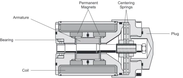
3.1.1 Representative Depiction of a Direct Drive Valve
Figure 1: Representative depiction of the servo-proportional valve
3.1.2 Permanent Magnet Linear Force Motor
The permanent magnet linear force motor is a permanently magnetically ex-cited differential motor. A portion of the magnetic force is already integrated with the permanent magnet. This makes the linear force motor's power re-quirement considerably lower than that of comparable proportional magnets. The linear force motor drives the spool of the servo-proportional valve. In the zero current condition, the centering springs determine the starting position of the spool. The linear force motor enables the spool to be guided in both directions from the starting position, the linear force motor's actuating power being proportional to the coil current. The strong forces from the linear force motor and the centering springs enable precise movement of the spool, even when working against flow and frictional forces.
3.2 Servo-proportional Valve Operational Modes
3.2.1 Flow Control (Q-Control)
During this operating mode the spool position is controlled. The predefined command signal corresponds to a particular spool position. The spool posi-tion is proporposi-tional to the electrical signal.
The command signal (spool position command) is fed to the valve electron-ics. A position transducer (LVDT) measures the spool's actual position and forwards this information to the valve electronics. The electronics compares the actual spool position and command signal and generates a current to drive the linear force motor, which then brings the spool into the correct posi-tion.
The position command can be influenced with parameters in the valve soft-ware (for example: linearization, ramping, dead band, sectionally defined amplification, etc.).
3.2.2 Pressure Control (p-Control)
During this operating mode of the D638 valve the pressure in port A is con-trolled. The predefined command signal corresponds to a particular pressure in port A.
The command signal (pressure command in port A) is transmitted to the valve electronics. A pressure transducer measures the pressure in port A and feeds this to the valve electronics. The electronics compares the actual pressure signal and command signal and generates a current to drive the linear force motor, which then brings the spool into the correct position. The pressure control function can be influenced with parameters in the valve software (for example: linearization, ramping, dead band, sectionally defined amplification, etc.). The pressure regulator is carried out as an extended PID controller. In the valve software, you can set the parameters of the PID con-troller.
3.2.3 Flow Control and Pressure Control (pQ-Control)
(optional for D638)
This is a combination of flow and pressure control for which both command signals (external flow and pressure limit command) must be present.
The following are examples of possible combinations:
• Flow control with pressure limiting control
Permanent magnet linear force motor
Q-Control: Controlling the spool position
p-control: Controlling the pressure in port A
3 Function and Operational Characteristics of the Servo-Proportional Valves CAN Bus and CANopen
3.2.4 Notes on Controller Behavior
The resulting flow depends not only on the position of the spool, but also on the pressure drop ∆p on the individual control edges.
At 100 % flow command signal with a rated pressure drop ∆pN of 35 bar
(500 psi) per control edge, the result is the rated flow QN. By altering the
pressure drop, the flow Q also changes assuming a constant command sig-nal, as shown by the following formula:
N N p p Q Q ∆ ∆ =
Q [l/min] = actual flow QN [l/min] = rated flow
∆p [bar] = actual pressure drop per control edge
∆pN [bar] = rated pressure drop per control edge
The following exert significant influence on the controlled system:
• Rated flow QN
• Actual pressure drop ∆p per control edge
• Load stiffness
• Control volume being regulated by port A (D638 only)
Depending on differences in mechanical construction (such as volume, pipework, branching, reservoirs, etc.), different types of controller optimiza-tions may be required in pressure control. These controller optimizaoptimiza-tions can be carried out with the configuration software via the CAN bus interface.
3.3 CAN Bus and CANopen
The servo-proportional valve is equipped with a CAN bus interface and can be operated within a CAN network.
The CAN bus is a differential 2-wire bus and was initially developed to facili-tate rapid and interference-free networking of components in automobiles. But thanks to its many advantages and high level of reliability, the CAN bus is also suitable for applications within machines and has proven its useful-ness as a widely accepted standard.
CANopen is a standardized communication profile for simple networking of CANopen-compatible devices from many different manufacturers.
The communication profile complies with the DS 301 standard, version 4.0, and is provided by CiA.
The CANopen standard defines various device profiles to enable connection of different types of devices, including for example: drives, controllers, angle transmitters, etc.
The function of the D636 and D638 series valves corresponds to the device profile for proportional servo valves in accordance with the CiA standard DSP 408. This device profile is based on a profile established by a working group within the VDMA entitled "Device Profile Fluid Power Technology".
Formula for calculating the flow Q
CAN bus interface
CANopen communica-tion profile (CiA stand-ard DS 301, version 4.0)
Device profile for pro-portional servo valves (CiA standard DSP 408)
The machine controller or other CAN bus nodes can use the CAN bus to ex-change data with the servo-proportional valve in real time. This data includes command signals and actual values as well as control and status reports. In addition to this real time transmission, configuration and parametric data can be exchanged between the controller and the valve at any time.
The controller or other CAN bus nodes transmit command signals, device control commands, and configuration data via the CAN bus to the servo-pro-portional valve.
The controller or other CAN bus nodes can read actual values, status infor-mation, and the current configuration from the servo-proportional valve. The integrated valve electronics can take over device-specific and drive-specific functions like command signal ramping or dead band compensation. This can relieve the external controller and the CAN communication because external controllers previously had to perform these functions themselves and the interpolated intermediate values had to be transmitted via the CAN bus.
Monitoring, error recognition, and diagnostic functions enable recognition of device malfunctions via the CAN bus.
3.4 Analog
Command
Inputs
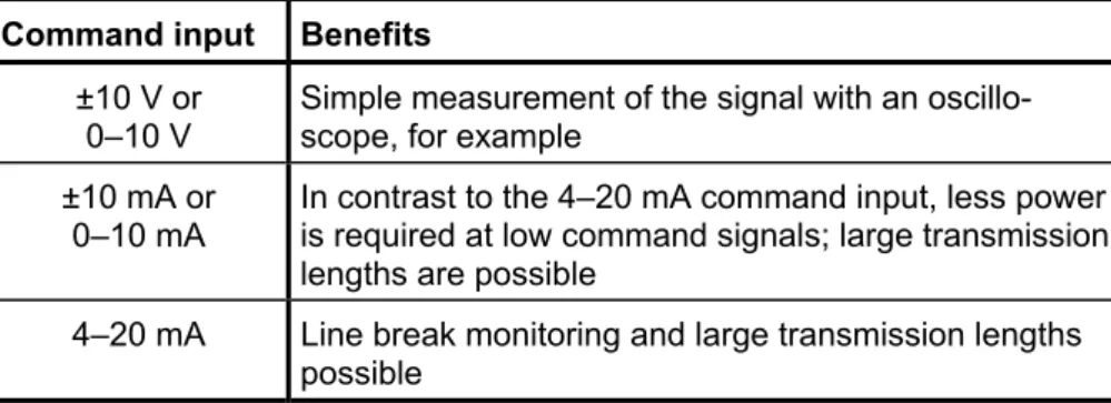
Depending on the valve model, various analog command inputs for flow trol and/or pressure control are available. (Pin assignment of the valve con-nector: see Table 6, page 36)
Command input Benefits
±10 V or
0–10 V Simple measurement of the signal with an oscillo-scope, for example ±10 mA or
0–10 mA
In contrast to the 4–20 mA command input, less power is required at low command signals; large transmission lengths are possible
4–20 mA Line break monitoring and large transmission lengths possible
Table 1: Available analog command inputs
All current inputs are available as floating or single-ended versions. All voltage inputs are floating, but can be connected externally as single-ended inputs. Integrated valve electronics Monitoring, error recognition, and diagnostic functions Analog command inputs
3 Function and Operational Characteristics of the Servo-Proportional Valves Analog Command Inputs
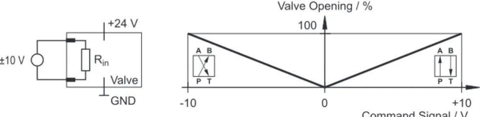
3.4.1 Flow Command Input ±10 V Floating
Figure 3: Flow command input ±10 V floating (circuit and characteristic curve)
The spool stroke is proportional to the input voltage Uin.
Uin = +10 V 100 % valve opening P Ö A and B Ö T
Uin = 0 V Spool in hydraulic null position
Uin = -10 V 100 % valve opening P Ö B and A Ö T
This command input is a floating, differential input. (The potential ence of each input to GND must be between -15 V and +32 V.) If differ-ential voltage is not available, one input pin has to be connected to sig-nal ground according to the required operating direction.
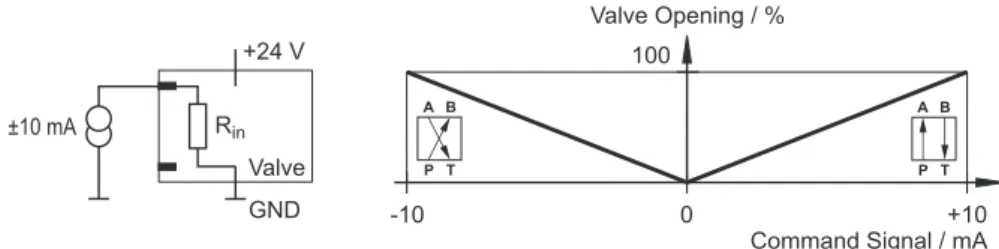
3.4.2 Flow Command Input ±10 mA Floating
Figure 4: Flow command input ±10 mA floating (circuit and characteristic curve)
The spool stroke is proportional to the input current Iin.
Iin = +10 mA 100 % valve opening P Ö A and B Ö T
Iin = 0 mA Spool in hydraulic null position
Iin = -10 mA 100 % valve opening P Ö B and A Ö T
The input current Iin must be between -25 mA and +25 mA!
This command input is a floating input. (The potential difference of each input to GND must be between -15 V and +32 V.) If a floating current source is not available, one input pin has to be connected to signal ground according to the required operating direction.
Flow command input ±10 V floating
Flow command input ±10 mA floating
3.4.3 Flow Command Input ±10 mA Single-Ended
Figure 5: Flow command input ±10 mA single-ended (circuit and characteristic curve)
The spool stroke is proportional to the input current Iin.
Iin = +10 mA 100 % valve opening P Ö A and B Ö T
Iin = 0 mA Spool in hydraulic null position
Iin = -10 mA 100 % valve opening P Ö B and A Ö T
The point of reference for this command input is GND.
The input current Iin must be between -25 mA and +25 mA!
Depending on the required operating direction, one of the two input pins must not be connected.
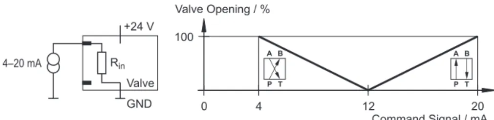
3.4.4 Flow Command Input 4–20 mA Floating
Figure 6: Flow command input 4–20 mA floating (circuit and characteristic curve)
The spool stroke is proportional to the input current Iin.
Iin = 20 mA 100 % valve opening P Ö A and B Ö T
Iin = 12 mA Spool in hydraulic null position
Iin = 4 mA 100 % valve opening P Ö B and A Ö T
The input current Iin must be between -25 mA and +25 mA!
This command input is a floating input. (The potential difference of each input to GND must be between -15 V and +32 V.) If a floating current source is not available, one input pin has to be connected to signal ground according to the required operating direction.
Command signals Iin < 3 mA (due to line break, for example) indicate an
error during flow control. The valve is switched off for safety reasons and goes into fail-safe position.
Flow command input ±10 mA single-ended
Flow command input 4–20 mA floating
3 Function and Operational Characteristics of the Servo-Proportional Valves Analog Command Inputs
3.4.5 Flow Command Input 4–20 mA Single-Ended
Figure 7: Flow command input 4–20 mA single-ended (circuit and characteristic curve)
The spool stroke is proportional to the input current Iin.
Iin = 20 mA 100 % valve opening P Ö A and B Ö T
Iin = 12 mA Spool in hydraulic null position
Iin = 4 mA 100 % valve opening P Ö B and A Ö T
The point of reference for this command input is GND.
The input current Iin must be between -25 mA and +25 mA!
Depending on the required operating direction, one of the two input pins must not be connected.
Command signals Iin < 3 mA (due to line break, for example) indicate an
error during flow control. The valve is switched off for safety reasons and goes into fail-safe position.
3.4.6 Pressure Command Input 0–10 V Floating (D638)
Figure 8: Pressure command input 0–10 V floating (circuit and characteristic curve)
The pressure in control port A is proportional to the input voltage Uin.
Uin = 10 V 100 % pressure in control port A
Uin = 0 V 0 % pressure in control port A
This command input is a floating, differential input. (The potential ence of each input to GND must be between -15 V and +32 V.) If differ-ential voltage is not available, one input pin has to be connected to sig-nal ground.
Flow command input 4–20 mA single-ended
Pressure command input 0–10 V floating (D638)
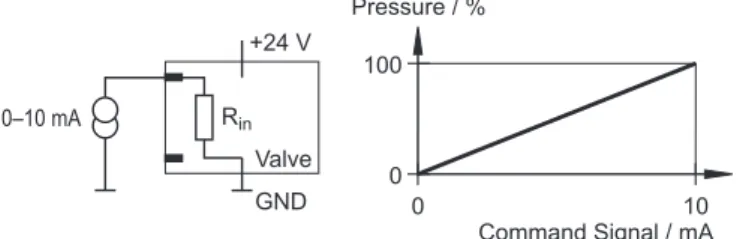
3.4.7 Pressure Command Input 0–10 mA Floating (D638)
Figure 9: Pressure command input 0–10 mA floating (circuit and characteristic curve)
The pressure in control port A is proportional to the input current Iin.
Iin = 10 mA 100 % pressure in control port A
Iin = 0 mA 0 % pressure in control port A
The input current Iin must be between -25 mA and +25 mA!
This command input is a floating input. (The potential difference of each input to GND must be between -15 V and +32 V.) If a floating current source is not available, create a connection to 0 V of the command sig-nal source.
3.4.8 Pressure Command Input 0–10 mA Single-Ended
(D638)
Figure 10: Pressure command input 0–10 mA single-ended (circuit and characteristic curve)
The pressure in control port A is proportional to the input current Iin.
Iin = 10 mA 100 % pressure in control port A
Iin = 0 mA 0 % pressure in control port A
The point of reference for this command input is GND.
The input current Iin must be between -25 mA and +25 mA!
Only one of the two input pins must be connected.
Pressure command input 0–10 mA floating (D638) Pressure command input 0–10 mA single-ended (D638)
3 Function and Operational Characteristics of the Servo-Proportional Valves Analog Command Inputs
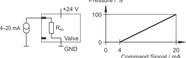
3.4.9 Pressure Command Input 4–20 mA Floating (D638)
Figure 11: Pressure command input 4–20 mA floating (circuit and characteristic curve)
The pressure in control port A is proportional to the input current Iin.
Iin = 20 mA 100 % pressure in control port A
Iin = 4 mA 0 % pressure in control port A
The input current Iin must be between -25 mA and +25 mA!
This command input is a floating input. (The potential difference of each input to GND must be between -15 V and +32 V.) If a floating current source is not available, create a connection to 0 V of the command sig-nal source.
Command signals Iin < 3 mA (due to line break, for example) indicate an
error during pressure control. The valve is switched off for safety rea-sons and goes into fail-safe position.
3.4.10 Pressure Command Input 4–20 mA Single-Ended
(D638)
Figure 12: Pressure command input 4–20 mA single-ended (circuit and characteristic curve)
The pressure in control port A is proportional to the input current Iin.
Iin = 20 mA 100 % pressure in control port A
Iin = 4 mA 0 % pressure in control port A
The point of reference for this command input is GND.
The input current Iin must be between -25 mA and +25 mA!
Only one of the two input pins must be connected.
Pressure command input 4–20 mA floating (D638) Pressure command input 4–20 mA single-ended (D638)
3.5 Analog Actual Value Outputs
Depending on the valve model, various analog actual value outputs for flow control and/or pressure control (optional) are available. (Pin assignment of the valve connector: see Table 6, page 36)
3.5.1 Actual Flow Value Output 4–20 mA
The output current Iout is proportional to the spool stroke.Iout = 20 mA 100 % valve opening P Ö A and B Ö T
Iout = 12 mA Spool in hydraulic null position
Iout = 4 mA 100 % valve opening P Ö B and A Ö T
GND is the point of reference for the actual value output 4–20 mA.
Line breaks can be recognized externally with the 4–20 mA actual value output.
The 4–20 mA output is short-circuit protected.
3.5.2 Actual Pressure Output 4–20 mA (D638)
The output current Iout is proportional to the pressure in control port A.
Iout = 20 mA 100 % pressure in control port A
Iout = 4 mA 0 % pressure in control port A
GND is the point of reference for the actual value output 4–20 mA.
Line breaks can be recognized externally with the 4–20 mA actual value output.
The 4–20 mA output is short-circuit protected.
3.5.3 Evaluation of the 4–20 mA Actual Value Output
The 4–20 mA outputs can be evaluated in accordance with the following cir-cuit.
Figure 13:
Circuit for measuring the actual value Iout
for valves with 6+PE-pin valve connectors
Analog actual value outputs
Evaluation of the actual value outputs
3 Function and Operational Characteristics of the Servo-Proportional Valves Digital Inputs/Outputs
3.6 Digital
Inputs/Outputs
Depending on the valve model, different digital inputs and outputs are avail-able.
3.6.1 Enable Input (optional)
Signals to the enable input from 8.5 VDC to 24 VDC (based on GND) enable the operation of the valve. Signals of less than 6.5 VDC force the valve into fail-safe mode. (Pin assignment of the 6+PE-pin valve connector, see page 36)
If the enable input is not activated, the valve will be in fail-safe mode.
The D636 and D638 servo-proportional valves are also available without the enable input.
3.6.2 Digital Outputs
Depending on the model, up to two optional digital outputs are available.
3.7 Status
Display
The valve's operating mode and the network status are displayed on multi-color light emitting diodes (status display LEDs) on the electronics housing.
After the valve's power supply is switched on, the valve electronics perform a self-test, indicated by red and green blinking LEDs.
3.7.1 Module Status LED «MS»
The module status LED displays an available power supply and possible opera-tional and error states.
Module status LED «MS» Condition
off no supply power
green normal operation
blinking green valve standby mode blinking red correctable error
red unrecoverable error
blinking red-green self-test
Table 2: Conditions of the module status LED «MS»
Digital inputs/outputs
Digital inputs: enable input
Digital outputs
Status display LEDs
Figure 14: Status display LEDs
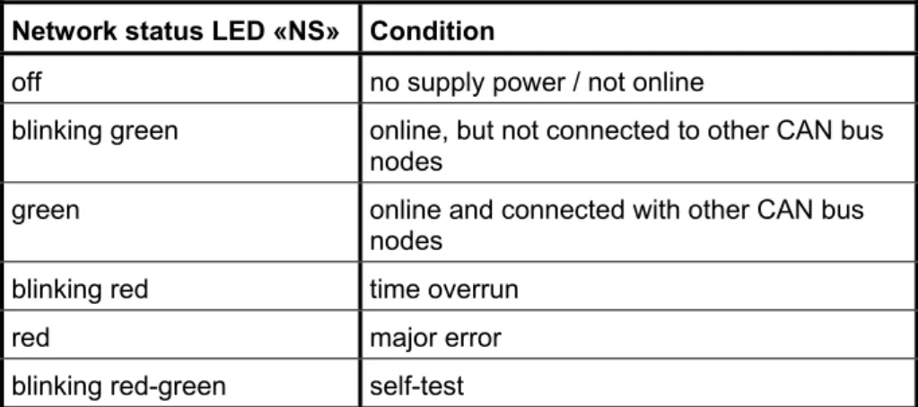
3.7.2 Network Status LED «NS»
The network status LED displays the status of the CAN network.
Network status LED «NS» Condition
off no supply power / not online
blinking green online, but not connected to other CAN bus nodes
green online and connected with other CAN bus nodes
blinking red time overrun
red major error
blinking red-green self-test
Table 3: Conditions of the network status LED «NS»
3 Function and Operational Characteristics of the Servo-Proportional Valves Status Display
4
Technical Data and Scope of Delivery
4.1 General Technical Data
Maximum operating pressure
Ports P and B 350 bar (5,000 psi) Port A
for D636 350 bar (5,000 psi)
for D638 dependent on pressure transducer, max. 350 bar (5,000 psi)
Port T without Y 50 bar (724 psi) (see chapter 4.2.2, page 24) Port T with Y 350 bar (5,000 psi)
Port Y depressurized to the tank
Allowable ambient conditions
Ambient temperature -20 °C to +60 °C
Vibration resistance 30 g, 3 axes, frequency: 5–2,000 Hz Shock resistance 60 g, 6 directions, half-sine 11 ms
Gasket material HNBR, FPM, others upon request
Hydraulic fluid
Allowable fluids Mineral oil-based hydraulic fluid
in accordance with DIN 51524 parts 1–3, other fluids upon request
Allowable temperature -20 °C to +80 °C Viscosity ν
recommended 15-100 mm²/s
allowable 5-400 mm²/s
Cleanliness level, recommended
for functional safety ISO 4406 < 15 / 12 for life cycle
(wear and tear)
ISO 4406 < 14 / 11
The cleanliness of the hydraulic fluid greatly influences the functional safety (safe positioning of the spool, high resolution) and the wear-ing protection (control edges, pressure gain, leakage losses) of the valve.
System filter
High pressure filter (without bypass, but with dirt indication) in the main flow path directly in front of the valve, as close as possible
Filter fineness, recommended
for functional safety β10≥ 75 (10 µm (0.0004 in) absolute)
for life cycle (wear and tear)
β6≥ 75 (6 µm (0.00024 in) absolute)
Shipping plate
4 Technical Data and Scope of Delivery Hydraulic Data
Mounting option
any position, fixed or movable.
When mounting the valve, follow the safety instructions from chapter 6, starting on page 31.
Mounting surface
Flatness: < 0.01 mm (0.0004 in) over 100 mm (3.9 in) Average surface finish, Ra: < 0.8 µm (32 µin)
Mass 2.5 kg (5.5 lb)
4.2 Hydraulic
Data
Valve construction type Single stage, sliding spool with bushing
Mounting pattern in accordance with ISO 4401-03-03-0-94 (with or without leakage port Y, see page 24)
∅ of the ports 7.9 mm (0.3 in)
Valve configuration 2-way, 3-way, 4-way, and 2x2-way operation
Actuation directly with permanent magnet linear force motor
Pilot oil supply none
Rated flow QN 5 (1.3) / 10 (2.6) / 20 (5.3) / 40 (10.6) l/min (gpm)
(depending on the model) (at ∆pN = 35 bar
(500 psi) per control edge, tolerance ±10 %)
Max. leakage flow QL1) 0.15 (0.040) / 0.3 (0.079) / 0.6 (0.16) /
1.2 (0.32) l/min (gpm) (depending on the model)
Max. flow 75 l/min (19.8 gpm)
Spool lap Zero lap, < 3 % or 10 % positive lap (depending on the model)
Step response time for
0 to 100 % stroke 12 ms (typical) Threshold 1) < 0.1 % (in Q-control)
Hysteresis 1) < 0.2 % (in Q-control)
Null shift < 1.5 % (at ∆T = 55 K)
Linearity of pressure control (only with D638)
< 0.5 % F.S.
4.2.1 Servo-Proportional Valve Configurations
The following valve configurations are possible with the D636/D638 (op-tional) valves:
• 4-way operation
• 3-way operation
• 2-way operation
• 2x2-way operation
4-way and 3-way operation
In 4-way operation, the servo-proportional valves can be used to control the flow in ports A and B (use as throttle valves).
To obtain the 3-way operation, close either port A or port B.
If the pressure in the tank port T exceeds 50 bar (724 psi), the leakage port Y must be used (see chapter 4.2.2, page 24).
The valves are available with zero lap, less than 3 % or 10 % positive lap.
Figure 15: 4-way/3-way operation with fail-safe function (hydraulic symbols)
2-way and 2x2-way operation
In 2-way and 2x2-way operation, the servo-proportional valves can be used to control the flow in one direction (use as throttle valves).
In 2x2-way operation, the valve can be used in 2-way applications for higher flows. To do this, the port P must be connected externally to B and A exter-nally with T.
For 2x2-way operation, the leakage port Y must always be connected (see chapter 4.2.2, page 24).
Figure 16: 2-way/2x2-way operation (hydraulic symbols)
Valve configurations
4-way and 3-way operation
2-way and 2x2-way operation
4 Technical Data and Scope of Delivery Electrical Data
4.2.2 Leakage Port Y
D636 and D638 servo-proportional valves can be delivered with or without the leakage port Y active.
Purchase orders for the valve must indicate whether port Y will be used. The leakage port Y must be used in the following cases:
• if the pressure in the tank port T becomes greater than 50 bar (724 psi)
• with 2x2-way operation
4.3 Electrical
Data
Supply power nominal 24 VDC, 18 to 32 VDC Duty cycle 100 % Valve connector6+PE pin connector with pin contacts in accordance with DIN EN 175201-804
Protection type in accordance with DIN EN 60529
IP65 without connectors
IP67 connectors plugged and locked
Power consumption
Pmin (motor in neutral position) 9.6 W (0.4 A at 24 VDC)
Pmax (at max. flow) 28.8 W (1.2 A at 24 VDC)
EMC protection requirements
in accordance with DIN EN 55011, DIN EN 50081-2 and DIN EN 61000-6-2 Inputs/outputs Command input 0–10 V Rin = 300 kΩ Command input ±10 V Rin = 300 kΩ Command input 0–10 mA Rin = 200 Ω Command input ±10 mA Rin = 200 Ω Command input 4–20 mA Rin = 200 Ω
Actual value output 4–20 mA RL max. = 500 Ω with respect to GND
Enable input (function:
see chapter 3.6.1, page 18) Signals to the enable input from 8.5 VDC to 24 VDC (based on GND) enable the operation of the valve. Signals of less than 6.5 VDC force the valve into fail-safe mode.
Leakage port Y
CAN bus interface
CAN connector 5-pin connector with pin contacts (M12 x 1)
Physical DIN ISO 11898 CAN-HIGH SPEED
Communication profile CANopen DS 301, version 4.0
Device profile CANopen DSP 408
Maximum voltage capacity 40 VDC
External fusing for each valve
1.6 A slow-blow
4.4 Characteristic
Curves
4.4.1 Step Response, Frequency Response, and Flow Diagram
Figure 17: Step response
4 Technical Data and Scope of Delivery Characteristic Curves
4.4.2 Flow Characteristic Curve
4.4.3 Pressure Characteristic Curves
Figure 20: Flow characteristic curve
Figure 21: Flow characteristic curve
(zero cut)
Figure 22: Design for measuring the
flow characteristic curve
Figure 23:
Pressure characteristic curve of flow control valves
Figure 24: Design for measuring the pressure characteristic curve
of flow control valves
4.5 Dimensions
(Installation Drawing)
Figure 27: Installation drawing (dimensions in mm, values in parenthesis in inches)
4.6 Mounting Pattern and Mounting Surface
Figure 28:
Mounting Pattern, ISO 4401-03-03-0-94, without port X (dimensions in mm, values in parenthesis in inches)
P A B T X1 Y F 1 F2 F3 F4 G2 ∅ 7.5 (0.30) ∅ 7.5 (0.30) ∅ 7.5 (0.30) ∅ 7.5 (0.30) - ∅ 3.3 (0.13) M5 M5 M5 M5 ∅ 4.0 (0.16) x (0.85) 21.5 (0.50) 12.7 (1.19) 30.2 (0.85) 21.5 - (1.59) 40.5 0 (1.59) 40.5 (1.59) 40.5 0 (1.30) 33 y (1.02) 25.9 (0.61) 15.5 (0.61) 15.5 (0.20) 5.1 - (0.35) 9.0 0 (-0.03) -0.75 (1.25) 31.75 (1.22) 31 31.75(1.25)
4 Technical Data and Scope of Delivery Scope of Delivery
4.7 Scope
of
Delivery
The following items are included in delivery of the valve:
• Servo-proportional valve with attached oilproof shipping plate on the hydraulic ports
• 4 O-rings ID 9.25 (0.36) x ∅ 1.8 (0.07) for the P, T, A, B ports (dimensions in mm, values in parenthesis in inches)
• 1 O-ring ID 7.65 (0.30) x ∅ 1.8 (0.07) for the Y port (dimensions in mm, values in parenthesis in inches)
5
Transport and Storage
The allowable environmental conditions (see chapter 4, page 21) must be maintained at all times.
Do not transport or store the servo-proportional valves without first properly installing the shipping plate.
5.1 Packaging/Transport
Please read the following carefully:
• Do not damage valves during packaging or transportation.
• Transport valves only in the properly closed original packaging.
• Store the valve's original packaging for later use.
• Immediately inform the freight company and Moog in writing about any damages incurred during transportation.
• Remove the shipping plate only directly before mounting the valve.
• Store the shipping plate and the accompanying attachment screws.
• Always install the shipping plate before transporting the valves.
5.2 Storage
Please read the following carefully:
• Store valves only in the properly closed original packaging.
• Protect valves from dust and moisture.
• Always install the shipping plate before transporting the valves in order to protect the valve from the entry of dirt or moisture.
Safety instructions for transport and storage
Packaging/transport
5 Transport and Storage Storage
6
Mounting/Removing and Connection to
the Hydraulic System
The servo-proportional valves must only be mounted and removed, and electrical and hydraulic connections made by suitably trained technical personnel with the necessary authorization. They must perform such tasks in accordance with the applicable regulations and the valve must be in an idle and depressurized state and the
machine switched off.
While this work is in progress, the machine must be secured against restarting, for example by:
• Locking the main command device and removing the key and/or
• attaching a warning sign to the main switch
Hydraulic oil can cause serious injuries, burns, and fires if it squirts out under high pressure.
Before mounting or removing servo-proportional valves, all pressure lines and reservoirs in the hydraulic circuit must therefore be de-pressurized.
Servo-proportional valves and hydraulic connection lines may be-come very hot while in operation.
When mounting, removing, or servicing servo-proportional valves, always wear suitable protective equipment such as work gloves. When handling hydraulic fluids, always follow the safety guidelines applicable to the product.
Technical data and especially the information on the servo-propor-tional valve's nameplate must be read carefully and complied with. Remove the shipping plate from the hydraulic ports only shortly be-fore placing the servo-proportional valve on the mounting surface. Always check the mounting surface for dirt (and clean if necessary) immediately before mounting the valve.
To avoid overheating the servo-proportional valve, mount it in a way that ensures good ventilation.
Do not mount valves directly onto mechanical parts that are subject to strong vibrations or sudden movement.
When mounted on units subject to sudden movement, the spool di-rection should not be the same as the unit's didi-rection of movement. If a servo-proportional valve contains a venting screw (D638), al-ways mount the valve in such a way that it can be vented.
In order to allow air that may be contained in the valve to escape af-ter the venting screw is opened, make sure the venting screw points upward.
Safety instructions for mounting/removing and connection to the hydraulic system
6 Mounting/Removing and Connection to the Hydraulic System Mounting the Servo-Proportional Valve
6.1 Mounting the Servo-Proportional Valve
Never use the shipping plate's attachment screws to attach the servo-proportional valve.
The mounting surface must be free of residue and dirt during mount-ing of the servo-proportional valve. Use a clean, soft, and lint free cloth to clean the mounting surface. Do not use cleaning wool or waste cotton.
Do not use cleaning methods that could attack the mounting surface mechanically or chemically.
If a servo-proportional valve contains a venting screw (D638), al-ways mount the valve in such a way that it can be vented.
In order to allow air that may be contained in the valve to escape af-ter the venting screw is opened, make sure the venting screw points upward.
A 4 mm Allen wrench is needed to mount the servo-proportional valve.
The servo-proportional valve may be mounted in any position, fixed or movable. For characteristics of the mounting surface, see chap-ter 4.1, page 22.
Procedure for mounting the servo-proportional valve:
1. Clean the mounting surface.
2. Remove the shipping plate from the valve's hydraulic ports and re-tain it for later use, for example maintenance.
3. Check that O-rings are available for the ports and that they are in the correct position.
4. Place the valve on the mounting surface and adjust it so it aligns with the mounting holes.
5. Fasten the valve by alternately tightening each of the installation screws (Allen screws) without distortion (see table below for proper tightening torque).
Tightening torque ±10 % (in accordance with
DIN EN ISO 4762) Installation screws
(in accordance with DIN EN ISO 4762) Quan
tity
Quality class 10.9 Quality class 12.9 M 5 x 55 mm (2.2 in) 4 6.8 Nm (60.2 lb-in) 10 Nm (89 lb-in)
Table 5: Installation material and tightening torque values
Mounting the servo-proportional valve
6.2 Removing the Servo-Proportional Valve
The servo-proportional valves must only be mounted and removed, and electrical and hydraulic connections made by suitably trained technical personnel with the necessary authorization. They must perform such tasks in accordance with the applicable regulations and the valve must be in an idle and depressurized state and the
machine switched off.
While this work is in progress, the machine must be secured against restarting, for example by:
• Locking the main command device and removing the key and/or
• attaching a warning sign to the main switch
Hydraulic oil can cause serious injuries, burns, and fires if it squirts out under high pressure.
Before mounting or removing servo-proportional valves, all pressure lines and reservoirs in the hydraulic circuit must therefore be de-pressurized.
Attach the shipping plate to the hydraulic ports immediately after removing the valve.
A 4 mm Allen wrench is needed to remove the valve.
The valve is removed in the reverse order to the mounting.
Procedure for removing the servo-proportional valve:
1. Loosen the valve's installation screws. 2. Remove the valve from the mounting surface.
3. Check that O-rings are available for the ports and that they are in the correct position.
4. Attach the shipping plate to the hydraulic ports. 5. Store the servo valve in the original packaging.
6. Cover the ports of the hydraulic system to prevent contamination.
Removing the servo-proportional valve
6 Mounting/Removing and Connection to the Hydraulic System Removing the Servo-Proportional Valve
7 Electrical
Connection
The servo-proportional valves must only be mounted and removed, and electrical and hydraulic connections made by suitably trained technical personnel with the necessary authorization. They must perform such tasks in accordance with the applicable regulations and the valve must be in an idle and depressurized state and the
machine switched off.
While this work is in progress, the machine must be secured against restarting, for example by:
• Locking the main command device and removing the key and/or
• attaching a warning sign to the main switch
Servo-proportional valves and hydraulic connection lines may be-come very hot while in operation.
When mounting, removing, or servicing servo-proportional valves, always wear suitable protective equipment such as work gloves. When handling hydraulic fluids, always follow the safety guidelines applicable to the product.
Technical data and especially the information on the servo-propor-tional valve's nameplate must be read carefully and complied with. Do not place the servo-proportional valve's connection cables in the immediate vicinity of high voltage lines or together with cables that switch inductive or capacitive loads.
An EMC-compliant power unit must be used for the supply voltage. The electrical connection must be completed in an EMC-compliant manner.
Procedure for establishing the servo-proportional valve's electrical connection:
1. Wire the servo-proportional valve in accordance with the pin as-signment described in chapter 7.1 (page 36).
2. Construct the equipotential system, the protective ground, and shielding in accordance with the enclosed TN 353 technical note. 3. Construct CAN bus wiring as described in chapter 7.2 (page 37).
Safety instructions for electrical connection
Electrical connection of the servo-propor-tional valve
7 Electrical Connection Pin Assignment
7.1 Pin
Assignment
7.1.1 Valve Connector
Table 6: Pin assignment of the 6+PE-pin valve connector
Figure 29: Pin assignment of the 6+PE-pin valve connector (looking towards the connector on the valve) Pin Signal type Signal Voltage floating ±10 V, 0–10 V Current floating ±10 mA, 0–10 mA, 4–20 mA Current single-ended ±10 mA, 0–10 mA, 4–20 mA A Supply voltage 24 VDC (18 to 32 VDC)
B Power ground / signal ground 0 V (GND)
C Enable input 8.5–24 VDC based on pin B: operation of the valve enabled < 6.5 VDC based on pin B: valve fail-safe condition (see also chapter 3.6.1, page 18)
The potential difference (measured against pin B) must be between -15 V and +32 V.
Uin = UDE Rin = 300 kΩ Iin = ID = -IE Rin = 200 Ω Iin = ID Rin = 200 Ω
differential Do not connect Pin E!
The input current Iin must be between -25 mA and
+25 mA!
D E
Command input
Command signals Iin < 3 mA (due to line break, for
ex-ample) indicate an error during flow control for inputs of 4-20 mA. The valve is switched off for safety rea-sons and goes into fail-safe position.
F Actual value output Ithe regulated pressure (on D638); the output is short-circuit protected; for inter-out: 4–20 mA based on GND (Iout is proportional to the position of the spool or to pretation of the actual value output, see chapter 3.5.3, page 17); RL: 0-500 Ω
7.1.2 CAN Connector
Pin Signal
1 CAN_SHLD shield
2 CAN_V+ is not attached in the valve 3 CAN_GND
4 CAN_H Transceiver H 5 CAN_L Transceiver L
Table 7: Pin assignment of the CAN connector
Figure 30: Pin assignment of the CAN connector (looking towards the CAN connector on the valve)
Alignment of the CAN connector may vary. Please align the pins in accordance with the key.
We recommend the use of molded cord sets with a straight mating connector (see Table 11, page 40).
7 Electrical Connection Wiring CAN Networks
7.2 Wiring CAN Networks
The servo-proportional valve is equipped with a galvanically isolated CAN bus interface. The CAN bus interface is supplied internally; it is therefore not absolutely necessary to connect CAN_V+ 24 VDC (pin 2 of the CAN connec-tor).
Note the following points when wiring CAN networks:
• All cables, plug connectors, and terminal resistors used in CAN net-works must comply with DIN ISO 11898.
• In general, it is important to comply with all information in the enclosed TN 353 technical note.
• Use shielded four-lead cables (twisted pair) and surge impedance of 120 Ω (CAN_H, CAN_L, CAN_GND and CAN_SHLD (cable shield) grounded, optionally CAN_V+ 24 VDC).
• A CAN bus cable must not branch but short stub cables with T-connectors are allowed.
• Stub cables must be as short as possible (for the maximum stub cable length, see Table 10, page 40).
• The cable between CAN_L and CAN_H on both CAN bus cable ends must be ended by a terminal connector with terminal resistance of 120 Ω ± 10 %.
• Connect reference potential CAN_GND and CAN_SHLD to the pro-tective ground (PE) at only one point (on a terminal connector, for example).
• The transmission rate must be adapted to the CAN bus cable length (see Table 8, page 39).
• Do not lay CAN bus cables in the immediate vicinity of EMI sources. If EMI sources cannot be avoided, use double shielded cables.
For CAN bus nodes without a galvanically isolated CAN bus inter-face, CAN_GND is generally connected to the 0V supply voltage in-side the device. In these cases, the supply voltage connection cable must be grounded at the same place as the CAN_GND connection cable.
To avoid noise in extensive CAN networks, avoid CAN bus nodes that do not have galvanically isolated CAN bus interfaces.
If it is not possible to refrain from CAN bus nodes that do not have galvanically isolated CAN bus interfaces, arrange these nodes in the immediate vicinity of the central ground point. The cable length to this central ground point should be kept as short as possible!
7.2.1 Cable Lengths and Cable Cross Sections in
CAN Networks
Transmission rate Maximum cable length
1,000 kbit/s 25 m (984 in) 800 kbit/s 50 m (1,969 in) 500 kbit/s 100 m (3,937 in) 250 kbit/s 250 m (9,843 in) 125 kbit/s 500 m (19,685 in) 100 kbit/s 650 m (25,591 in) 50 kbit/s 1,000 m (39,370 in) 20 kbit/s 2,500 m (98,425 in) 10 kbit/s 5,000 m (196,850 in)
Table 8: Recommendation for maximum cable lengths in CAN networks, depending on the transmission rate
Maximum cable length for n CAN bus nodes
Cable cross section n = 32 n = 64 n = 100
0.25 mm² (22 AWG) 200 m
(7,874 in) (6,693 in) 170 m (5,906 in) 150 m 0.5 mm² (20 AWG) 360 m
(14,173 in) (12,305 in) 310 m (10,623 in) 270 m 0.75 mm² (18 AWG) 550 m (21,654 in) 470 m (18,504 in) 410 m (16,142 in)
Table 9: Recommendation for maximum cable lengths in CAN networks, depending on the cable cross section and the number of CAN bus nodes
Recommendation for maximum cable lengths in CAN networks
7 Electrical Connection Wiring CAN Networks
Maximum stub cable length
Transmission rate Maximum Cumulative
1,000 kbit/s 2 m (78.7 in) 20 m (787 in) 500 kbit/s 6 m (236 in) 39 m (1,535 in) 250 kbit/s 6 m (236 in) 78 m (3,071 in) 125 kbit/s 6 m (236 in) 156 m (6,142 in)
Table 10: Maximum allowable stub cable lengths in CAN networks
7.2.2 Suitable Cable Types
Manufacturer Cable type
Hans Turck GmbH & Co. KG Witzlebenstraße 7
45472 Mülheim an der Ruhr Germany
Tel.: +49-208-4952-0, Fax: +49-208-4952-264
E-mail: [email protected] http://www.turck.com
577 Flexlife thin cable, 5710 Flexlife mid cable, 575 Flexlife thick cable
Table 11: Suitable cable types for CAN networks
Maximum allowable stub cable length in CAN networks
Suitable cable types for CAN networks
8 Starting-Up
the
Servo-Proportional
Valve
The servo-proportional valves must only be mounted and removed, and electrical and hydraulic connections made by suitably trained technical personnel with the necessary authorization. They must perform such tasks in accordance with the applicable regulations and the valve must be in an idle and depressurized state and the
machine switched off.
While this work is in progress, the machine must be secured against restarting, for example by:
• Locking the main command device and removing the key and/or
• attaching a warning sign to the main switch
Operating machines with leaking servo-proportional valves or a leak-ing hydraulic system is dangerous and not allowed.
When starting-up a servo-proportional valve on a field bus for the first time, we recommend operating the valve in a depressurized state.
Hydraulic oil can cause serious injuries, burns, and fires if it squirts out under high pressure.
Before mounting or removing servo-proportional valves, all pressure lines and reservoirs in the hydraulic circuit must therefore be de-pressurized.
Servo-proportional valves and hydraulic connection lines may be-come very hot while in operation.
When mounting, removing, or servicing servo-proportional valves, always wear suitable protective equipment such as work gloves. When handling hydraulic fluids, always follow the safety guidelines applicable to the product.
Technical data and especially the information on the servo-propor-tional valve's nameplate must be read carefully and complied with. Remove the shipping plate from the hydraulic ports only shortly be-fore placing the servo-proportional valve on the mounting surface. Attach the shipping plate to the hydraulic ports immediately after removing the valve.
Fresh oil is contaminated. When filling the hydraulic system, always use a filling filter with a fineness of at least β10≥ 75 (10 µm
abso-lute).
Safety instructions for starting-up the servo-proportional valve
8 Starting-Up the Servo-Proportional Valve Filling and Flushing the Hydraulic System
The following steps are necessary when starting-up the servo-propor-tional valve:
1. Prepare the hydraulic system in accordance with chapter 8.1 (page 42).
2. Mount the valve in accordance with chapter 6.1 (page 32).
3. Wire the valve's electrical connection in accordance with chapter 7 (starting on page 35).
4. Connect the valve to the field bus in accordance with chapter 8.3 (starting on page 43).
A Windows-based configuration program is available that simplifies start-up on the CAN bus.
The configuration software is a graphical user interface that simplifies parameterization and diagnosis of the servo-propor-tional valve and enables the execution of a valve test.
See the configuration software's handbook or the configura-tion software's online help for descripconfigura-tions of the configuraconfigura-tion software.
5. Start-up the hydraulic system in accordance with chapter 8.2 (start-ing on page 43).
8.1 Filling and Flushing the Hydraulic System
Procedure for filling and flushing the hydraulic system: 1. Depressurize the hydraulic system.
2. Fill the hydraulic system in accordance with the instructions provided by the system manufacturer.
3. Before starting the flushing process, insert into the pressure filter suitable flushing elements in place of the high pressure filter ele-ments.
4. Remove the servo-proportional valve (see chapter 6.2, page 33). 5. Instead of the servo-proportional valve, you must install a flushing
plate or, if allowed by the system, a switching valve.
This switching valve must not introduce any potentially dan-gerous conditions into the system.
Use the flushing plate to flush the lines P and T.
The switching valve can also be used to flush the actuator with lines A and B.
6. Carefully flush the hydraulic system in accordance with the manufac-turer's instructions.
While doing this, please observe the following:
• The hydraulic oil's operating temperature should be reached during the flushing process.
• Observe the minimum flushing time: t = (V/Q) x 5 [h] (V = tank contents in l, Q = pump flow rate in (l/min))
• End the flushing process when the system cleanliness level of 15/12 as specified by ISO 4406 or class 6 as speci-fied by NAS 1638 or better has been achieved.
7. Depressurize the hydraulic system.
Starting-up the servo-proportional valve
Filling and flushing the hydraulic system