136
R E C O M M E N D A T I O N S FOR
T H E
D E S I G N A N D C O N S T R U C T I O N
OF B A S E I S O L A T E D S T R U C T U R E S
1 2 3 4
R . W . G . B l a k e i e y , A. W . C h a r l e s o n , H.C. H i t c h c o c k , L . M . M e g g e t , M. J . N . P r i e s t l e y b f R.D. S h a r p e6 R.I. S k i n n e r7
SYNOPSIS
The philosophy of base isolation of structures, generally using flexible mountings and mechanical energy dissipating devices, is reviewed. Applications of the approach to buildings, bridges, nuclear power plants, equipment and structures rocking on their foundations are described. Where possible, recommended code provisions and design rules are given. The characteristics of the mechanical energy dissipating devices developed to date are discussed and material specification provisions presented. The requirements for construction of base isolated structures and for maintenance of the devices are given. Finally, recommendations are made on matters for future research.
The authors comprise a working group set up by the Management Committee of the New Zealand National Society for Earthquake Engineering to prepare recommendations for the design and construction of base isolated
structures 3 suitable for the guidance of
designers and approving authorities.
1. PHILOSOPHY
1.1 Principles of Base Isolation 1.1.1 Base Isolation - A Description
The forces that begin to act on a structure during an earthquake arise through the reluctance of that structure to comply rigidly with the motion of the ground surround-ing its foundations, that is the structure mass above ground level 1 w a n t s1 to remain
stationary while the ground beneath moves. The magnitude of the forces induced is dependent on both the characteristics of the ground movement and the stiffness of the elements of the structure fixing it to the ground. If the elements connecting the ground and the majority of the inertial mass were broken during the earthquake attack, then the mass would no longer be forced to respond and the structure above the break would not be seismically loaded. This, then, is the principle of seismic protection by base isolation.
Because of the need to provide continuous support for the vertical loading of the
superstructure, the principles of base isolation are more easily applied to 1. Senior Design Engineer, Ministry of
Works and Development.
2. Senior Engineer, Ministry of Works and Development.
3. Retired, formerly Research and Develop-ment Engineer, N.Z.E.D.
4. Senior Lecturer, Victoria University School of Architecture.
5. Reader, University of Canterbury, Department of Civil Engineering. 6. Formerly Beca, Carter, Hollings and
Ferner, Ltd., Consulting Engineers. 7. Head of Engineering Seismology Section,
D.S.I. R.
horizontally induced loadings. The ideal described above of a system with no horizontal restraint has in practice to accommodate frequent horizontal service loads such as wind. The practical system of base isolation usually comprises the following two elements:
(a) The structure is supported on horizontally flexible mountings to isolate it from the greatest disturbing motions at the likely
predominant earthquake ground motion frequencies, and
(b) Sufficient extra damping is introduced into the system to reduce resonance effects and keep deflections within acceptable limits. 1.1.2 Importance of Earthquake Characteristics
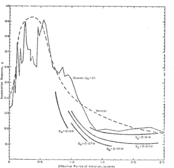
The effect of introduction of flexible mountings is illustrated in Fig. 1. Strong motion accelerograms recorded in areas of hard rock or stiff alluvial soil have typically exhibited a predominant frequency of about 3 Hz, as illustrated by the spectrum for the El Centro 1940 N-S record. For such an earthquake introduction of flexible mountings to an otherwise stiff structure in this period range will dramatically reduce the acceleration response. However, it must be recognised that soft soils and other factors may alter the frequency response of an earth-quake so that more of the energy is transmitted at low frequencies. An example of an earth-quake record with predominant low frequencies is the Bucharest, 1977, record shown in Fig. 1. For such an earthquake, introduction of flexible mountings will tend to increase rather than decrease response, as demonstrated by Priestley and S t o c k w e l l .
There are few strong motion records for New Zealand earthquakes. Response spectra are plotted in Fig. 1; for the Haywards record of the Wellington earthquake (M = 5.2) of 1 November, 1968 and a record made on January 6, 1973 on deep gravel at Massey University from a magnitude 6.7 earthquake at epicentral distance and depth both of 170 km in the
central North Island. Neither have predominant frequencies nearly as low as those for the Bucharest record, but are for less intense shaking.
137
1.1.3 Horizontally Flexible Mountings
(3 4) Work on the development of bearings ' which will resist high compression loads while remaining relatively flexible in shear stems mainly from the needs of bridge design and construction. The desire to move towards maintenance-free bearings has led to the use of either rubber or PTFE* against stainless steel rather than the more limited steel roller and rocking bearings. The rubber bearings are normally constructed from layers of rubber sandwiched with (and bonded to) steel plates to improve the vertical load carrying capacity of the rubber.
1.1.4 Damping Devices
For base isolation to work it must be accepted that there will be large relative displacements to be accommodated between structure and foundation. In order both to limit the production of large deflections and to provide a lateral load level below which the structure will move very little relative to its base, various researchers (5,6,7) have developed simple mechanical devices which act as both energy dissipators and load transfer limiters. Commonly, these make use of the reliable yielding properties of either mild steel or lead firstly to provide elastic resistance to lateral loads from small and more frequent events such as strong winds or the traction and braking loads of vehicular live loads. The load capacity is then adjusted so that protection from the larger seismic loads is given by the device yielding to inhibit the transfer of any greater forces. This inelastic relationship is superior to that of a friction (Coulomb) load limiter in that it provides a centralising tendency as well.
In some applications, the traditional viscous damper or dash-pot may be used in a corollary sense to allow long-term small temperature, shrinkage and creep displacements to be taken up without resistance while
rigidly transferring seismic forces between elements to the most suitable points for resisting them. Viscous damping, although expensive, may be viable in those special installations where maintenance staff are always available and resistance to wind load is not required.
1.1.5 Historical
(8)
Lee and Medland have traced the historical development of base isolation from the earliest proposals ^ ^' to use the bottom storey of a structure as the isolating device. Their paper conveniently provides an excellent source of references to all the major contributors to the field. The early researchers realised that a purposely-made flexible lower storey would give an isolating effect similar to that currently being
achieved with more structural integrity by the installation of proprietary devices. 1.2 The Design Philosophy
1.2.1 General
While the principles of protection by isolation are quite straight-forward the * PTFE is known under the trade name
Teflon.
same cannot be said for their application. Practical considerations such as those of bearing stiffness and the elimination of movement under small lateral forces mean that it is not practical to achieve complete isolation. The parameters of the chosen isolation system must be carefully related to both the characteristics of the super-structure and the nature of the expected earthquake attack.
1,2.2 Structures Which Benefit Most
Buildings which lie to the more flexible end of the response spectrum (Fig. 1) are to some degree protected by that flexibility, Tall multi-storey framed structures tend also to generate high seismic overturning moments which are difficult to accommodate in an isolation system without allowing rocking of the foundation. Base isolation will itself, however, assist in lowering these seismic overturning moments. There is some evidence that sites at which there are soft soils or deep alluvial deposits will enhance the seismic attack on structures in the longer natural period range. Base isolation may therefore be more suitable for structures on stiff or rock foundations.
It is, therefore, the squat structure on a stiff foundation which is most amenable to protection by base isolation. This structure type will often also be that for which it is more difficult to make sufficiently ductile to safely resist earthquakes of
greater than design intensity. Typical structures falling into this category are those for which the principal lateral load resisting elements are shear walls.
Another class of structures to which the isolation principle may be applied
successfully is that of bridge superstructures. The difficulties that arise from topographical and foundation soil requirements often lead to a bridge needing to be supported by piers with widely differing stiffnesses. By
isolating the majority of the inertial mass from the support structure, the effects of variations in pier stiffness are minimised. While the isolation does not necessarily take place at the "base" of the bridge in such cases, the same principle is being applied.
Up to this point the description of the use of the principles of base isolation has been confined to cases in which the base isolation system seeks to reduce damage associated with the lower (frequency) natural modes of vibration. In some specialised
structures, the protection may be directed towards decreasing the response of smaller critical appendages with respect to the main structure. Examples of these are both the control rods and the pipework systems of nuclear power stations^ '. Careful analysis of the total structure would be necessary to ensure that the required fine-tuning of the overall system achieves the reduction in the response of
the appendage that is being sought. Appendages with the same natural frequency as the
first natural frequency of the isolated structure will obviously tend to resonate. In the same way, higher mode effects may mean that base isolation does not always reduce the shears in the upper levels of a multi-storey structure by the same amount
138
as at the base. 1.2.3 Design Limits
In any practical design that includes base isolation, it will normally be found to be necessary to place limits on the dis-placement that the base of the superstructure may undergo with respect to the foundation. Such limits may be related to the strain capacities of the bearings or may result from service requirements such as the need to provide a continuous surface over expansion and seismic gaps in bridge decks.
In the event of an earthquake occurring with such extreme intensity that the response of the superstructure (whether it be isolated by horizontal flexibility or rocking) is greater than these limits, then for at least some part of the ensuing response high base shears may be developed in the superstructure. If the designer is therefore required to allow adequately for this loading by the provision of a fully ductile design he may decide that the base isolation system is uneconomic in terms of initial construction costs. This problem can only be resolved by careful consideration of the economic advantages of isolation. An isolated
structure capable of withstanding with virtually no damage the design earthquake with an assumed return period, may be shown to be entirely compatible with an economic write-off arising from the occurrence of a much larger earth-quake of lower probability. The mode of failure remains important in that it should be progressive rather than sudden. Unless this approach is taken then the use of base isolation will not open the way to specification of cheaper but non-ductile elements in earth-quake resistant structures. Its benefit will be restricted to the economic advantages of raising the return period of the damaging earthquake and reducing design forces. 1.2.4 Base Isolation with Mechanical Energy
Dissipators
The two main reasons for including mechanical energy dissipating devices in a base isolation system are:
(a) To restrain a structure in a nearly rigid manner under low forces, but yield to reduce the forces transmitted under severe earth-quake shaking (load limiting), and
(b) To provide extra damping to the system. Most of the devices developed to date provide load limiting action act by yielding. That is, they remain elastic until the load they carry exceeds the set level, at which point they yield without offering significant extra resistance. Most importantly, they resume their elastic behaviour when a load reversal begins and are available for further post-yielding excursions. In contrast, a device which, for instance, fractures at the desired level and applies no further constraints on the system, is unlikely to be available for consecutive closely-spaced multiple events and does not assist in restrain-ing the superstructure from reachrestrain-ing its
displacement limits.
These service load conditions may result in the majority of the dynamic
requirements imposed by response of the system
being dependent on the elastic stiffness of the limiting device. Typically, bridges may be most severely affected in this way.
Damping of a dynamic response by the use of yielding elements to dissipate energy, that is hysteretic damping, is proportional to both the magnitude of the yielding force and the displacement through which that force moves. Unfortunately, the higher the yield or level of load limiting imposed by service conditions, then the more unlikely it is that the response of the system will be large enough to generate
sufficient post-yield displacements correspond-ing to significant energy dissipation. The corollary of a small yiBld level with larger displacements still giving small energy dissipation also holds.
1.3 Summary
Base isolation is the principle by which the seismic loads of a structure are limited by providing a discontinuity in stiffness between the foundations and the superstructure. This discontinuity is usually of the form of a horizontally flexible bearing or a rocking mechanism. In practice, service loading requirements mean that these bearings have an initial stiffness through which some horizontal seismic shears may be transmitted. The analysis and design of these isolation systems must recognise this initial stiffness as well as the relationship between the
fundamental mode of the isolated structure and that of any appendages. Mechanical energy dissipators may not often be given the
opportunity to act as such and usually act as mechanical load limiters in the transfer of base shear to the superstructure. Rocking as a form of base isolation is best suited to rigid objects as the effect of higher modes is more complex in flexible structures. 2. RECOMMENDED CODE PROVISIONS
2.1 NZS 4203: Design Loadings for Buildings 2.1.1 Code
Y Buildings Incorporating Mechanical Energy Dissipating Devices
Y.l The following criteria shall be satisfied for the design of buildings incorporating flexible mountings and mechanical energy dissipating devices and where foundation rocking is not permitted.
Y.2 The performance of the devices used is to be substantiated by tests.
Y.3 Proper studies are to be made towards the selection of suitable design earthquake(s) for the- building with due respect to site seismicity and geology.
Y.4 The proposed base-isolated structure shall be analysed using a dynamic inelastic time history analysis.
Y.5 The Structural Type Factor, S (Table 5 of NZS 4203) for base-isolated structures shall be 0.7 corresponding to the period of the total system when the mechanical energy dissipators are yielding. The shear force carried by dissipators and bearings, V, so calculated, shall be used to determine the initial level of yielding of the mechanical
139
energy dissipators.
Y.6 Structural members protected by base isolation shall be sized using the results of the inelastic dynamic analysis at the design earthquake intensity.
Y.7 The centre of stiffness of the isolators shall be as close as possible to the centre of mass of the building so as to reduce the response resulting from torsional motion. The horizontal force at the level considered shall be applied at a design eccentricity, e^ = 0.1b, measured perpendicular to the loading where b is the maximum horizontal dimension of the building at that level, measured perpendicular to the loading. Y.8 The Seismic Force Factor, Cp, for
parts and portions of base-isolated buildings may be reduced compared to the values for
non-isolated buildings and design forces are obtainable from the results of the dynamic analysis.
Y.9 The inter-storey deflections of the base isolated structure shall be obtained from the "design earthquake" dynamic analysis and shall be used to detail partition, cladding and glazing separations.
Y.10 The minimum building separation (to its neighbour's boundary) shall include the maximum allowable lateral movement of the isolators together with 1.5 times the dynamic analysis maximum interstorey drifts or 0. 002 times the building's height, whichever is larger.
2.1.2 Commentary
CY.1 The system of non-rocking 1 base isolation1
for buildings generally comprises two basic elements:
(a) The building is supported on flexible mountings to isolate it from the greatest disturbing motions at the likely predominant earthquake ground motion frequencies, and
(b) Sufficient extra damping is introduced by means of mechanical energy dissipators
(or similar) into the system to reduce resonance effects and keep deflections within acceptable limits.
The properties of*the bearings have a significant influence on the building response and on the forces imposed on the substructure. Types of flexible mountings include elastomeric, sliding or roller bearings. Refer to Lee and Medland' ^ for an historical review of base isolation. CY.2 Details of the design and testing of mechanical energy dissipating devices developed by the Physics and Engineering Laboratory of the DSIR have been published. For examples see ref. 6.
CY.3 The earthquake ground motions likely at the building site should be carefully considered. At present base isolation would appear to be unsuited to high energy earthquakes with long period motions or for buildings founded on very deep flexible soils„
CY.4 Analysis of a MDOF low rise frame b u i l d i n g h a s shown that a uniform load
distribution up the structure predominates for the more usual earthquake motions (El Centro, Al, Bl and Pacoima Dam) . However, analyses of base-isolated shear wall
structures ^ ' and multi-storey base isolated shear frame b u i l d i n g sh a v e displayed responses dependent on the higher mode characteristics of the structure. Lee and Medland conclude that the inverted triangle of lateral loads distribution
(NZS 4203) is non-conservative for isolated buildings with a period greater than 0.4 sec when the isolators are not yielding. Base isolation greatly reduces the maximum response in a building but it does not always reduce the shears in the upper storeys by a similar amount. Until further research is complete, no equivalent static lateral load analysis is recommended. CY.5 The value of S was determined from the requirement that the mechanical energy dissipators (dampers) should have a yield level approximately equal to 5% of the building1s weight in Zone A (C = 0.075 for
a period > 1.2 sec when isolators are yielding) , and Importance Factor 1 = 1.0, a Material Factor, M - 1.0 for reinforced concrete and a normal Risk Factor, R = 1.
Thus for an isolated, reinforced concrete Non-Public Building (1 = 1.0) in Zone A, V = 0.053 W. V is the shear force sustained by the dampers and bearings (for the whole building) at the initial yield of the dampers. Base-isolated analyses of MDOF b u i l d i n g s '1 1'1 3' have shown that the optimum
yield level for the mechanical energy dissipators is about 0.05 of the building's weight. Wind storm loading requires a damper yield level greater than about 3 to 4% of W, dependent on the building1s height,
to eliminate large wind induced lateral movements of the isolated building. CY.6 Members sized from the inelastic dynamic analysis at the design earthquake level will normally result in an equivalent seismic coefficient for the building above the isolators greater than that calculated for the initial yielding of the mechanical energy dissipators.
CY.7 While the dampers are yielding (a high proportion of a major earthquake's duration) the centre of the building's stiffness is approximately at the centre of stiffness of the isolators^ . Thus the centre of stiffness of the isolators should be as close as possible to the centre of mass of the building so as to reduce the rotational effects to a minimum. The 0.01b term for eccentricity is necessary to allow for accidental torsions within the structure as well as for torsional ground motions.
CY.8 Where a part or portion of a non-isolated building may be expected to be a resonating appendage, substantially lower accelerations are to be expected for the part attached to a base-isolated building. Analyses have shown that the peak response of appendages on base isolated structures will usually occur for 'second mode
resonant' appendages, namely, parts with a period close to the second mode period of the isolated structure (often approximately the non-isolated building's natural period). However these peak responses will be less
140
than the response of first mode resonant appendages on the non-isolated building. The Maximum Cp values in NZS 4203 for
resonating appendages could probably be lowered but more research is necessary. CY.9 The present inter-storey drift limits for conventional buildings assumes ductility factors of only about 2 before the limits are attained. Thus no safety factor is added to the design earthquake inter-storey drifts ascertained from the dynamic analysis. Normally for a base isolated frame building the inter-storey deflection would be the elastic deformations up to a level approaching yielding of the beam hinges.
CY.10 The maximum allowable lateral move-ment of the isolators would usually be about
50% greater than the damper deformation caused by the "design earthquake".
2.2 MWD Highway Bridge Design Brief or Other Bridge Code
2.2.1 Code
X Bridges Incorporating Mechanical Energy Dissipating Devices
X.l The following criteria shall be satisfied for design of bridge structures incorporating flexible mountings and mechanical energy dissipating devices.
X.2 The performance of the devices used is to be substantiated by tests.
X.3 Proper studies are to be made towards the selection of a suitable design earthquake for the structure, taking due account of local site conditions.
X.4 The degree of protection against yielding of the structural members is to be at least as great as that implied in this code relating to the conventional seismic design approach without energy dissipating devices.
X.5 The structure is to be detailed to deform in a controlled manner in the event of an earthquake greater than the design earthquake. 2.2.2 Commentary
CX.1 The system of "base isolation" for
bridges generally comprises two basic elements: (a) The structure is supported on flexible mountings to isolate it from the greatest disturbing motions at the likely predominant earthquake ground motion frequencies, and
(b) Sufficient extra damping is introduced into the system to reduce resonance effects and keep deflections within acceptable limits.
Flexible mountings include elastomeric and sliding or roller bearings. It should be noted that the properties of the bearings have a significant influence on the response of the structure and the forces imposed on the substructure. Information on the dynamic behaviour of elastomeric and sliding bearings is given elsewhere . Several types of mechanical devices have been developed by the Physics and Engineering Laboratory of the New Zealand Department of Scientific and Industrial Research to provide the
extra damping required under (b) above through hysteretic energy dissipation. CX.2 Detailed information on the design, development and testing of mechanical energy dissipating devices developed to date is given in Ref. 1.
CX.3 " It is important that consideration be given to the likely earthquake ground motions at the site of the bridge. Where conditions are such that predominant
frequencies of the ground motion are likely to be in the long period range of structures, for example where the structure is sited on deep flexible alluvium or where the critical earthquake event may occur at a considerable distance away from the structure, a flexible mounting system may detrimentally affect the response of the structure^ ^. In such circumstances the structure is likely to be better off with energy dissipating devices than without them because of the extra damping.
A group of the New Zealand National Society for Earthquake Engineering preparing recommendations on Seismic Design of Bridges,
proposes to specify an elastic design spectrum with account taken of likely return periods throughout the country and of local site effects. Such a spectrum would, provide a suitable basis for design of bridges incor-porating energy dissipating devices.
CX,4 In suitable applications this require-ment may be achieved with significant construction cost savings. That is, the reduction in design forces on members of the substructure more than compensates for the extra cost of the devices and associated details. The extent to which the degree of protection is increased above the minimum specified in this section, if at all, to reduce the anticipated frequency of earth-quake induced damage, should be resolved with regard to the client1s wishes.
Assessment of forces on substructure members may be made for common types of bridge using available design charts^ For unusual or major bridges, a dynamic time-history analysis using realistic energy dissipator characteristics will usually be required.
CX.5 This requirement is regarded as sound engineering practice in view of the
uncertainties in modelling and analysis of the structure and in the characteristics of ground shaking. In general, the anticipated lower ductility demand on structures incorporating energy dissipating devices means that simplified detailing procedures appropriate for structures of limited d u c t i l i t y ' w o u l d be satisfactory. The required controlled post-yield behaviour may generally be achieved by provision of suitable margins of strength between ductile and non-ductile members and by attention to detail, but without full capacity design procedures. Additional deformation capacity is desirable, and suitable provisions should be made for separation between elements.
Careful attention should be given to ensuring the integrity of the structure is retained after an earthquake so that the disruption to transport services and
141
communication will be minimal. For example , it is important to ensure that spans are adequately tied together to prevent super-structure elements falling off the piers. 2.3 Nuclear Power Plant Requirements 2.3.1 Guidelines
Z Base Isolated Nuclear Power Plants Z.1 Design procedures for base-isolated nuclear power plants are at an early stage of development. At present it is possible to give tentative guidelines only.
Z.2 Designs should aim at providing a level of protection against earthquake-related casualties and damage which is not less than that provided by designs for non-isolated nuclear plants.
Z.3 Designs should be developed on the basis of detailed dynamic studies using appropriate design earthquakes.
Z.4 The selected design earthquakes should be based on a long return period appropriate to the low risk of failure required.
Z.5 The main structures and critical components should be designed to remain elastic.
sites where the supporting ground is rock. CZ.5 The integrity of structures is retained more reliably when they remain within the elastic range. Moreover, safety mechanisms will perform more reliably with the smaller deformations associated with elastic design.
CZ.6 In order to reduce the consequences of vertical deformation of the ground the horizontally flexible mounts should have a large overload capacity. Moreover, there should be a high-strength backup support system as shown in the design studies' * ' CZ.7 The components of the base isolation system should be tested under the loads and deformations which would occur during major earthquakes. In particular the
correct rates of deformation should be used. 2.3.3 General
There are a number of advantages in the use of a base isolation system for a nuclear power plant:
(a) A non-isolated nuclear plant, developed for a low-seismicity area, may be
base-isolated for use in a high-seismicity area and will then require little additional modification.
Z.6 The isolator should be designed to minimise the effects of any possible vertical deformations or fractures of the supporting ground.
Z.7 The isolator components should be proven by tests which simulate operating conditions.
2.3.2 Commentary
CZ.1 Three preliminary design studies of base-isolated nuclear power plants have been published ^®' ? 17) e These provide
horizontal flexibility by laminated rubber bearings alone' or by rubber combined with a sliding action'*1 7 ^. In the first
two studies damping is provided by the hysteresis of plastically deformed steel, while in the third study damping arises
from sliding friction.
CZ.2 Care should be taken to explore all the significant consequences of base isolation. Important connected services, including out-put power lines transport links and cooling water, must be designed to withstand large horizontal movements of the power plant building. The services should remain operational during wind storms and the more frequent earthquakes of moderate intensity. Where necessary, provide for the consequences of failure during major earthquakes.
CZ.3 Models for dynamic analysis must include inelastic components for the base isolation system. The design of subsystems which behave dynamically as resonating appendages should be based on floor spectra computed during the general dynamic analysis. CZ.4 In selecting the design earthquakes , special attention should be given to those with spectral features unfavourable to base-isolated structures. The likelihood of such unfavourable ground motions is minimised at
(b) Nuclear plants must be designed for very severe earthquakes in seismically active areas . The economic advantages of base isolation generally increase with the severity of the design earthquakes and with the level of protection required.
(c) The safe operation and safe emergency shut-down of nuclear plants is dependent on the integrity of essential piping, fuel rods, control rods and other control mechanisms. However, these may act as resonant appendages, with very high loads and deformations in the absence of base isolation. Base isolation greatly reduces this attack.
(d) Because the ratio of wind load to power plant weight is very low for normal nuclear plants, the isolation system may be designed with high initial horizontal flexibility. This gives effective isolation during the relatively frequent earthquakes of moderate intensity.
3. APPLICATION OF BASE ISOLATION TO SPECIFIC STRUCTURAL TYPES
3.I Buildings 3.1.1 Application
The following are building applications where the incorporation of energy dissipating devices is most likely to be effective:
(a) In regions of high seismicity;
(b) Low rise frames or shear wall buildings; (c) Founded on stiff soil strata.
The main potential for economic advantage lies in:
(i) Savings in ductility and confinement requirements (for example, beam-column joint ties) due to reduction in ductile response;
FIGURE 2: BASE ISOLATION FRAMED BUILDING, AFTER MEGGET 1
FIGURE 3: LEAD/RUBBER DEVICE DETAILED FOR BASE ISOLATED BUILDING, AFTER MEGGET 1 1
1 4 3
(ii) Reduction in secondary damage during major earthquakes?
(iii) Use of non-ductile forms or components; (iv) Reduction of seismic separations
between structural and non-structural components.
3.1.2 Design of Energy Dissipating Devices General design requirements for energy dissipating devices are as given in Section 4. The design procedure used for the isolators of the one building so far designed incorpor-ating lead/rubber devices^ ' has been:
(a) Estimate the required shear stiffness of the lead/rubber devices from the relation-ship, shear stiffness = W per metre of shear deformation;
(b) Perform a dynamic inelastic time-history analysis of the structure and isolators under the "design earthquake" to establish the shear deformation across the lead/rubber devices. The yield force of the lead/rubber device is estimated using S = 0.7 and other relevant values of C, I, M and R;
(c) The thickness of the lead/rubber device is chosen so that the shear strain at design earthquake loading is approximately 0.5;
(d) The size of bearing is selected after design for allowable total shear strain and checks on stability combination of dead, live and seismic, with an allowance for reduction in area of the bearing equal to the area of the lead cylinder;
(e) The diameter of the lead plug is estimated from the effective yielding shear stress evident in test results, for example Ref. 18, to give the desired strength at the zero displacement ordinate, usually approximately equal to 0.05 W. (W is the axial load on a single lead/rubber device.)
(f) Allow for a maximum shear strain in the devices of at least 50% greater than the "design earthquake" maximum shear strain before the building runs into buffers or the surrounding substructure.
3.1.3 Design of Buildings Incorporating Energy Dissipating Devices
3.1.3.1 Design Earthquake
1.5 El Centro earthquake (acceleration amplification) 194 0 N-S was used as the design earthquake for the building designed with lead/rubber devices^ The reasons for the earthquake amplification included the siting in zone A near a major fault and the geology of the site. The building's structural members were sized and reinforced so that very little beam hinging occurred at the design earthquake level. Fig. 2 shows a section of the building on its lead/rubber devices. Lee and Medland^ 3' have analysed
6-storey base-isolated shear frame structures of differing stiffness under 19 different earthquake records. They concluded that the maximum shear force in an isolated structure
forced by a given earthquake can be accurately predicted from data such as the Housner
Spectral intensity. The designer should decide what design earthquake best suits the
site and the level of structural yielding required for his particular building. 3.1.3.2 Modelling of Dampers
The bearings/dampers may be modelled in the dynamic analysis as elements with a bi-linear hysteresis loop, the loop being that produced by model or prototype bearing and damper test, if possible. The recent analyses (1^) showed no correlation between the residual plastic offset (permanent set) after the earthquake and any of the earth-quake parameters investigated. The average plastic offset was 6 mm for the 19 earthquake records analysed. It should be noted that bi-linear hysteretic models of bearings and dampers used in dynamic analyses are an over-simplification as the model provides a greater centering force than actually exists, and permanent set may be a problem. The vertical axial stiffness of the bearings should also be modelled in the analysis so as to check the vertical earthquake response. This is especially important in isolated shear wall structures where rocking and rapid changes in axial load level are likely to occur.
3.1.3.3 Bearing Shear Strains
A maximum shear strain of 0.5 in the elastomeric bearing or lead/rubber device is suggested at the design earthquake intensity. This conservative strain limit is because of the limited number of New Zealand earthquake records available. An earthquake such as the April 1977 Bucharest motion would cause much greater bearing shear strains if used as the design earth-quake^ ^ . In the recent d e s i g n ^1 1' a 50%
lead/rubber shear strain under 1.5 El Centro represented a lateral deformation of the isolator of 100 mm. The 'Al1 artificial
earthquake(19) was assumed as the maximum credible earthquake for the building and this produced an isolator shear deflection of 150 mm near the peak acceleration pulse. Shear strains at this level would only occur momentarily a few times, if at all, during a structure's life. However, checks must be made to ascertain the stability of the bearings under the actual axial loads at these maximum shear strains. The bearings available at present cannot be relied upon to carry axial tensile forces. Therefore they should by physically attached to the foundations and the structure above to
eliminate any chance of the structure jumping off its isolators or of the bearings recenter-ing themselves at small axial load levels. Fig. 3 shows a detail of the dowels and bolts used to fix the lead/rubber bearing on the building designed. Tension in corner columns is unlikely for low to medium height isolated framed buildings due to the reduction in building response. However, tension will usually occur near the ends of shear walls. 3.1.3.4 Structural Detailing
It is recommended that structures incor-porating energy dissipating devices be detailed to deform in a controlled manner under an earthquake loading greater than that designed for. This may generally be achieved by provision of suitable margins of strength between ductile and non-ductile members and by attention to detailing, but without full capacity design procedures.
144
Where the forces in the structure are detailed from a dynamic analysis, and where
the structure is to remain elastic up to "design earthquake" intensity, suitable design provisions might be:
(a) Beams of frames capable of ductile flexural yielding are to be designed for a probable flexural strength (based on a capacity reduction factor, <j> = 1.0 and probable yield strength of reinforcing steel of say, 1.15 times the minimum specified) equal to the analysis "design earthquake" moment. Curvature ductilities required in yielding members should be checked at the maximum likely earthquake intensity and critical member sizes should
be increased if ductilities are excessive;
(b) Columns in frames (or members in shear) are to be designed for a dependable strength (based on the appropriate value of (j)' ' and minimum specified material strengths) of at least 1.10 times the force or moment calculated in that member at the "design earthquake";
(c) The separation details between the isolated structure and the surrounding sub-structure (isolation gap) are to allow for a deflection of at least 1,5 times the values estimated at the "design earthquake"
intensity.
(d) Good practice should be followed in the detailing of the transverse reinforcement to enhance ductility in the potential plastic hinge zones (includes top and bottom regions of columns). The provisions for design of shear and confinement reinforcement for structures of limited ductility in Chapters 28 and 29 of DZ 3 1 0 1( 1 5 ) provide a guide but
may be conservative.
In the designed building the maximum base shear at isolator level, under design earthquake intensity (1.5 El Centro) , approached 0.2 0W and the beams and columns were sized using the actions resulting from that level of base shear.
3.2 Bridges 3.2.1 Application
Many bridges traditionally have had one basic element of a base isolation system, that is flexible mountings using elastomeric bearings. There may be advantages in terms of reduced response by incorporation of flexible mountings in an otherwise monolithic structure, although this will only be
beneficial where the predominant earthquake ground motion frequencies are in the short period range. The addition of mechanical energy dissipating devices to a bridge on flexible mountings has the advantage of reducing resonance effects and keeping dis-placements within acceptable limits.
The following are bridge applications where incorporation of energy dissipating devices in bridges is most likely to be effective:
(a) In regions of high seismicity;
(b) Mounted on a stiff substructure; (c) Mounted on a substructure desired to
remain elastic.
The corollary is that energy dissipating
devices are unlikely to be effective and
may even be a disadvantage in regions of low seismicity or where mounted on a flexible or flexurally yielding substructure.
The main potential for economic advantage lies in:
(i) Possible savings in abutment separation requirements and joint details as a result of reduced superstructure deflections;
(ii) Redistribution of seismic forces on the substructure; for example control of seismic forces through energy dissipating devices at strong abutments rather than by ductile yielding of piers;
(iii) Use of non-ductile forms or components; (iv) Greater damage control.
3.2.2 Design of Energy Dissipating Devices General design requirements for energy dissipating devices are as given in Section 4.
Design requirements for lead/rubber devices specific to bridges include allowance for lengthening and shortening effects such as temperature variation. Procedure adopted in the past ^ has been:
(a) The displacement of the superstructure at "design earthquake" loading, and correspond-ing shear deformation across the lead/rubber devices, is estimated on the basis of design charts;
(b) The thickness of bearing is chosen so that the shear strain at design earthquake loading is approximately 0.5;
(c) The size of bearing is selected after design for allowable total shear strains under combinations of dead. live and over-load, wind and t e m p e r a t u r e *2 0' , with an
allowance for reduction in area of the bearing equal to the area of the lead cylinder;
(d) The diameter of the lead plug is estimated from the effective yielding shear stress evident in test results' ^ to give the desired strength at the zero displacement ordinate.
It should be noted that the desirability of thick bearings, for increased horizontal flexibility under seismic loading, may conflict with the need for sufficient vertical stiffness to keep vertical deflections under live load within the required limits. Some compromise between these two objectives may be necessary.
Test evidence indicates that the lead/ rubber device will "creep" at load rates corresponding to ambient temperature variations and transmit considerably lower forces than those at earthquake load rates. 3.2.3 Design of Bridges Incorporating Energy
Dissipating Devices 3,2,3.1 Introduction
A series of parameter studies was
undertaken t1' to investigate the sensitivity
145
variables, being energy dissipator stiffness and strength characteristics, elastomeric bear-ing stiffness, stiffness of pier and founda-tions, flexural strength of the pier and design earthquake characteristics. The results of computed acceleration response for analyses where structural elements were required to remain elastic, and for cases with varying strength dissipators are
illustrated for the El Centro 1940 N-S earth-quake in Fig. 4 and compared with elastic response without dissipators. The curves for structures incorporating energy dissipat-ing devices cover only that part of the period range consistent with values expected in practice. The curve labelled "Skinner" represents a smoothed curve derived from the response spectra from eight acceleration records scaled to the same intensity as El Centro 1940 N - S ^2 1' . The response spectra
of Fig. 4 are determined from the "effective period of vibration" for structures with energy dissipators, based on the secant stiffness at maximum displacement for the inelastic system. The effect of the dissipators may be seen to be similar to that of extra equivalent viscous damping; the higher the dissipator strength for a given period the larger reduction in
response. In using these curves to compare the effects of different strength dissipators on response of a particular structure, it should be recognised that the effect of increasing the dissipator strength will be to decrease the total period. That is, the period will shift to the left on Fig. 4. The effect of this is discussed in the next section.
3.2.3.2 Design Charts for Elastic Structures On the basis of the parameter studies, design charts were prepared for structures with and without energy dissipators where the substructure is to remain elastic. These charts are presented in Ref. 1 and cover the following cases:
(a) Elastomeric bearings only at both abutment and pier;
(b) Energy dissipators at abutment only; (c) Energy dissipators at pier only; (d) Energy dissipators at both abutment
and pier.
Earthquake acceleration records used are El Centro 1940 N-S, artificial Bl and Park-field. The charts may be used to assess either longitudinal or transverse response, or if desired response along an axis inclined to the principal axes. As an example, a bridge structure with energy dissipators located only at abutments and elastic restraint at the piers is illustrated in Fig. 5. Figs. 6 and 7 are design charts for this case where the abutment is rigid, the energy dissipator strength = 0.05W, and for the El Centro 1940 N-S and Bl earth-quakes respectively. The procedure for use of each chart is as follows :
(i) Calculate weight of superstructure, W. (ii) Calculate combined stiffness of
dissipator plus elastomeric bearings at abutment k ^ , and determine
kd b /W / / j a m'
(iii) Calculate stiffness of pier plus elastomeric bearings (or pier alone where superstructure is built-in to p i e r ) , k h, and determine k ,/W /mm.
(iv) From top half of chart, determine intersection of k ^ / W line and kp^/W curve to give force on abutment on vertical axis and superstructure dis-placement on horizontal axis.
(v) Determine force on pier by either:-(1) Multiple superstructure displacement derived from (iv) above by the calculated pier stiffness, kp^, or
(2) From bottom half of chart, determine intersection of kp^/W line and k ^ / W curve.
The charts illustrate the sensitivity of response to design earthquake character-istics and to the combined stiffness of dissipators plus bearings. Other charts illustrate that with increasing dissipator strength both maximum displacement and maximum substructure force are reduced,
the former being affected more.
3.2.3.3 Inelastic Structures Incorporating Energy Dissipating Devices
The effect of incorporation of energy dissipators on the ductility demand on
flexurally yielding structures is illustrated in Fig. 8. Period of vibration is plotted against yV, where y is the computed structure ductility demand and V is the design structure seismic shear force, for the El Centro 1940 N-S earthquake. The two cases A and B correspond to conventional structures with different pier flexural strengths; respect-ively probable strength with importance factor F of 1.0. and dependable strength with F = 0.85, both for seismic zone A '2 0^ .
The curve labelled B* is for a structure incorporating energy dissipators of strength Qd = 0.05W but with the same pier yield
strength as for the conventional structure labelled B. It may be seen that the yV curves are reasonably close to the elastic response spectrum, that is the equal dis-placement criterion applies, except for short period structures. This reflects the high ductility demand on stiff structures, generally attributed to the tendency of such structures to degrade after yielding into period ranges of increased response. It may be seen that the incorporation of energy dissipating devices has had little effect on reducing response and may even be a dis-advantage on flexurally yielding structures. 3.2.3.4 Structural Detailing
It is recommended in Section 2.2 that structures incorporating energy dissipating devices be detailed to deform in a controlled manner under an earthquake loading greater than that designed for. This may generally be achieved by provision of suitable margins of strength between ductile and non-ductile members and by attention to detailing, but without full capacity design procedures. For example, where forces in the substructure are calculated using design charts as shown in Section 3.2.3.3, or from dynamic analysis, and where it is desired that the structure remain elastic up to "design earthquake" intensity, suitable provisions might be:
(a) Substructure members capable of ductile flexural yielding are to be des igned for a probable flexural strength (based on a capacity reduction factor, $, of 1.0 and
146
probable yield strength of reinforcing steel of say, 1.5 times the minimum specified) equal to the calculated 11 design earthquake8 9
moment;
(b) Non-ductile substructure members resist-ing the flexural strength of members under
(a) above, or members in which damage is unacceptable because of inaccessibility for inspection and repair, or all members in shear, are to be designed for a dependable strength
(based on appropriate value of <j> d * ) and minimum specified material strengths) of 1.10 times the force calculated in that member at the "design earthquake".
(c) The separation details between super-structure and abutment are to allow for a deflection at least of 1.15 times the values calculated at the "design earthquake". .(d) Special reinforcement requirements for confinement of concrete in bridge piers ^ ' need not be complied with. However, good practice should be followed in the detailing of the transverse reinforcement to enhance ductility in the potential plastic hinge zones. The provisions for design of shear and confinement reinforcement for structures of limited ductility in Chapters 28 and 30 of DZ 3 1 0 1( 1 5 ) provide a guide but may be
conservative.
(e) Care should be taken in detailing to ensure the integrity of the structure during earthquake shaking. Positive horizontal linkages should be provided between adjacent sections of superstructure at supports and hinges and between superstructures and their supporting abutments.
3.3 NUCLEAR POWER PLANTS 3.3.1 Introduction
As no full design study for an isolated nuclear plant has been published, specific design rules cannot be given. A brief out-line of a preliminary design s t u d y i s given below.
3.3.2 Preliminary Design Example
The preliminary design was based on laminated rubber mounts, which provided support and centring forces,• and on steel beams which were deformed inelastically to provide hysteretic damping, The maximum earthquake used in analysis was based on that recorded at El Centro 1940 N-S with accelerations scaled up by a factor of 4 and velocities scaled up by a factor of 6,
Composite stacks of laminated rubber blocks were provided to give an undamped natural period of 4 seconds. The steel beam dampers were chosen to provide an effective damper force of 0.15 times the nuclear plant weight. With this isolation system, and the extreme earthquake defined above, the base shear of the plant was reduced by 10 times compared with an unisolated system to 0.35 of the plant weight. The base displacement was 0.75 m. The forces in resonant appendages were reduced by over 20 times. Where less severe maximum design earthquakes are appropriate, corresponding reductions in loads and displacements are obtained.
3.3.3 Discussion
Because the benefits from base isolation are large, and because regular maintenance is possible, isolation system components for nuclear plants may be selected from a wider range of devices than is appropriate for most structures. As an example, support and lateral flexibility may be provided by lubricated PTFE mounts.. Such mounts may be designed with a large overload capacity and thus may reduce the effects of vertical deformation of the supporting ground. With such a support system, some elastic centering force should be provided to avoid the poss-ibility of excessive horizontal displacements. 3.4 Equipment
3.4.1 Base Isolation from Earthquakes Base isolation is one way of reducing the likelihood of earthquake damage to industrial plant and equipment but its use is limited to special cases for the following reasons:
(a) A great deal of equipment is inherently robust so that seismic design affects little more than holding down bolts and fixings;
(b) In many plant items, stiffness require-ments to ensure proper alignrequire-ments result in very large strength margins;
(c) Proper application of anti-seismic design principles from the very beginning of the design process can generally produce adequate earthquake resistance in a plant item without special additional features;
(d) Base isolation inevitably involves large displacement responses and is therefore restricted to cases where relative movement between the plant item and related plant items and structures is acceptable or can be made acceptable without undue complication, loss of reliability or inappropriate cost;
(e) 'Base isolation' as discussed in this paper involves altering the dynamic character-istics of a structure in order to reduce the effects of earthquakes. This can be worse than useless if attempted without adequate competence in dynamic analysis. Availability and cost of such competence is a dominating limitation in applying any form of base isolation to the vast numbers of plant items in a power station or large industrial plant;
(f) For equipment forming appendages to major structures the concept of base isolation merges into the general question of how to fix plant items in place. First choice is to have rigid plant items rigidly fixed to main structural members. 'Rigid1 means no
natural frequencies below about 15 Hz, so that there is no chance of resonance with the main modes of vibration of the structure. Where such rigidity cannot be achieved, the plant items and their supports must have high yield accelerations and/or high ductility, the actual levels of which are not critical but which must be generous because there can be no way of accurately determining the size or nature of future earthquakes nor of accurately estimating their effect on structures whose characteristics may change with age, loading and earthquake history.
147
FIGURE 7: DESIGN CHART FOR ENERGY DISSIPATORS ON RIGID ABUTMENT,
I ' » 8 " I " * " 1 I " » » * * ' *
»-i "• C = Zone A, F= 1 0 , probable strength t: C= Zone A, F =0-85, depenOable strength B* Od =0-05W, C=ZoneA, F-0-85, dependable strength
Period, seconds
Fig 8 : yV Curves for Ductile Design, El Centro 1940 N-S, X = 5%,
a f t e r Park and Blakeley1
/FLEXIBLE ELECTRICAL MAIN CONNECTIONS
Jm fll J , 1900
.STAY INSULATORS. \ (GIVING PERIOD
r015s)
JXLV E L E C T R I C A L > C O N T R O L
AND AIR • - C O N N E C T I O N S .
FIGURE 9: HEAVILY DAMPED F L E X I B L E MOUNTING FOR HIGH VOLTAGE AIR BLAST CIRCUIT BREAKER, AFTER HITCHCOCK2 4.
(A), QWGJWV. smwr sysrm
S£/SMC mm 025G
(3) MCWF/£D SUPPOAT SYSTEM
W£13 ACCELMAT/QH -- (C) ACTION UNDER EARTHQUAKE
Smoothing rftoctor
Mrfpcmt of CO//S conmcttd to Ksrtk
rWtt/mrt Columns
Pin Joint equivalent
— Plastic Hm<f€> - Yield moment of hinges less than /roc tare
m&mnf of columns Surge diver tors not shown on tttis diagram
J/eel Bosses
m
149
3.4.2 Base Isolation for Non-Seismic Reasons Special seismic problems may arise where base isolation is provided for equipment for other than seismic reasons. There are three cases requiring very different treatment:
(a) Where isolation is provided to prevent vibrations originating in the equipment from being transmitted into the building or the surrounding ground;
(b) Where isolation is provided to give equipment a bed of springs on which it can "float" so avoiding resonance problems or thermal expansion problems;
(c) Where isolation is provided to prevent outside vibrations affecting extremely sensitive special equipment.
In each of these cases the effectiveness of the isolation depends on springs intro-ducing flexibility which lengthens the period of the first mode of vibration to perhaps a
second or more, usually with relatively low damping.
It is essential to refer to full response spectra for earthquakes of the kind chosen as design earthquakes to ascertain the likely acceleration, and particularly displacement responses. If displacement spectra are not available, displacement response can be adequately estimated from the relation
G — TA7 A ,2 _ 0 ^ 2 T - , „ ^ _ _n _ . W
Ar
a = S xa ' T V4T T Example: say 2 s e c , damping say 5%. Centro 1940 N-S) = 0.2 g 0.2 9.8 = 0.2 m. If the isolating springs cannot accommodate this amount of displacement, stops will have to be provided. When such stops operate they may cause large impact loadings on the equipment and in the support structure.
In case (a) the equipment is by defin-ition robust because it generates the trouble-some vibration (for example, standby engine, ventilating fan, crusher) so that all that is required for earthquake resistance is a set of ductile or rubber-faced travel stops capable of absorbing several times in succession the kinetic energy of the
isolated body travelling at about the maximum ground velocity during the "design earthquake",
(for example, say 0.3 m/s at ground level or two or three times this in the upper floors of buildings).
Case (b) is typified by a turbo-alternator set of say 500 to 1,000 tonnes, normally floating on springs. The springs themselves are supported on a platform supported in turn on cantilever columns about 15 metres high. The travel allowed by the limiting stops is small and the earth-quake design of the support columns is practically the same as it would be without springs.
In case (c) any travel limiting stops would defeat the object of the special
support by introducing impact loadings to the sensitive equipment. . Therefore, if such equipment is to be protected from
earthquakes its support system must allow full displacement response without impact (that is, as much as 0.5 m on firm ground or more in soft ground locations), or be provided with high value damping insofar as this does not impair its isolation function, or be replaced with a more shock resistant type of equipment.
3.4.3 Examples of Base Isolation
A major application for base isolation is the improvement of earthquake resistance of existing plant items.
High Voltage Air Blast Circuit Breakers:
From the 1950s onward, electrical equipment, especially circuit breakers, made increasing use of procelain for structural as well as the usual electrical purposes, but much of the equipment purchased during the 195 0s and 1960s was made to inappropriately low seismic loading specifications.
Refs. 23 and 24 describe the provision of special flexible mountings with heavy damping for one type of specially vulnerable air blast circuit breaker purchased to a seismic factor of 0.2 5 g. Fig. 9 shows the arrangement finally adopted in which each pole is supported by flexible legs cantilevered from the ground and so proportioned as to give a first mode period of 0.7 to 0.8 seconds. Motor-car type telescopic dampers mounted in pairs give over 50% of critical damping in each direction. Computer analysis indicates that such a mounting gives the circuit breakers very good prospects of surviving any earthquake of the general size of about 1.5 x El Centro 1940 N - S , regardless of its predominant frequency.
These mountings also reduce overturning moments on the foundation so that the total mounting cost is less than that of the previously standard concrete pillars and large foundation blocks.
80 tonne Smoothing Reactors on Porcelain
Columns: There are two such items at each
end of the high voltage D.C. transmission link between Benmore Power Station and Haywards substation. Each is supported on 3 m high porcelain columns designed on the old basis, namely "seismic factor 0.25 g". Analysis using response spectra indicated that these columns might not survive an earthquake one-third the size of El Centro 194 0 N-S and this was regarded as inadequate for key components of a $4 0M transmission system.
Ref. 2 5 describes the way in which the supports were altered as in Fig. 10 to form complete frames with procelain columns and steel beams carefully sized to develop full plastic moments less than half the probable ultimate strength of the porcelain columns. 3.4.4 Conclusions
While base isolation is always theoreti-cally possible for plant and equipment, it is rarely the best solution in other than very special cases.
3.5 Base Isolation by Rocking on Foundations 3.5.1 Introduction
150
N
t
J l o o r a r e a contributing to v e r t i c a l load
1
Hi
i 1' mi •
i m
b —
— A
f l o o r area contributing to s e i s m i c lateral l o a d , N - S
F = mid
F I G U R E 11: F O R C E S TO I N D U C E (b) Heavy Foundation B e a m ( c ) Light F o u n d a t i o n B e a m
R O C K I N G ~ D u c t i l e R e s p o n s e -Rocking R e s p o n s e
F I G U R E 12: A L T E R N A T I V E P H I L O S O P H I E S F O R S E I S M I C R E S P O N S E O F C A N T I L E V E R S H E A R W A L L S
S h e a r W a l l s
HiH
5k X«<0HiH
5k X«<0S1* ^X* 4?X?.*?
E l e v a t ion
N i
190mm
m
f
• S
•
30 m
Typical F l o o r P l a n
W a l l E l e v a t i o n
• 1 0 0 t <>200t o 2 0 0 t <»200t <>200t **k»300t W a l l M a s s e s f o r N-S E x c i t a t i o n
No-Rocking 1* F M o d e l
F I G U R E 13: S I M P L I F I E D M A S O N R Y B U I L D I N G F O R D E S I G N E X A M P L E , A F T E R P R I E S T L E Y E T A L2 8