Abstract—This paper presents two simulation models for two variants of a large chipper drive used in a paper mill. If a slip ring induction motor is used, the impact of a rotor circuit rheostat with respect to starting behavior and heavy duty load impulses can be examined. Furthermore a speed controlled squirrel cage induction machine will be investigated. The modeling language for both drives is Modelica. The simulation results for both drives are compared and discussed.
Index Terms—Induction motor, squirrel cage, slip ring, speed control, load impulses;
I. INTRODUCTION
Paper mills use chippers for crushing trunks and making wood chips. Drives used for such applications are rated from several 100 kW up to 2 MW. Chipper drives are usually not operated continuously, because load impulse-arise only if a trunk is shredded. After that, a period of no-load operation follows until the next trunk arrives. The heavy duty load impulses which can even exceed double the nominal torque give rise to large motor currents which in turn cause large voltage drops at the mains terminals. Certain voltage drops may not be exceeded during impulse load or starting operation according to the regulations, depending on the actual configuration. If the chipper drive has been set to stand still, leaving some remaining parts of a trunk, re-starting is a critical condition for the whole drive.
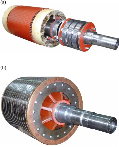
In order to take appropriate measures to avoid these mains reactions, two drive configurations are investigated. First, an induction machine with slip ring rotor (Fig. 1a) and rheostat in the rotor circuit is presented. Second, a speed controlled induction machine with squirrel cage rotor (Fig. 1b) is compared.
A. Slip Ring Motor with Rotor Rheostat
A motor not being supplied by an inverter causes high starting currents due to the low locked rotor impedance of the induction motor [1]. For a slip ring motor (Fig. 1a), simple measures can be taken to reduce starting currents and to improve the torque speed characteristic. The improved torque speed characteristic (Fig. 4) diminishes the reactions of the load impulses on the motor currents and voltage sags, since part of the energy of a load impulse is absorbed by kinetic
Manuscript received April 8th, 2009.
H. Kapeller, A. Haumer, C. Kral and C. Grabner are with the Austrian Institute of Technology (AIT), business unit Electric Drive Technologies, Giefinggasse 2, 1210 Vienna, Austria, (corresponding author to provide phone: +43(5)0550-6219; fax: +43(5)0550-6595; e-mail: [email protected]).
energy. After the load impulse, speed is increased and the resulting load current is homogenized.
The disadvantages of a slip ring motor, especially with additional resistances in the rotor circuit, is the deterioration of efficiency due to additional losses in the external rotor resistances and the high abrasion of the brushes, which causes increased deposit of brush dust in the motor. This brush dust subsequently increases the risk of isolation breakdown and causes higher costs of maintenance.
(a)
(b)
Figure 1: (a) slip ring rotor and (b) squirrel cage rotor Instead of a slip ring motor with additional rotor resistances, a speed controlled inverter drive with squirrel cage motor can be used (Fig. 2).
Investigation of the Operational Behavior of a
Large Chipper Drive
[image:1.595.304.543.326.622.2]B. Speed Controlled Squirrel Cage Motor with Inverter A speed controlled drive consists of the electric motor, the power converter, cascaded current and speed controller, the power supply, the mechanical load, the current and speed sensors respectively [2]. The speed controller determines the reference stator current of the machine according to the deviation of the actual speed from the reference speed. The current controller observes limitations of the stator current to avoid overloading the drive. Both, controlling the speed as well as limiting the currents, lead to efficiency savings over a wide operating range and indicates an advantage compared to the slip ring motor. Investment costs are higher due to the additional inverter, but maintenance costs are lower than for the slip ring motor drive, however.
Figure 2: Layout of a speed controlled drive C. Technical Data
The technical parameters of the power supply and the slip ring motor as well as the squirrel cage induction machine are summarized in Tab. 1–3.
II. SIMULATION MODELS
For performing simulations the software tool Dymola is used. Dymola is based on the modeling language Modelica [3]. The Modelica Association not only develops the language specification but also provides the comprehensive Modelica Standard Library (MSL). Except for the inverter and its control all models can be taken from this library.
Based on the Machines library [4] the SmartElectricDrives (SED) library [5] provides models of electric drives using different control structures and strategies.
The SED library contains models of the components used in recent electric drives: sources (batteries and a PEM fuel cell), converters (ideal and power balanced), electric loads, process controllers, sensors, etc. Two classes of drive models are provided:
For fast simulations focused on energy consumption or the efficiency of a drive configuration, the models of the QuasiStationaryDrives can be used. These models neglect all electrical transients in the machines, i.e. they calculate quasi-stationary points of operation, but mechanical transients are considered, however. This enables a remarkably shorter simulation time due to the simpler controller configuration and the neglect of switching effects.
For the analysis of electric transients the TransientDrives have to be used. By choosing this higher level of detail the user has to provide more parameters, besides the fact that these models consume more computing time.
[image:2.595.52.293.230.350.2]Additionally to all elementary components that give the user the freedom to design an entire controlled drive, ‘ready to use’ models are provided. These models can be used to conveniently and quickly arrange simulations [5]. The ‘ready to use’ models contain the machine, the converter, measurement devices and a field oriented control (FOC). Table 1: Grid data
Mains supply
Frequency 50 Hz
RMS voltage, line-to-line 6000 V
Short-circuit apparent power 50 MVA
Short-circuit power factor 0.05
Transformer's nominal apparent power 1.8 MVA Transformer's short-circuit p.u. voltage 0.06 Transformer's copper losses 17.5 kW Table 2: Parameters of the investigated chipper drive with slip ring motor
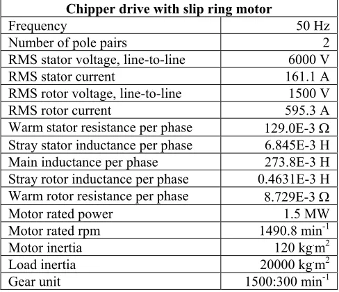
Chipper drive with slip ring motor
Frequency 50 Hz
Number of pole pairs 2
RMS stator voltage, line-to-line 6000 V
RMS stator current 161.1 A
RMS rotor voltage, line-to-line 1500 V
RMS rotor current 595.3 A
Warm stator resistance per phase 129.0E-3 Ω Stray stator inductance per phase 6.845E-3 H Main inductance per phase 273.8E-3 H Stray rotor inductance per phase 0.4631E-3 H Warm rotor resistance per phase 8.729E-3 Ω
Motor rated power 1.5 MW
Motor rated rpm 1490.8 min-1
Motor inertia 120 kg.m2
Load inertia 20000 kg.m2
Gear unit 1500:300 min-1
Table 3: Parameters of the investigated chipper drive with low voltage inverter supplied squirrel cage motor
Chipper drive with squirrel cage motor
Frequency 50 Hz
Number of pole pairs 2
RMS stator voltage, line-to-line 690 V
RMS stator current 1404.5 A
Warm stator resistance per phase 1.702E-3 Ω Stray stator inductance per phase 0.10835E-3 H Main inductance per phase 4.063E-3 H Stray rotor inductance per phase 0.10835E-3 H Warm rotor resistance per phase 1.135E-3 Ω
Motor rated power 1.5 MW
Motor rated rpm 1493.9 min-1
Motor inertia 80 kg.m2
Load inertia 20000 kg.m2
Gear unit 1500:300 min-1
speed controller current controller + + power controller squirrel
cage motor load reference speed reference current power supply current sensor position transducer d/dt I I current feedback
[image:2.595.305.549.329.539.2] [image:2.595.305.549.577.763.2]A. Slip Ring Motor with Additional Rotor Resistances An external rotor resistance can be used to increase the impedance of a slip ring motor (Fig. 3). This measure allows to reduce starting currents and improves the torque speed characteristic (Fig. 4).
Figure 3: Three phase rheostat of a slip ring induction motor The total rotor circuit resistance Rr∗ consists of the internal rotor winding resistance Rr and the external resistance, which
in turn is built up from a variable rheostat Rv and an external
constant resistance Rc:
c ν r
r R R R
R∗ = + + . (1)
Starting from stand still, the resistance of the rheostat Rv is
[image:3.595.306.546.373.623.2]reduced along a linear time dependent ramp. The duration of the ramp has to be chosen according to the drive configuration to meet the actual starting time. After reaching nominal speed, the rheostat Rv is shortened.
Figure 4: Stationary torque versus speed characteristic of a slip ring motor with external rotor resistance
Figure 5: Stationary current versus speed characteristic of a slip ring motor with external rotor resistance
If the motor is not loaded, the influence of the constant resistance Rc on the motor current and speed can be
neglected. Applying a constant load torque the stationary speed depends on the actual resistance Rc according to the
following equation
c c r r
s R R s
R +
= , (2)
where s denotes the slip for the case without external rotor circuit resistance, and sc is the slip for the case with the
external rotor circuit resistance Rc [6].
The impact of the external rotor resistance Rc on the
torque-slip characteristic is shown in Fig. 4: The same torque is delivered at higher slip, i.e. lower speed. Therefore, load impulses can be absorbed temprorarily by the stored energy of all rotating masses. However, the speed dip is compensated after the load pulse.
The characteristic of stator current versus speed is shown in Fig. 5. For a shortened slip ring rotor (Rr∗ =Rr) the torque speed characteristic shows a very low starting torque and a starting current of approximately 5 times the nominal current. For higher external rotor resistances, e.g. Rr∗ =21Rr, the stationary characteristics show a much higher starting torque - close to the breakdown torque - and the locked rotor current is less than 4.5 times the nominal current, decreasing rapidly with increasing speed.
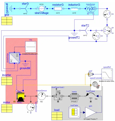
[image:3.595.69.278.391.549.2]Figure 6: Modelica model of the chipper drive with slip ring motor
[image:3.595.79.278.592.750.2]In order to be able to show root mean square (RMS) values of the voltages and currents in the simulation results, an RMS voltmeter and amperemeter are connected. Additionally, an electrical power sensor measures the active and reactive power consumption of the drive. The stator winding of the slip ring induction motor (AIM) is star connected, connecting the stator terminals to the mains impedances. The rotor windings of the slip ring rotor are star connected, too. The terminals of the slip rings are series connected to the external constant resistor (Rc) and the variable rheostat (Rv). For simplifying the simulation model depicted in Fig. 6, the variable resistor is controlled by a ramp during the start-up of the motor.
The signal inputs of the variable resistor model, however, could be controlled by any other strategy as well, e.g. dependent on current or speed.
A torque and a speed sensor provide signals for the simulation result. The mechanical power of the induction motor is transmitted through a gear (idealGear) to the load inertia and a simplified load torque model (loadTorque). The signal input of the load torque model is commaned by a time dependent table (loadTable) where the cycle of load impulses is stored.
[image:4.595.308.543.47.294.2]B. Speed Controller Squirrel Cage Motor with Inverter Fig. 7 shows a squirrel cage induction motor with a speed controller, using components from the SED library. The voltage supply and electric measurement is the same as in the slip ring motor model, except that a transformer is used to provide 690 V from the 6 kV grid to the low voltage drive. The transformed supply voltage (transformer) is rectified (diodeBridge) and provides the intermediate circuit voltage for the inverter. The rectifier model does not take into consideration switching effects, i.e. the typical non-sinusoidal waveform of a diode bridge. Therefore the supply current is rather comparable to that of an IGBT rectifier. The DC/AC-inverter which is implemented in the field oriented controlled QuasyStationaryDrive model (AIMfoc) feeds the squirrel cage motor model. The mechanical load model is the same, however.
The cascade control system shown in Fig. 2 can be parameterized separately [7] for the speed and the current controller. Starting from the current control loop to the speed control loop, various parameterization methods can be applied to achieve the desired dynamic behavior [8].
Fig. 8 shows the full transient Modelica model of a speed controlled chipper drive with a squirrel cage induction motor. Again, this drive uses components from the SED library. The voltage supply and electric measurement is the same as before, but an ideal switching diode rectifier is uitlized. Additionally, the machine inverter is modeled in detail, not being integrated in the drive model. The model of the ideal switching inverter leads to a high number of switching events during simulation, and therefore causes a significantly longer simulation time.
The mechanical time constants are significantly greater than the electrical time constants. If current peaks due to inverter switching are not of interest for this investigation, the QuasiStationaryDrive model can be used to save a significant amount of simulation time.
Figure 7: Modelica model of a speed controlled chipper drive with a squirrel cage motor
Figure 8: Full transient Modelica model of a speed controlled chipper drive with a squirrel cage motor
III. SIMULATION RESULTS
[image:4.595.307.546.348.601.2]Figure 9: Load response of the slip ring motor and wave form of the modeled load impulses
Figure 10: Stator phase current during start-up and during periodic loading of the chipper drive with slip ring motor
A. Slip Ring Motor
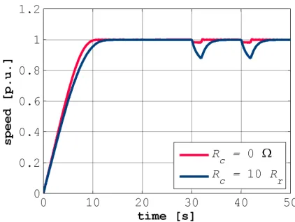
Simulation results for the chipper drive with slip ring motor are shown in Fig. 9–12. Rc = 0 Ω and Rc = 10Rr were set for
two consecutive simulations. The duration of the linear ramp for decreasing the variable resistor (Rv,max = 40Rr) was set to
10 s. Fig. 9 and 10 show that the torque and current get reduced due to the additional resistances in the rotor circuit. From Fig. 11 it is evident, that furthermore the maximum voltage sags at the motor terminals get reduced. Figure 12 shows that a higher external rotor resistance leads to larger speed drop during the load impulses, and it takes some time after the load pulse until the motor has re-accelerated the whole drive to full speed again.
B. Squirrel Cage Motor
[image:5.595.325.536.273.432.2]Simulation results for the chipper drive with squirrel cage motor are shown in Fig. 13–16. The current controller limits overloading of the machine, which can be seen in Fig. 13 and 14. Additionally, during the start up procedure the current limitation of the speed controlled drive is more effective than of the slip ring drive. The voltage drops during load impulses are less than 2 % (cp. Fig. 15). Figure 16 illustrates, that the speed drop during the load impulses shows a similar dynamic characteristic as the chipper drive with slip ring motor.
Figure 11: Stator phase voltage during start-up and during periodic loading of the chipper drive with slip ring motor
Figure 12: Speed during start-up and during periodic loading of the chipper drive with slip ring motor
IV. CONCLUSIONS
Two different designs of a large chipper drives were modeled in Modelica. The first drive consists of a slip ring motor with external rotor resistances, the second drive is a speed controlled squirrel cage motor fed by an inverter. Both drives provide a reduction of current peaks and voltage dips during the start-up and the load pulses.
Using a slip ring induction motor, the investment costs for the motor are higher than for an induction motor with squirrel cage, but the rather simple additional equipment leads to low total investment costs. Disadvantages of the slip ring motor drive are the deterioration of efficiency due to additional losses in the external rotor resistance and the abrasion of the brushes, which gives rise to an increased deposit of brush dust in the motor.
[image:5.595.68.280.273.432.2]Figure 13: Load response of the speed controlled squirrel cage motor and wave form of the modeled load impulses
Figure 14: Stator phase current during start-up and during periodic loading of the speed controlled squirrel cage motor
REFERENCES
[1] P. L. Alger, Induction Machines. New York: Gordon and Breach Science Verlag, 1970.
[2] S. Nasar and I. Boldea, Electric Machines; Dynamics and Control. 2000 Corporate Blvd, USA: CRC Press, 1st ed., 1993
[3] P. Fritzson, Principles of Object-Oriented Modeling and Simulation with Modelica 2.1. Piscataway, NJ: IEEE Press, 2004.
[4] C. Kral and A. Haumer, Modelica Libraries for Dc Machines, Three Phase and Polyphase Machines. Modelica Conference, 549-558, 2005.
[5] H. Giuliani, C. Kral, J.V. Gragger and F. Pirker, Modelica Simulation of Electric Drives for Vehicular Applications. The Smart Electric Drives Library. ASIM, 2005.
[6] R. Fischer, Elektrische Maschinen. München: C. Hanser Verlag, 5 ed., 1983.
[image:6.595.75.274.64.219.2][7] O. Föllinger, Regelungstechnik. Heidelberg: Hüthig Verlag, 8th ed., 1994.
Figure 15: Stator phase voltage during start-up and during periodic loading of the speed controlled squirrel cage motor
Figure 16: Speed during start-up and during periodic loading of the chipper drive with speed controlled squirrel cage motor
[image:6.595.326.537.273.433.2] [image:6.595.68.279.274.432.2]