Abstract— Separation of specific cells from blood stream using paramagnetic/superparamagnetic beads has gained more and more importance in recent times for early diagnosis of several critical diseases. However, the performance immunomagnetophoretic cell sorters (ICS) crucially depends on the design and operational conditions of such, commonly microfluidic, systems. Here, we present a CFD model relying on the Navier-Stokes equations governing the fluid dynamics and continuum descriptions of cell, bead and cell-bead complexes. The spatial-temporal evolution of the concentration fields are governed by convection-diffusion equations for non-magnetic cells and Nernst-Planck type equations for beads and cell-bead complex. The ‘reaction’ rates between cells, cell-bead complexes and beads are deduced from the collision probabilities which are derived by means of classical scattering theory. The CFD model is used to investigate the performance of a generic continuous cell separation system. Since the cells are larger in diameter, more than one bead can get attached to the cells. Multiple beads binding to the cell has been considered in this study, which has not been reported in literature till date. The derived CFD model facilitates the design of ICS taking a realistic description of the binding kinetics into account. Exemplarily, we investigate the performance of Y shaped geometry used for contacting of cells and beads.
Index Terms—BioMEMs, cell capture, CFD, magnetophoresis.
I. INTRODUCTION
Immuno-magnetic separation of rare cells has gained importance in bio-medical applications, primarily for early diagnosis of various types of serious diseases, for isolation of cells for genetic and immunological studies as well as for regenerative medicine. The process involves mixing nano or micro sized ferromagnetic, paramagnetic or superparamagnetic beads coated with antibodies having affinity for a specific type of antigens on the surface of the cell, with a fluid sample containing the cells. Finally a magnetic field is applied to separate the beads and cell-bead(s) complexes. As the volume of sample to be handled is typically very small, designing and fabrication of such microdevices is difficult and continuous efforts are being made to improve upon these to make them suitable for use in lab-on-chip. A number of state-of-art reviews have
Manuscript received June 18, 2008. This work was supported by DFG-Forschergruppe FOR 516/1[0].t Swati Mohanty acknowledges Alexander von Humboldt Foundation, Bonn, Germany, for granting her Research fellowship.
Swati Mohanty is with the Institute of Minerals and Materials Technology (C.S.I.R.), Bhubaneswar, 751013, India (phone: +91-674-2581635 Ext. 235; fax: +91-674-2581637; e-mail: [email protected]).
Tobias Baier is with Institut für Mikrotechnik Mainz GmbH, 55129 Mainz, Germany. (e-mail: [email protected]).
Friedhelm Schönfeld is with Institut für Mikrotechnik Mainz GmbH, 55129 Mainz, Germany. (e-mail: [email protected]).
appeared in literature [1,2], which discuss the application of magnetic force for manipulation of cells and magnetic beads in a microfluidic device. Several designs of micro immuno-magnetic cell sorters (ICS) have been reported and research is on to improve upon these for use in a continuous process. Continuous process has distinct advantage over the batch process as it can be integrated into a lab-on-chip system more easily, has high throughput and can be better controlled. Inokuchi et al [3] propose a design for an on-chip separation of stem cells from peripheral blood. The mixing is first carried out in a laminated chaotic micro-mixer where the magnetic beads get attached to the target cells and then the cell-bead mixture and a buffer fluid are fed into a separator through two different inlets. The target cells captured by the magnetic beads migrate to the top buffer layer due to the applied magnetic field generated by the magnetic coil. Choi et al [4] propose a glass microchip with micro-channels and semi-encaspulated spiral electromagnet for efficient separation of target cells. Pekas et al. [5] designed a hybrid micromagnetic–microfluidic structure which exerts both repulsive and attractive forces at microscale for better diversion of the target particles. Xia et al [6] have designed a micro device in which a high gradient magnetic field concentrator is integrated into the microfluidic channel. Target particles are efficiently pulled from one fluid lamella to the other, flowing parallel to each other. The targeted particles are continuously drawn out as a separate stream preventing accumulation in the micro device and allowing continuous operation. A continuous cell sorter designed by Inglis et al. [7]consists of a magnetic strip integrated to the microchannel so that the captured cells flow in the direction of the magnetic strip rather than the direction of the main fluid flow.
Mathematical modelling helps to achieve an optimal design of any device with minimum number of experiments. Several mathematical models for micro-separators have been reported in literature. In general, all the models assume that there is no interaction between the particles and no body force on the fluid. Pekas et al. [5] have used the equation of motion, taking into consideration the magnetic and viscous drag forces, to predict the particle trajectory in a hybrid repulsion-attraction microseparator. Smistrup et al. [8] have simulated a microfluidic channel with planar spiral micro-electromagnets to predict the flow profile of the fluid using Navier-Stokes equation without the inertial terms and the particle trajectory using the Newtons equation of motion taking into consideration the viscous drag force and the gravity force. Kinetic modelling of interaction between cells and magnetic beads has been reported by Deponte et al [9] considering that only one bead gets attached to each cell. Kim et al. (2008) have experimentally studied a continuous separation of T lymphocytes from biological suspensions.
CFD Modelling of Cell Capture in BioMEMs
Moreover, binding probabilities are computed. A sample stream containing target cells and a buffer stream containing magnetic beads flow side by side in a single channel. A first magnet pulls the magnetic beads into the sample stream and a second magnet further downstream pulls the beads-cell complexes back into the buffer stream such that the target cells are separated from the original sample stream. Mikkelsen and Bruus [11] have studied the motion of paramagnetic beads in a microfluidic device in the presence of a magnetic field using continuum approximation.
However, there is a lack of a suitable model for predicting the cell capture and the flow of different species in continuous micro-magnetic sorters, particularly when possibly more than one bead gets attached to each cell. In this paper we present a hydrodynamic and magnetophoretic model which explicitly accounts for binding kinetics for the formation of cell-bead complexes and which can easily be integrated into a computational fluid dynamics (CFD) code. We apply the model for a specific application of continuous magnetic cell sorting considering a generic microfluidic geometry used for continuous cell sorting. The model allows predicting the concentration profiles of the unbound cells, beads and cell-bead(s) complexes. In this way, the model facilitates to design a device which can efficiently separate the target cells from complex mixtures. Moreover, the simulation methods could be used to deduce details of the binding kinetics from experimental data.
II. GEOMETRY AND MECHANISM
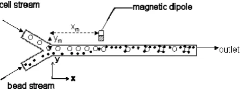
In the present study we investigate immunomagnetic tagging of cells in a Y-channel which is probably one of the most often used microfluidic geometries. The Y-shaped micro-channel under study has a length of 1.12 cm, width of 0.1 cm and a depth of 0.01 cm. Two streams containing beads and the target cells are fed into the reaction channel from two separate inlets as shown in Fig. 1. An external magnet, which is placed within a certain distance from the channel pulls the magnetic beads into the sample stream where cells and beads collide and immunological tagging of the target cells takes place. Due to the antibody-antigen reaction, the beads get attached to the cells, which is assumed to be irreversible.
[image:2.595.53.291.647.735.2]As the cells are typically much larger than the beads, more than one bead can get attached to a single cell. However, the bead can get attached to the cell only if it comes in contact with the free surface of the cell.
Figure 1. Schematic diagram of the modeled microfluidic device for cell capture.
bead to one cell.
III. MODEL EQUATIONS
A three dimensional model was developed based on the following assumptions: The cells and the beads have been treated as continuum. The flow of both streams is laminar. The collision between a bead and a cell results in attachment of the bead to the cell with a certain probability, which is assumed to be constant. The sedimentation of the cells and the beads is negligible. The external magnetic field is created by a magnetic dipole. The fluid is a Newtonian fluid and the properties are same as that of water. The fluid flow is not affected by the beads or cells, but the fluid has an influence on the motion of the cells, beads and cell-bead(s) complex, i.e., a one-way interaction has been considered. Note, basically all the assumptions are made in order to focus on the essential aspects of simulating immuno-magnetic cell capture. The developed model can straightforwardly be expanded to account for more complex binding kinetics, sedimentation, arbitrary magnetic fields and two-way coupling between particle and fluid motion.
Because of the small time constant associated with movement of micro particles in water, acceleration phases can safely be neglected [15]. Thus, it is assumed that the cells have the same velocity as the fluids and beads as well as cell-bead(s) complex have a velocity equal to that of fluid plus an additional velocity contribution due to the magnetic force. The Navier- Stokes equations for incompressible fluid is used to model the fluid phase neglecting any body force resulting from the magnetically induced relative motion of particles. The unsteady state continuum model for the fluid phase can therefore be written as:
u P u
) . u ( t
ur=− r∇ r− 1∇ + ∇2r
∂
∂
υ
ρ
. (1)The continuity equation is given as:
0
=
⋅
∇
u
v
, (2)where,
u
r
, is the velocity vector of the fluid, ν, the kinematic viscosity of the fluid, P is the pressure and ρ, the density of the fluid.velocity there is a possibility of attachment of more than one. Generally, the binding efficiency can be expected to be less than the collision rate, i.e. not every collision necessarily leads to a binding event. Assuming a binding efficiency of p, the rate of binding rate between beads and cells and beads and cell-bead(s) complexes can be written as:
CnB B CnB B CnB B
n
p
C
C
(
r
r
)
w
w
R
=
π
+
2−
, (3)
where, n = 0, N-1, wB denotes the velocity of the beads
and wCnB , the velocity of the cells with n beads attached.
The average radius of a cell with n beads attached is calculated as: 3 1 3 3 / B C CnB (r nr )
r = + . (4)
As stated above all particles are assumed to be convected with the fluid flow and possible have an additional velocity component due to the external magnetic field. For simplicity we assume a permanent magnet and model the induced magnetic field (
B
r
), using a dipole approximation in cylindrical co-ordinates [14]:)
ˆ
sin
rˆ
cos
(
r
m
B
θ
θ
θ
π
μ
+
=
2
4
3 0r
, (5)where, m is the magnetic moment, μ0 is the permeability
constant, r is the distance from the magnet,
rˆ
and θˆ are unit vectors. The magnetic moment is given by,0
μ
/
V
B
m
=
i , (6)where Bi is the intensity of the intrinsic or remanent
magnetic field. For a Nd-Fe-B permanent magnet, Bi is given
as 1.4 Tesla [10]. Assuming that there is no other magnetic material around, the external magnetic field,
H
r
can be written as:0
μ
/
B
H
r
=
r
. (7)For a paramagnetic bead, the force acting on the bead due to the external magnetic field can be written as [15].
H
)
.
H
(
r
F
r
Br
∇
r
+
=
3
2
0 3χ
χ
πμ
, (8)where, χ is the magnetic susceptibility of the bead material and rB is the radius of the bead.
The velocity of beads or cell-bead(s) complex due to magnetic field, vmnB, can be obtained by equating the drag
force with the magnetic force [14]. The drag force exists due to the difference in the velocity of fluid and the magnetic particle. Neglecting velocity gradients in the fluid and hydrodynamic particle-particle interactions we use the Stokes formula for a particle of radius r’ moving with a velocity v in a stationary fluid:
v
r
F
drag=
6
πη
′
. (9)In the case of the magnetic force is balanced by the drag force on the beads or cell-bead(s) complexes. Thus from Equations (8) and (9) we get,
2 3
0
3
3
r
H
r
n
v
CnB B mnBr
∇
⎟⎟
⎠
⎞
⎜⎜
⎝
⎛
+
=
χ
χ
η
μ
. (10) Within the continuum approximation cell transport isgoverned by the time dependent convection-diffusion equation : 0 2
R
C
)
.
u
(
C
D
t
C
C C CC
=
∇
−
∇
−
∂
∂
r
. (11) The reaction terms R0 accounts for the loss in the cell
concentration since cells and beads ‘react’ to cell-bead complexes, cf. Eq. 3.
For the bead concentration the transport equation has to be augmented by the flux resulting from the external magnetic field:
∑
− =−
∇
−
∇
−
∇
=
∂
∂
1 0 2 N n n B B B B B BR
)
F
C
.(
b
C
)
.
u
(
C
D
t
C
r
r
. (12) Moreover the reaction term accounts for the loss in bead concentration due to all possible reactions with cells and cell-bead complexes.
The cell-bead(s)-complex concentrations obey the same equation, except that the ‘reactive’ loss is restricted to the binding reaction CnB+bead →C(n+1)B and additional new species are created via the reaction
CnB bead
B n
C( −1) + → :
n n CnB CnB CnB CnB CnB CnB
R
R
)
F
C
.(
b
)
u
C
.(
)
C
(
D
t
C
−
+
∇
−
∇
−
∇
=
∂
∂
−1 2r
r
(13)where Rn is defined in Eq. 3 and the reaction cascade is
terminated by setting, RN=0, n is the number of beads
attached to a cell and N is the maximum number of possibly attached beads. Generally, CC,, CB and CCnB, denote the concentrations of the cells, beads and cell with n bead(s) per unit volume, respectively. DC, DB, and DCnB, are their
respective diffusivities. N is maximum number of beads attached to a cell and n is the number of beads attached to the cell. The parameter bi, denotes the particle mobility and is
defined as,
η
π
i ir
b
6
1
=
(14)where, i, stands for cell, bead or cell-bead(s) complex. The following boundary conditions were applied to solve the model equations:
At the inlet: CB =CBi; CC = CCi , CCnB=0,
u
r
=
u
, velocity normal to the inlet cross-sectionAt the outlet:
∇
C
B=
∇
C
C=
∇
C
CnB=
0
, P= 1 atm (abs). At the wall: No slip
IV. RESULTS AND DISCUSSIONS
The values are much larger than those which for instance result from the Stokes-Einstein equation. For simplification the diffusivities of beads and the cells have been assumed to be equal. The simulations were carried out with different magnet positions. The final position of the magnet was fixed keeping in mind that the minimum number of beads and cell-bead(s) stick to the walls, as it cannot be completely avoided with the geometry chosen for simulation. The model was simulated till a steady state was reached, which was approximately 15 seconds. The fluid velocity profile was obtained by solving Equation (1). The transport Equations (11), (12) and (13) were solved to predict the concentration profile of the cell, bead and cell-bead(s) complexes. Fig. 2 shows the concentration profile of the cell, beads, cell-bead(s) complexes for a steady state condition. It can be seen that as the cells and beads move from the inlet to the outlet, the concentration of the cell-bead(s) complexes increases. The beads and the cell-bead(s) complexes also move faster than the cells due to additional magnetic force. However, after crossing the magnet, the beads and the cell-bead(s) complexes experience a magnetic force in a direction opposite to that of the flow. Hence, it is observed that concentration of the cell-bead(s) complexes is maximum close to the magnet. Cells with more number of beads experience stronger magnetic force, and hence it can be seen that cells with three beads are drawn more towards the magnet than cells with one bead. As the distance from the magnet increases, the magnetic
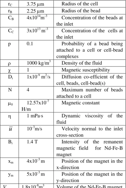
Table I: Parameter values used in the present study rC 3.75 μm Radius of the cell rB 2.25 μm Radius of the bead
CB 4x10¹⁴m-3 Concentration of the beads at the inlet
CC 3x10¹³ m-3 Concentration of the cells at the inlet
p 0.1 Probability of a bead being attached to a cell or cell-bead complexes
ρ 1000 kg/m3 Density of the fluid
χ 1 Magnetic susceptibility
Di 1x10⁻⁹ m2/s Diffusion co-efficient of the cell, beads, cell-bead(s)
N 4 Maximum number of beads
attached to a cell
μ0 12.57x10 -7
H/m
Magnetic constant
η 1 mPa·s Dynamic viscosity of the fluid
u
10-3m/s Velocity normal to the inlet cross-sectionBi 1.4 T Intensity of the remanent magnetic field for Nd-Fe-B magnet
xm 4x10⁻³ m Position of the magnet in the x-direction
ym 5x10⁻³ m Position of the magnet in the y-direction
V 1.8x10⁻⁸m3 Volume of the Nd-Fe-B magnet
forces decreases, and the net velocity towards the outlet increases.
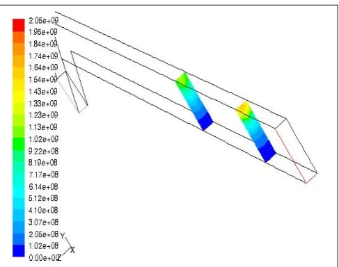
The concentration of the cell-bead(s) complex then increases again. Since it is assumed that the maximum number of beads attached to the cell is four, there is no death of the cell-four-bead complex. So as it moves forward the concentration increases with a maximum at the outlet. For all other cell-bead(s) complexes, the net increase in the concentration depends on the rate of birth and death of the cell-bead(s) complexes. Since 10% binding efficiency has been assumed, the concentration of cell-bead(s) complexes decreases with number of beads attached to a cell. Fig. 3 shows two iso-surfaces in the x-direction for cell-four-bead complex. As the magnet is placed at z=0, the concentration profile shows a maximum at z=0 and gradually decreases in the negative and positive direction of z. It can be seen that the concentration decreases with increasing distance from the magnet.
V. CONCLUSIONS
To the best of the author’s knowledge, this is the first time that an attempt has been made to develop a fluid dynamic model for a continuous immuno-magnetophoretic cell sorters (ICS) taking into consideration binding kinetic and the attachment of more than one bead per cell. The number of beads can be extended to more number of beads attached to a cell, however, the probability will decrease as the free surface available on the cell would decrease. A simple geometry has been chosen initially to simulate and study the flow of the different species in the device. It was noticed that due to magnetic force the beads and cell-bead(s) complexes move towards the wall and their flow is hindered by the wall. The present model can be used to study the flow behaviour of different species in an ICS and design a device so that efficient separation of unbound cells and bound cells can be obtained. This would significantly reduce the number of experiments to be carried out to obtain the best design. Since the beads and cell-bead(s) complexes get deflected towards the magnet, one possibility is to bifurcate the micro-channel into two after crossing the magnet, one which is curved and the other which is straight. The straight channel could be the outlet for the residual cells whereas the curved channel could be the outlet for the beads and the cell-bead(s) complexes. The other possibility would be to use a second magnet in the opposite side of the first magnet, towards the outlet which could pull back the beads and cell-bead(s) complexes. Again, the outlet can be bifurcated to separate out the residual cells and the bead and cell-bead(s) complexes. By simulation, the optimum position of the magnet(s) can be obtained.
(a) (b)
(c) (d)
(e) (f)
Figure 3. Iso-surfaces in the x-direction for cell-four-beads
REFERENCES
[1] M. A. M. Gijs. (2004). Magnetic bead handling on-chip: new opportunities for analytical applications. Microfluid Nanofluid. 1, pp. 22-40.
[2] N. Pamme. (2006). Magnetism and microfluidics. Lab Chip. 6, pp-24-38.
[3] H. Inokuchi, Y. Suzuki, N. Kasagi, N. Shikazono, K. Furukawa, T. Ushida. Micro Magnetic Separator for Stem Cell Sorting System,.Proceedings of the 22nd sensor symposium, Oct. 20-21, 2005, Tokyo, pp 125 – 128.
[4] J-W Choi, T.M. Liakopoulos, C.H. Ahn. (2001)..An on-chip magnetic bead separator using spiral electromagnets with semi-encapsulated permalloy. Biosensors & Bioelectronics. 16, pp. 409–416
[5] N. Pekas, M. Granger, M. Tondra, A. Popple, M.D. Porter. (2005). Magnetic particle diverter in an integrated microfluidic format.
Journal of Magnetism and Magnetic Materials. 293, pp. 584–588. [6] N. Xia, T. P. Hunt, B. T. Mayers, E. Alsberg, G. M. Whitesides, R.
M. Westervelt, D. E. Ingber. (2006). Combined microfluidic-micromagnetic separation of living cells in continuous flow. Biomed Microdevices. 8, 299–308.
[7] D. W. Inglis, R. Riehn, R .H. Austin, J. C. Sturm. (2004). Continuous microfluidic immunomagnetic cell separation. Applied Physics Letters. 85 (21),pp. 5093-5095.
[8] K. Smistrup, O. Hansen, H. Bruus, M. F. Hansen. (2005). Magnetic separation in microfluidic systems using microfabricated electromagnets—experiments and simulations. Journal of Magnetism and Magnetic Materials. 293, pp. 597–604.
[9] S. Deponte, J. Steingroewer, C. Löser, E. Boschke, T. Bley. (2004). Biomagnetic separation of Escherichia coli by use of anion-exchange beads: measurement and modelling of the kinetics of cell-bead interaction. Anal. Bioanal. Chem. 379, pp. 419-426. [10] J. Kim, U. Steinfeld, H.-H. Lee, H. Seidel.“Development of a novel
micro immune-magnetophoresis cell sorter,” The 6th Annual IEEE Conference on SENSORS, Atlanta, pp1081-1084.
[11] C. I. Mikkelsen, H. Bruus. (2005). Microfluidic capturing- dynamics of paramagnetic bead suspensions. Lab Chip. 5, pp.1293-1297.
[12] X. Zhang, R. .H. Davis. (1991) The rate of collisions due to Brownian or gravitational motion of small drops. J. Fluid. Mech.
230, pp 479-504.
[13] X. Zhang, O.A. Basaran. (1995). Electric field enhanced coalescence of liquid drops. Sep. Sci. Tech. 30 (7-9), pp. 1169-1187. [14] http://www.britannica.com/EBchecked/topic/357334
/magnetism.