.6803
DEVELOPING AN MR SAFE CALIBRATION AND
INTERFACE MODULE FOR PNEUMATIC
STEPPER MOTORS
J.M. (Jamie) Janbroers
BSC ASSIGNMENT
Committee:
prof. dr. ir. G.J.M. Krijnen V. Groenhuis,MSc J.K. van Zandwijk,MSc
December, 2019
054RaM2019
1
Abstract
2
List of figures
FIGURE 1:THE REFRACTION OF LIGHT GOING FROM ONE TO ANOTHER MEDIUM.[10] ... 10
FIGURE 2:SCHEMATICAL REPRESENTATION OF (FROM TOP TO BOTTOM) A STEP INDEX MULTIMODE, GRADED MULTIMODE AND A STEP INDEX SINGLE MODE FIBER [10]. ... 10
FIGURE 3:FIVE CONSECUTIVE STATES OF A PNEUMATIC STEPPER MOTOR WITH THE HOUSING (YELLOW), ROD (PURPLE) AND PISTON (RED AND GREEN)(SOURCE:VINCENT GROENHUIS [20]) ... 12
FIGURE 4:SCHEMATICAL REPRESENTATION OF THE PV5211-24VDC-1/8 BY PNEUMATIEKVOORDEEL [21]. ... 13
FIGURE 5:THE SCHEMATIC DESIGN OF THE WHOLE SYSTEM. ... 14
FIGURE 6:A WOODEN PLANK WITH HOLES DRILLED FOR LEDS ... 16
FIGURE 7:ENDSTOP MADE FROM WOOD AND TWO PLASTIC OPTICAL FIBRES ... 16
FIGURE 8:END OF A POF EMITTING VISIBLE LIGHT... 16
FIGURE 9:ATTENUATION OF THE POFHFBR-RUS100Z BY BROADCOM [26] ... 16
FIGURE 10:RELATIVE SENSITIVITY OF THE TEPT5700 PHOTOTRANSISTOR [29] ... 18
FIGURE 11:SAMPLE WITH A LED INSERTED WITH MULTIPLE SAMPLES ON THE BACKGROUND ... 18
FIGURE 12:3D MODELS OF THE SENSOR TO POF, GREEN LED TO POF AND THE RED LED TO POF CONNECTORS. ... 19
FIGURE 13:3D MODEL OF THE ENDSTOP. ... 19
FIGURE 14:AN OBSTRUCTED ENDSTOP FROM THE TOP AND WITH TWO POFS CONNECTED (LEFT) AND FROM THE ENTRANCE OF ONE OF THE POFS WITH ONLY ONE POF CONNECTED ... 20
FIGURE 15:A TAPED FEMALE CONNECTOR WITH A SENSOR AND POF CONNECTED. ... 21
FIGURE 16:VERSION TWO OF BUTTON WITH IN RED THE MODIFIED ENDSTOP, IN BLUE THE BUTTON HEAD, IN GREEN THE OBSTRUCTION STICK, IN GREY THE SPRINGS AND IN BLACK THE BUTTON HOUSING. ... 22
FIGURE 17:TWO VERSION OF THE MOVING BUTTON HEAD WITH ON THE LEFT VERSION 1 AND ON THE RIGHT VERSION 2. ... 22
FIGURE 18:3D MODEL OF THE STATIONARY BUTTON HOUSING (LEFT) AND THE 3D MODEL OF THE MODIFIED ENDSTOP HOUSED INSIDE THE STATIONARY BUTTON HOUSING ... 23
FIGURE 19:THE BUTTON SPRINGS WITH ON THE LEFT VERSION ONE, IN THE MIDDLE VERSION TWO AND ON THE RIGHT AN ALTERATION ON VERSION TWO ... 23
FIGURE 20:THE REALIZATION OF VERSION 1 ON THE LEFT AND VERSION TWO ON THE RIGHT OF THE MR SAFE BUTTON. ... 24
FIGURE 21:THE DESIGN (LEFT) AND REALIZATION (RIGHT) OF THE BUTTON HOUSING WITH INDICATOR LIGHT... 25
FIGURE 22:EXPLODED VIEW OF THE 3D MODEL OF THE SUPPORT CONSTRUCTION WITH IN RED THE BUTTON HUB, IN GREEN THE PILLAR AND IN GREY THE FLOOR. ... 25
FIGURE 23:3D MODEL OF AN ATTACHABLE OBSTRUCTION STICK FOR THE PNEUMATIC MOTOR (LEFT) AND AN ENDSTOP FLOOR (RIGHT). ... 26
FIGURE 24:PNEUMATIC STEPPER MOTOR WITH AN ATTACHED OBSTRUCTION STICK, ENDSTOP FLOOR AND ENDSTOP. ... 26
FIGURE 25:ELECTRICAL SCHEMATICS OF THE RED AND GREEN ALWAYS ON LEDS. ... 27
FIGURE 26:SCHEMATIC REPRESENTATION OF THE CONNECTION OF A LED AND A PHOTOTRANSISTOR. ... 28
FIGURE 27:SCHEMATIC REPRESENTATION OF THE CONNECTION OF THE VALVES. ... 28
FIGURE 28:SCHEMATIC REPRESENTATION OF THE CONNECTION BETWEEN THE VALVES AND THE MOTOR HOUSING. ... 29
FIGURE 29:THE MR SAFE ENDSTOP AND INTERFACE MODULE WITH PERIPHERAL EQUIPMENT. ... 30
FIGURE 30:VOLTAGE MEASUREMENT OF THE PHOTOTRANSISTORS MADE WITH AN ARDUINO UNO WITH IN RED THE RIGHT BUTTON, IN GREEN THE MIDDLE BUTTON, IN YELLOW THE LEFT BUTTON AND IN BLUE THE MOTOR ENDSTOP. ... 31
3
List of tables
TABLE 1: SOME SPECIFICATIONS OF THE ULTIMAKER 2 AND THE ULTIMAKER S5[18][19] ... 12
4
Table of Contents
1 Introduction ... 6
1.1 Problem statement ... 6
1.2 State of the Art ... 6
1.3 Hypotheses ... 7
1.4 Concluding remarks... 7
2 Analysis ... 8
2.1 Positioning concept ... 8
2.2 Information transfer... 8
2.3 Optical fibers ... 9
2.4 Types of optical fibers ... 10
2.5 Build material ... 11
2.6 Pneumatic stepper motor ... 12
2.7 Controller ... 13
2.8 Concluding remarks... 13
3 Design & realization ... 14
3.1 Design of the system ... 14
3.2 Design validation ... 15
3.3 Design optimization ... 17
3.4 Female connectors ... 18
3.5 Button ... 21
3.6 Indicator Light ... 24
3.7 Support construction ... 25
3.8 Pneumatic motor and endstop ... 26
3.9 Connector Hub ... 26
3.10 Arduino connection ... 27
3.11 Whole system ... 29
4 Results ... 31
4.1 Operation of the motor ... 31
4.2 Buttons ... 31
4.3 Link ... 31
4.4 Calibration ... 32
4.5 Concluding remarks... 34
5 Discussion ... 35
5
5.2 POF ... 35
5.3 Endstop ... 35
5.4 Link ... 36
5.5 The whole system ... 36
6 Conclusion ... 37
7 References ... 38
8 Appendix ... 41
6
1
Introduction
MRI (short for Magnetic Resonance Imaging) scanners are used in the hospital to make images of the structures of humans. With these images doctors can gain information. The imaging technique is based on the phenomenon of nuclear magnetic resonance. The MRI machine creates a magnetic field and emits a resonance radio frequency signal for hydrogen atoms. When this frequency is turned off the hydrogen atoms in different molecules can be distinguished. Components that are MR safe can be in an MR environment.
MR safe components are objects that have been tested to demonstrate that it is safe or the objects are made from materials which are considered to be safe with regard to MR environments. Examples of these MR safe materials are plastic, silicone and glass [1].
Medical Robots are developed to be used during surgeries and other medical treatments. Robots can be more accurate than humans. The MR environment of an MRI machine makes it difficult for a traditional robot to operate. Therefore, nontraditional MR safe pneumatic robots are developed. With these robots specific, actions can be done in an MR environment. These robots are made of plastic and other MR safe materials. Air is compressed to transfer energy for the movement of the motors of the robots. Examples of these robots are the Stormram robots and the Sunram robots [2] [3].
1.1
Problem statement
The Sunram robot is designed to take biopsies of a breast in MR environments. Biopsies are crucial for the conformation of a diagnosis. Biopsies without a robot can be less accurate because the biopsy might miss the right location. The robot can be operated in the MRI control room and be guided to the right position. The robot however is operated manually. This is done because the robot has no sensors and therefore cannot detect its own position. An MR safe sensor to detect the position of the robot can be the solution to the position problem and might eliminate the manual control. The robot with the sensor can be directed to the right position at once without manually controlling. This might save time and be more convenient for the user.
The Sunram robot is controlled from outside the MRI room. The robot doesn’t indicate when it is turned on or operating. Communication from the robot to the controller outside the MRI room is also not present. Future applications for the robot might need a button or some indication light to link the controller outside the MRI room with the Robot inside the MRI room.
1.2
State of the Art
MR safe sensors exist. Research has been done and concepts have been made of MR safe sensors. Some sensors for MR environments are commercially available. Below two examples of MR safe sensors are described.
In 2016 a rotary stepper motor with an attachable quadrature position encoder was designed and built by C. Rossides [4]. The encoder operated by sending an optical signal through optical cables and obstructing the light beams by an encoder disc. This encoder disc periodically interrupted the light beam.
7 for this. The absolute position is known when the strip detects this homing area and is then moved out of this homing area. Micronor also offers MR safe and MR compatible rotary encoders [6].
1.3
Hypotheses
An MR safe calibration and interface module for pneumatic stepper motors might be possible to build with optical fibers. The usage of light to transport information over the years has grown [7]. And the application “optical endstop” for a 3D printer is already on the market [8] [9], showing that the calibration of the printhead of 3D printers with the usage of light is possible. The only difference with a 3D printer and an MR safe stepper motor is that in an 3D printer the optical sensor of the endstop can be in the 3D printer itself. The distance that the light has to travel in an MR safe endstop is greater due to the fact that the sensor needs to be placed outside of the MRI room. Due to the speed of light the signal does not have a critical lag. The usage of light in networks such as the internet shows that with for instance optical light carriers, great distances can be overcome.
1.4
Concluding remarks
8
2
Analysis
In order to design and realize an MR safe calibration and interface module some basic understanding of materials and their manipulation need to be known. This chapter is written to inform about materials and the usage of materials for designing and realizing an MR safe calibration and interface module.
2.1
Positioning concept
To calibrate the position of the motor the position has to be determined. Positioning by an encoder can be done inside an MR environment as is discussed in the State of the art. An MR safe rotary encoder can be inconvenient to implement in a linear stepper motors used in the Sunram robot. The linear incremental sensor by Micronor might be able to be used in a calibration system. The size of the sensor and the fact that the design of the sensor can’t be altered, might obstruct the implementation in a next generation of a Sunram robot. A sensor with the sole purpose of detecting the position of a T-29 pneumatic stepper motor is chosen. A sensor built to detect a T-29 stepper motor might be easier to implement in a future generation of the Sunram robot.
Multiple positioning techniques exist. The position of a phone can be determined by radio waves and the usage of satellites (GPS). However, to obtain the information in an MR environment without distorting the MRI machine excludes the usage of electromagnetic radiation. Electromagnetic radiation might distort MRI machine due to the fact that it operates with elector magnetic radiation as well. A Sunram robot is also used inside an MRI machine meaning that direct line of sight from outside the MR environment is not likely which complicates positioning with radio waves.
3D printers use endstops for the calibration of the position of the printhead. Endstops are sensors which need to be touched or a light beam has to be obstructed. When this is done the endstop can send a signal. The position of the printhead of a 3D printer is important. When a 3D printer is turned on it first needs to calibrate the position of the print head. This is done by moving the head to an extreme/maximum position, for example all the way to the left until it hits the endstop. Due to the signal of the endstop, the system knows the position of the head. This is done in all three directions so that the positions in all three directions are known. Due to the stepper motors used in an 3D printer, the position of the printhead is always known after this calibration.
The concept of an endstop is used because the position of the T-29 motor doesn’t have to be measured all the time. After the position of the motor is determined by the endstop, the system can keep track of the position motor. A stepper motor is a motor that only moves in predefined steps meaning that after the detection of the position of the motor the absolute position is known.
2.2
Information transfer
The concept of an endstop means that the stepper motor needs to physically actuate the endstop. Due to the MR safe regulations the endstop cannot be made of electronics and cannot contain copper wire to send signals to outside the MR environment. Other concepts of sending information from one place to another place need to be investigated for designing an MR safe sensor. An MR safe solution for the information transfer from inside to outside the MR environment needs to be chosen. Below some ways of sending information is discussed.
9 the wire might cause friction and the wire itself might act as a spring meaning that there can be lag in the mechanical system.
Another mechanical solution would be a rigid pipe of MR safe material that spans the distance from outside the MR environment, where it is connected to an encoder, into the MR environment. When this pipe is touched in the MR environment the encoder can immediately detect this. Because it is a rigid pipe less lag would occur. A spring needs to be added to move the pipe into its original position after the motor hits the pipe. The construction for such a system might consist friction meaning that there can be lag. Due to the usage of a rigid pipe the system becomes less convenient when the motor is relocated. The pipe might also get in the way in the available space the user has.
Information can also be sent with pneumatics. When a lever in the MR environment is touched, a valve can be opened and air can flow through a tube to the sensor outside of the MR environment. The speed of air in the tube depends on the tube and the pressure on which the systems would run. The tubes can also act as a spring when it is pressurized. Instead of air water can also be used. The disadvantage of water over air is that if it leaks, water is spilling from the tubes which might cause problems with for instance the electronics of the MRI machine.
Another way of sending information is by using optical fibers. When propagation of light through these optical fibers is obstructed the sensor outside of the MR environment detects this. Light in optical fibers don’t travel with the speed of light in a vacuum but with a slower speed. An optical fiber with a
refractive index of 1.492 will have the speed of 𝑣 = 𝑐
𝑛≈ 3⋅108ms
1,492 = 201 ⋅ 10 6 m
s or roughly 67 % of the
speed of light in vacuum. The materials used in the fiber determine the attenuation of light and the flexibility of the fiber.
Due to the speed of light and the flexibility of optical fibers, optical fiber is chosen to be used for the transmission inside the MR environment to outside the MR environment.
2.3
Optical fibers
Before selecting a type of optical fiber, it is important to know how optical fibers work. Optical fibers work with the concept of refraction and reflection. When light travels through the core of the fiber, it can be deflected by material around the core or travel further though the core. The deflection or passing through is described by Snell’s law which can be seen in Equation 1 [10].
𝑠𝑖𝑛𝜃1
𝑠𝑖𝑛𝜃2
=
𝑛2𝑛1 ( 1 )
10 Figure 1: The refraction of light going from one to another medium. [10]
Figure 2: Schematical representation of (from top to bottom) a step index multimode, graded multimode and a step index single mode fiber [10].
2.4
Types of optical fibers
The types of optical fibers are discussed in order to select a type of optical cable for data transmission. There are different types of optical fibers. There are plastic optical fibers (POF) and optical fibers made of glass. An advantage of plastic optical fiber is that the fiber is more flexible than a glass optical fiber [11] [12]. A disadvantage of plastic optical fiber is that the transmission is worse than glass optical fibers. Attenuation, the numerical aperture and other effects cause loss. This is due to material properties of plastic and properties of fiber optics cables in general [13].
11 Multimode fibers can be divided in two categories: Step index fibers and graded index fibers. A step index fiber is an optical fiber with a core with a higher refractive index (n) than the cladding. A graded index fiber is a fiber with a core with a refractive index which scales off relative to the diameter of the core. This means that the light beams in the core can be refracted without hitting the cladding. The cladding has a lower refractive index than the core. This can be seen under “index of refraction” in Figure 2.
A single mode fiber is a fiber with a smaller core than the multimode fibers. Due to this the light beams don’t bounce but travel parallel to the core of the optic cable. A single mode fiber is a step index fiber meaning that the core has a higher refractive index than the cladding.
In order to use a fiber optic cable on or near a robot it might be of importance that the optical fiber is flexible. An MR safe robot like the Sunram 5 can move. At this stadium it is unknown if a next generation of the sun- and Stormram robots are going to have endstops on moving parts of the robots. Therefore, it might be beneficial to use plastic optical fibers. These fibers have generally more attenuation than glass optical fibers but at short distance plastic optical fiber can be used. For the usage of an endstop and buttons the transmission rate of data is not important. One may only push a button five times a second. The type of fiber is therefore not important when selecting a POF.
2.5
Build material
In order to build housing for a sensor or interface module multiple materials can be used. Wood is for instance a material that can be sawed, drilled and sanded into a wanted form. Wood can be precisely cut with a laser cutting machine. The wood processing can take a lot of time and can require a lot of manual processing which acquire wood processing skills.
3D printing is also an option for building housings and parts for the sensor and interface module. 3D printer can print complicated designs without the need for a lot of manual processing. Complicated designs can be printed relatively fast compared with the often slow processing required to acquire the same design with wood. 3D models can be made in computer programs and can be send to a 3D printer. A disadvantage of 3D printing is that simple designs may take longer to print than when the same part is made from wood. Another disadvantage is that overhang can be difficult to print meaning that designs might need to be altered in order to be printable. Support structures can also be printed to support the overhang [17].
3D printing is chosen to be used for building housings and other parts due to the small and complicated designs that might house the optical fibers.
12 Specification\printer Ultimaker 2 Ultimaker S5
Layer resolution 200 μm to 40 μm 600 μm to 20μm 1 XYZ resolution 12.5 μm / 12.5 μm / 5 μm 6.9 μm / 6.9 μm / 2.5 μm
[image:13.595.72.481.73.129.2]Build Volume 223 mm x 223 mm x 205 mm 330 mm x 240 mm x 300 mm
Table 1: some specifications of the Ultimaker 2 and the Ultimaker S5 [18] [19]
.
Figure 3: Five consecutive states of a Pneumatic stepper motor with the housing (yellow), rod (purple) and piston (red and green) (source: Vincent Groenhuis [20])
2.6
Pneumatic stepper motor
In order to control and eventually calibrate the T-29 stepper motor some understanding of the operation of the motor is needed.
The T-29 pneumatic stepper motor is a linear motor that uses the same principle as the pneumatic motors of the Stormram 4 [2]. The motor is made entirely out of plastics meaning that the motor is MR safe. The linear motor contains two pistons and four air chambers (two air chambers per piston). A piston is moved up and down by pressurizing one chamber of the piston and depressurizing the other chamber and vice versa. When two pistons are used and the individual piston have “teeth” that are aligned in a certain way, as can be seen in Figure 3, a rod can be moved left and right. This rod itself also has “teeth”. The step size of the motor is 0.25 mm.
The air chambers can be pressurized by using valves and pressurized air. These valves should be able to pressurize and depressurize the chambers from outside the MR environment. They can be connected with MR safe tubes to the motor. An example of a valves that are able to do this are the PV5211-24VDC-1/8 by Pneumatiekvoordeel. These valves can be opened and closed by a DC voltage of 24 V. In Figure 4 the schematical representation of these valves are shown. In this schematical representation it can be seen that the valve can depressurize and pressurize at the same time. One valve needs to be connected to the air chambers of one of the pistons and the other valve needs to be connected to the chambers of the other piston. Two PV5211-24VDC-1/8 valves by Pneumatiekvoordeel is chosen to be used to control the pistons due to the ability to pressurize and depressurize at the same time.
1 According to the datasheet, Layer resolution of the Ultimaker S5 is dependable on the nozzle. There are 3
nozzles with the following layer resolution: 0.25mm nozzle: 150μm to 60μm, 0.4mm nozzle: 200μm to 20μm,
[image:13.595.82.517.160.265.2]13 Figure 4: Schematical representation of the PV5211-24VDC-1/8 by Pneumatiekvoordeel [21].
2.7
Controller
An Arduino Uno is a microcontroller [22]. An Arduino Uno is programmable and has twelve digitals (IO) pins. These pins can be set to a logical one or zero ( 5 V or 0 V). The amount of current that a pc powered Arduino can deliver is around 400 mA. This can be increased when the Arduino is powered via the DC power jack. The maximum current a single IO pin can produce is 40 mA [23] [24]. When more current or a higher voltage is needed a transistor or an op amp and an external voltage/current source can be used and be controlled via the IO pins.
An Arduino Uno also has six analog input pins. With these pins voltages can be measured up to a voltage of 5V with a resolution of 4.9 mV due to the 10 bit analog to digital converter [25]. The Arduino also has pins with 3 volts and 5 volts which cannot be turned off.
An Arduino is chosen to control the valves due to the multiple pins and the ability to control more than valves. The analog inputs can also be used for voltage measurement of for instance sensors.
2.8
Concluding remarks
The position of the motor will be determined by an endstop. The position will be determined when the motor interrupts a light beam. When the beam is obstructed a signal will be sent to the controller by a plastic optical fiber. The housing of the sensor, interface and other parts will be built by 3D printing. The motor will be controlled by valves. The valves will be controlled by an Arduino.
14
3
Design & realization
With the information given in the analyses a design can be made for the MR safe calibration and interface module. The design and realization of this module is discussed below as well as some tests to validate the design.
3.1
Design of the system
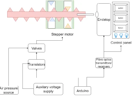
[image:15.595.76.516.226.545.2]The design of the whole system can be seen in Figure 5. The figure shows that the idea was to connect the Arduino to the interface module and the endstop. The valves and thus the motor are also connected to the Arduino. Three buttons and three indicator lights serve as the interface module. The design and realization of the system is further explained below.
Figure 5: The schematic design of the whole system.
An endstop can be created when the opening of two optic fibers are perfectly aligned so that light can travel from one optical cable through the air and then into the second optical cable. This air gap can then be filled with some material that prevents the light from entering the second optical fiber. This way information, for example a logical one when obstructed and a logical zero when the light is not obstructed, can be sent. For this to work some optical fiber and light source needs to be selected so that light can be received after 10 m with a gap of air in between (endstop).
For a button the same idea as for the endstop can be used. The difference is that the button needs to obstruct the light beam when the button is pressed. Indicator light can be created by displaying the end of an optical fiber when the light at the end of an optical cable is strong enough to be seen with the naked eye. Buttons and indication lights can serve as an interface module for the motor.
15 into the MR environment). 5 m is chosen to mimic the distance between MR environment and the non-MR environment. When one endstop of the pneumatic motor and three buttons and three indicator lights are created, the total distance of optical fiber will be 55 m ((4 ⋅ 10 m) + (3 ⋅ 5 m) = 55 m). The total open endings of these fibers will be 22. For this design more than 55 m of POF and 22 connectors need to be obtained. Three buttons and three indicator lights are chosen to be made to create two dedicated buttons and indicator lights for the movement of the motor and one dedicated calibration button and indicator light.
The 100m long HFBR-RUS100Z POF from Broadcom is selected due to its length and price. A compatible connector for this cable is the HFBR-4532Z from Broadcom. This male connector was chosen because it doesn’t contain a metal crimp ring. This connector consists of a latching mechanism so it can latch to a female connector securing the connectors. The male connectors are compatible with the Broadcom transmitters and receivers. These transmitters and receivers can be costly. Especially when seven transmitters and four receivers are needed (one endstop, three indicator lights and three buttons).
Another idea is to use ordinary LEDs as transmitters and phototransistors as receivers. The usage of ordinary LEDs and POFs might be difficult due to the fact that an ordinary LED produces light in different directions meaning that it might be difficult to get sufficient light into the POF to create enough light at the other side of the POF. Attenuation due to the transitions, from LED through air into the POF, from POF through air into another POF (endstop) and from POF through air into the sensor, might also create more attenuation than wanted.
This Idea might be more affordable but might also fail. Therefore, a test is designed to test if it is possible use a led and optical fiber to transmit information through the optical fiber. A summary of this test can be seen below. In the Appendix the full test can be read.
3.2
Design validation
A wooden plank is used as a frame/connector for LEDs, phototransistors and optical fiber. Holes are drilled into the plank with the same dimensions of the LEDs, phototransistor and the optical fiber. This way the fibers and LEDs can fit perfectly in the wooden plank. An example of this can be seen in Figure 6. In the “LED and phototransistor” holes a smaller hole is drilled through the whole plank for an optical fiber. When an optical fiber and a LED is placed in these holes, an attempt is made to emit light into the fiber.
16 Figure 6: A wooden plank with holes drilled for LEDs Figure 7: Endstop made from wood and two plastic optical
fibres
After 5 m of POF visible light was detected by the naked eye, this can be seen in Figure 8. After 5 m of POF, an endstop and then a POF of 1.5 m, there was still light visible with the naked eye. The phototransistor was also tested. With the LED-5 m POF – endstop – 1.5 m POF – phototransistor setup, the light was detectable. The measured voltage difference over the photo transistor (when receiving light and when not) was depended on the colour of the light that the LEDs emitted. When wiggling the fibers near the endstop the alignment of the fibers changed. The light at the end of the fiber changed intensity when this happened.
In conclusion the test showed that a transmission with plastic optical fiber was possible. And detectable with the sensor. There was a lot of loss when the fibers were not right aligned.
Figure 8: End of a POF emitting visible light
[image:17.595.316.536.71.255.2] [image:17.595.73.244.484.730.2] [image:17.595.318.514.488.686.2]17
3.3
Design optimization
In order to make the transmission of light better, multiple things can be done. The source signal (the LEDs) can be made stronger and more directional. This way more light will be sent into the opening of the POF. The datasheet of the POF contains a figure showing the attenuation in dB/km of light with a wavelength between 620 nm and 700 nm. This can be seen in Figure 9. The wavelength of the LED is therefore also important for the attenuation.
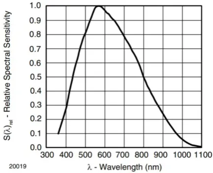
The 520 nm (green) LED MC703-1061 by Multicomp Pro and the 624 nm (red) LED VLCS5830 by Vishay is chosen to be used as transmitters due to the light intensity and the light directionality produced by the LED. The red LED produces 65 cd [27] and the green LED produces 45 cd [28] according to the datasheets. This is more than the brightest LED from the test above. The LEDs are also producing light in one direction resulting in a small emission angle. Smaller emission angles mean that more light will be emitted into the fiber. A downside is that the attenuation of the red LED is high compared to a LED with a bigger wavelength. According to Figure 9 the red LED with a wavelength of 624 nm will be attenuated more due to an attenuation peak that is due to the characteristics of the fiber. Information about the frequency lower than 620 nm is not given by the manufacturer and the exact material of the core is also unknow making it hard to approximate the attenuation of the green LED with 520 nm.
The attenuation of the red light in the above-mentioned optical fiber can be calculated. Figure 9 shows that an attenuation of approximately 460 dB/km Is present at 625 nm. This can also be written down as 0.46 dB/m. This means that the attenuation will be 0.46 dB
m ⋅ 5 m = 2.3 dB at 5 m. 2.3 dB
attenuation results in 10−2.310 = 0.5888 or 59 % of the original power. After 10 m this will be 10 −4.6
10 =
0.3467 or 35 % of the original power.
The transition between LED and POF and between POF and POF can also be improved by sanding and polishing the connectors with a polishing kit. The polishing alone should have approximately a 2 dB improvement of optical power in a transceiver-receiver link [26]. The datasheet hints that without any sanding the attenuation would be worse. This would result in at least an extra 2 dB attenuation. The total attenuation of a 5 m fiber at 625nm would then be 2 dB + 2.3 dB = 4.3 dB. This will result
in at least 10−4.310 = 0.3715 or 37 % left of the original power. The attenuation of two fibers of 5 m will
be 2 dB + 2.3 dB + 2 dB + 2.3 dB = 8.6 dB . This will result in at least 10−8.610 = 0.1380 or 14 % of
the original power. Therefore, the HFBR-4593Z polishing set from Broadcom is selected for the polishing of the fibers/connectors.
18 Figure 10: Relative sensitivity of the TEPT5700 phototransistor [29]
3.4
Female connectors
In order to connect the male connectors of the fibers to the LEDs and phototransistors, a female connector has to be made. Three different kinds of female connectors need to be made. A green LED to fiber, a red LED to fiber and the sensor (phototransistor) to fiber connector.
These connectors can be made by 3D printing. The dimension of the optical fiber connector, LEDs and phototransistor are given in the datasheets. With the dimensions, connectors can be drawn in solid works and then be printed. To make sure that these connectors fit all the components right, samples can be made. an example of these samples can be seen in Figure 11. The sample for the male optical fiber connector does contain a protrusion for the latching mechanism. The samples for the LEDs and the phototransistors also contain a shallow hole for the protrusion of the LEDs and phototransistors to make sure that the whole component is clamped by the sample. The samples are printed with the Ultimaker S5 with tough white PLA.
Figure 11: Sample with a LED inserted with multiple samples on the background
[image:19.595.74.339.485.646.2]19 Figure 12: 3D models of the sensor to POF, green LED to POF
and the Red LED to POF connectors.
Figure 13: 3D model of the endstop.
The sample for the male optical fiber connector can be used when making an endstop. Two of these samples merged together with some space between the samples (earlier discussed airgap) and some material to hold them together can form an endstop. In Figure 13 the model can be seen. To make it possible to interrupt the light beam a 2 mm gap between the two parts was created. Another problem it that a 3D printer is not good in printing overhang. Therefore, the design looks asymmetrical due to added fillets. These fillets make it easier to print.
With the components mentioned above a link (LED -POF-endstop-POF-sensor) can be created. This link can also be tested to see if the brighter LEDs, the polished fiber and the better alignment of the components help improving the propagation of light.
For this test the ordered LEDs are operated on their absolute maximum rating. This means that the current through the red LED was set to 0.05 A and the current through the green LED was set to 0.03 A. The phototransistor is set in series with a 100 k resistor. The voltage of the phototransistor is being measured. 5 V is put over the resistor and the photoresistor. When the sensor detects no light approximately 5 V is measured. When the sensor detects light less than 5 V is being measured
Multiple tests were done but two important observations were done during the following tests
3.4.1
Test 1
[image:20.595.73.327.70.284.2]20
3.4.2
Observations test 1
The first observation before measuring is that the LED to POF connector emits light. This is due to the fact that this connector is printed with tough white PLA. One could see the LED emitting light through the sides of the connector.
The difference between the measurement with a connector on the POF and without a connector on the POF can be seen in Table 2. There is a difference but the link was already decent considering that the voltage over the phototransistor was 4.9 V when the LED was turned off.
Voltage over the sensor 10 m POF 10 m POF with connector
Red LED 28 mV 12 mV
[image:21.595.73.520.450.590.2]Green LED 32 mV 9 mV
Table 2: The difference of a 10m POF link with and without connector and polishing
3.4.3
Test 2
The endstop is being tested. For this test two polished POFs of 5 m, an endstop, a POF to LED connector and a POF to sensor connector will be used in a LED-POF-endstop-POF-sensor link. A measurement of the sensor voltage will be done with the endstop being obstructed and not obstructed. This way the effect of the endstop can be measured. The endstop will be obstructed with a white 3D printed stick that fits into the endstop.
3.4.4
Observations test 2
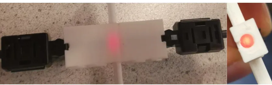
The first observation before measuring is that not only the LED to POF connector emits light but also the endstop. The light also propagates through the white stick meaning that the light is not entirely obstructed by the stick. This resulted a voltage 27.660 mV without obstruction and a voltage of 3.8808 V when it was obstructed. Light propagating through the white PLA can be seen in Figure 14.
Figure 14: An obstructed endstop from the top and with two POFs connected (Left) and from the entrance of one of the POFs with only one POF connected
3.4.5
Other observations
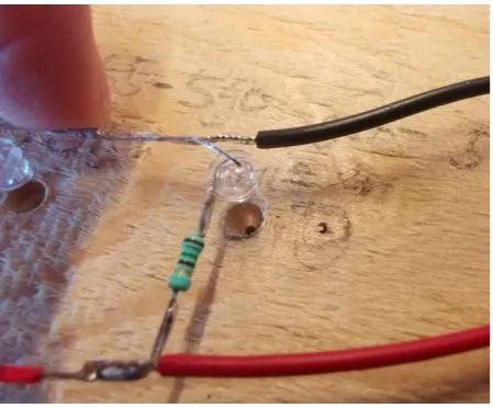
21 Figure 15: A taped female connector with a sensor and POF connected.
After these observations the conclusion was made that the link, with endstop can propagate light on the sensor resulting in a voltage swing of almost 5 V. This voltage swing can easily be detected by an Arduino. This result is a combination between the alignment of all the components, the brighter LEDs and the polishing making the propagation of light from LED to sensor better.
The problems that occurred during the test due to the white tough PLA can be fixed by printing the component with Black tough PLA. The same test was done with the black components. The result can be seen in Table 3. The Black endstop and obstruction stick don’t propagate light into the sensor when the endstop is obstructed.
Without obstruction obstruction
No light was sent 4.777 V 4.821 V
Red LED 29 mV 4.822 V
Green LED 22 mV 4.821 V
Table 3: the measured voltage of a POF-endstop-POF link with and without obstruction
An interface module with three buttons and three lights, a pneumatic motor with the endstop and a connector hub with all the sensors and LEDs so that the POF cables can be easily attached, can be designed with the connectors and endstop as building blocks.
3.5
Button
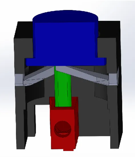
22 Figure 16: Version two of button with in red the modified endstop, in blue the button head, in green the obstruction stick, in grey the springs and in black the button housing.
Figure 17:Two version of the moving button head with on the left version 1 and on the right version 2.
This design would require the following components:
3.5.1
A moving button head
This is the part of the button that moves up and down when the button is pressed. The first version can be seen in Figure 17. The button head was designed so that the protrusion of the button would be 2 mm relative to the Housing. The barb is present so that the button is not pushed out of the housing. In the bottom of the button head a hole is made for an obstruction stick to be clamped in.
3.5.2
A stationary button housing
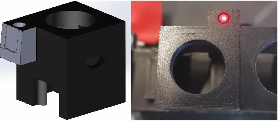
23 Figure 18: 3D model of the stationary button housing (left) and the 3D model of the modified endstop housed inside the stationary button housing
3.5.3
An endstop
To cling the endstop to the housing the surface of the endstop is modified. The design can be seen in Figure 18. In order to print the overhang a fillet has been added (the housing also has a round shape to compensate for a better attachment of the endstop).
3.5.4
An obstruction stick
An obstruction is stick made so that it can be inserted and attached to the head. It remains in the head due to friction.
3.5.5
Spring
The springs should press the button head up when it is not pressed. To make the springs an earlier printed obstruction stick was bent by a human to 2 mm. the length of the stick was altered to see which length was needed to easily bend the stick 2 mm. With this information the design was made. The printed version can be seen in Figure 19. The two springs can be mounted in the housing. Due to the fact that the first printed layer is a bit wider than all the other layers, the springs cannot go through the housing. The first layer works as a barb.
Figure 19: The button springs with on the left version one, in the middle version two and on the right an alteration on version two
24 out with the housing. This means that the obstruction stick would obstruct the light without the button being pressed.
The springs could be improved to prevent the light from being obstructed due to wear. This was a difficult task due to printing with PLA. Other materials were also available but the fact remained that if a spring wears out the button is pressing itself. Therefore, this idea was dropped and the focus was directed at increasing the excursion. The length of the obstruction stick could be chosen so that only when the button is pressed level with the housing (4 mm down), the endstop would be obstructed. This means that there is a 3 mm range when the button is pushed and the endstop is not obstructed. The wear of the springs would have less effect on the obstruction of the endstop.
In order to achieve a 4 mm excursion, all the parts with the exception of the endstop have to change. The Button Head has to be taller so that when the button is not the pressed the excursion is 4 mm instead of 2 mm. The housing also has to be taller so that the attachment hole for the springs is 2 mm down so that the bottom of the button levels the attachment of the springs at 4 mm excursion instead of 2 mm excursion. The springs are made 2 times longer so that the springs bends the same as with the previous version. Due to the lack of room the design of the springs was slightly altered. Two version were made of the new springs and this can be seen in Figure 19. The result of version two of the button can be seen in Figure 20.
Figure 20: The realization of version 1 on the left and version two on the right of the MR safe button.
3.6
Indicator Light
25 Figure 21: The design (left) and realization (right) of the button housing with indicator light.
3.7
Support construction
In order to use the button with indicator light, some kind of housing for the buttons have to be made. A so-called button support construction should hold the buttons at its place and have some elevation so that the fibers for the indicator lights don’t have to be band in a tight corner to be connected to the button. If an optical fiber is bend in a tight corner the fiber could break. The design can be seen in Figure 22. The structure consists of three printable parts. The structure was difficult to print in once due to the overhang.
[image:26.595.73.363.519.732.2]The floor is for the support of the whole structure so that it doesn’t fall when a button is pressed. The floor also contains attachment structures for the fibers to be attached to with for instance tie rips. The tunnel is designed so that the fibers can be held together “entering” button section. The pillar of the construction is designed to elevate the buttons. At the top of the pillar are four protrusions with holes. These holes can be used for mounting the button hub with bolts and tuts. The button hub is a platform with blocks. These blocks are made to cling the button housing. The protrusions at the sides are made to mount the button hub to the pillar. The design can be seen in Figure 22.
26
3.8
Pneumatic motor and endstop
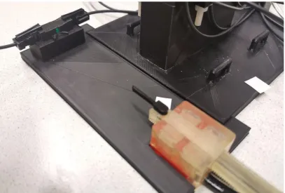
[image:27.595.73.523.243.361.2]The T-29 pneumatic stepper motor needs to obstruct an endstop when the moving rod is nearly out of range for the motor to control. This can be done by attaching an obstruction stick to the moving rod of the motor. This can be done by printing a rod that fits exactly in one of the holes present in the rod of the motor. The design for this obstruction stick can be seen in Figure 23. The endstop and the motor needs to be mounted so that the endstop is obstructed when the motor pushes the rod to one of the two outer limits of the motor. The endstop also has to be aligned with the motor. The design is an endstop floor where the motor and the endstop can be clamped in at the right distance and height. The design can be seen in Figure 23. The floor of the button structure can also be clamped in the floor of the endstop floor. The endstop used is the modified endstops made for the buttons due to the protrusions. The realization can be seen in Figure 24.
Figure 23: 3D model of an attachable obstruction stick for the Pneumatic motor (left) and an endstop floor (right).
Figure 24: Pneumatic stepper motor with an attached obstruction stick, endstop floor and endstop.
3.9
Connector Hub
[image:27.595.72.480.386.661.2]27
3.10
Arduino connection
Four LEDs and four sensors always have to be on to make it possible for the sensors to detect when one of the three buttons is pressed or when the motor is obstructing the endstop. This means that four green LED or four red LED need to be on all the time. These LEDs can be connected via the 5 V connection with the LEDs in parallel. Each LED will have a series resistor to prevent the LEDs from breaking. The resistance of these resistor can be calculated by subtracting the typical voltage drop given in the datasheets from the 5 V supply and dividing this remaining voltage by the wanted current because 𝑈
𝐼 = 𝑅. This results in a
5 V−3.3 V
30 mA = 56.66 Ω series resistor for a green LED and a
5 V−2.2 V 50 mA =
56.00 Ω series resistor for the red LED. This means that the Arduino is always delivering respectively
4 ⋅ 30 mA = 120 mA or 4 ⋅ 50 mA = 200 mA. This is within the earlier mentioned bounds. There are three lights that can be turned on when a button is pushed resulting a total of 7 ⋅ 30 mA = 210 mA
or 7 ⋅ 50 mA = 350 mA in total. The four sensors will act as a closed connection between the collector and emitter (assumed by the measurements) therefore the current will be defined by the series resistor. A 100 kΩ resistor and a source voltage will result in a maximum current of 100 kΩ 5 V = 0.05 mA
through a phototransistor.
In order to be able to choose between red or green LEDs seven red and seven green LEDs are being connected to the Arduino. In Figure 25 the schematics of the four green and four red LEDs which always emit can be seen. A switch is connected so that the user can choose between four green LEDs that are always on or four red LEDs that are always on.
There are also three green and three red LEDs individually connected to the IO pins of the Arduino and can be used for the indicator lights. These LEDs are programmable making it possible to make an indicator light red or green because these LEDs are individual connected to the IO pins. The plastic optical fiber should however be physically in the connector of these LEDs meaning that switching from color without switching the POF into right connector is not possible. The scheme of how a LED is connected to one of the IO pins can be seen in Figure 26.
[image:28.595.77.524.520.735.2]The phototransistors are connected in parallel to the 5 V supply voltage with a series resistor in every branch. The voltage over the phototransistors is measured by the analog input pins of the Arduino. The schematic circuit can be seen in Figure 26.
28 Figure 26: Schematic representation of the connection of a LED and a phototransistor.
The two valves to control the stepper motor are rated for 24 V and 2.8 W. An auxiliary power supply with a supply voltage of 24 V is needed to control the valves since the Arduino doesn’t produce a supply of 24 V. Two TIP 120 transistors can be used as a switch to connect the valves to the 24 V supply voltage. The transistors can be controlled by two IO pins of the Arduino. The electrical schematics of the two valves can be seen in Figure 27.
Figure 27: Schematic representation of the connection of the valves.
[image:29.595.77.380.415.629.2]29 Figure 28: Schematic representation of the connection between the valves and the motor housing.
The Arduino is programmed so that the two outer buttons are used to move the motor up or down. The middle button is used as the calibration button. The motor will try to find the endstop when this button is pressed and when the light of the endstop is obstructed, the motor will stop. The position is also set to zero meaning that the motor can only go away from the endstop when a button is pressed to move the motor. A negative position cannot be reached in order to protect the motor from hitting the endstop. A maximum position is also set so that the motor cannot go too far in the other direction.
3.11
Whole system
31
4
Results
After the realization, the system was tested to see how it performs. The purpose of these tests was to observe the performance. Below the observations can be read in four subchapters: Operation of the motor, Buttons, Link, Calibration.
4.1
Operation of the motor
The motor and endstop works as designed. When the left buttons in Figure 29 is pressed the motor moves the rod down. When the right button is pressed the motor moves the rod up. When the middle button is pressed the motor calibrates itself by moving towards the endstop until the obstruction stick obstructs the endstop (when the Arduino reads more than 3 V over the phototransistor). After this calibration the motor can only be moved down. When the right button is pressed nothing happens. If the motor would move up a collision would occur with the rod of the motor and the endstop. The motor can be moved down until the rod almost disappears in the motor. If the motor moves the rod further than this point the rod would exit the housing of the motor resulting in an unusable motor. The motor can be moved up and down between these maximum positions (all the way up and all the way down).
4.2
Buttons
[image:32.595.70.452.449.682.2]The buttons work and obstruct the light as designed. In Figure 30 a voltage measurement over the sensors is shown. The peaks of the lines show the voltage rise when a button is pressed. The springs of the buttons still wear out in time. Due to the design the springs don’t have to be replaced often. The endstop in the button is not obstructed if the springs wear out. The buttons don’t recover all the way up after they are being pressed. This is due to the wear of the springs and the created extra excursion. After approximately 100 button presses the springs are worn up. Extra springs were made to replace springs that are too broken to be functional.
Figure 30: Voltage measurement of the phototransistors made with an Arduino Uno with in red the right button, in green the middle button, in yellow the left button and in blue the motor endstop.
32 The different links are not ideal. This can be seen in Figure 30. The graph shows that when nothing is pressed the voltages of the different sensors vary from each other. This can be caused due to imperfections of the fiber or imperfections of the alignment of the connectors. All the other components in a link can also be causing this due to the fact that every individual component can always differ from the given characteristics.
The signal created when a button is pressed is well received with a voltage difference of over 1 V. Due to the speed of light in an optical fiber, the signal doesn’t contain lag and thus is not a limiting factor for the speed of the motor and the whole system.
[image:33.595.73.306.320.545.2]Another issue with the link is crosstalk. A LED emits light into a fiber to turn on an MR safe indication light. When this happens a glimpse of this light is also seen in the other indication lights. This is due to the construction of the electronics on the protoboard and the open back of the connectors. In Figure 31 the open back of the connector hub creates an opportunity for light from a LED in the hub to be reflected from the protoboard and go into one of the other connectors. This causes a glimpse of light in other fibers than the intended fiber.
Figure 31: POFs inserted in the connector hub which is connected to LEDs and sensors on a protoboard.
4.4
Calibration
The total system is also tested. A way of looking if the calibration of the motor is accurate, is by measuring the position of the rod of the motor at the maximum positions of the motor after calibration. This is done ten times to see if the calibration positions and the maximum positions change. This test is done with a motor step frequency of 50 Hz and 20 Hz. The stepper motor can skip a step or stall completely when the frequency is too high [20] [2].
Steps of the test:
1. Calibrate the motor. Measure the current position relative to the motor housing.
33 3. Move the motor all the way up until it doesn’t go any further. Measure the position relative to the motor housing.
The results of the measurements can be seen in Table 4 with a step frequency of 50 Hz and in Table 5 with a step frequency of 20 Hz. The positions were measured with a caliper. The current through the valves is also measured. V1 and V2 in Table 4 and Table 5 show through which valve (valve 1 or valve 2) current is sent.
Attempt\ position
Calibration position
V1 V2 Maximum position opposite of endstop
V1 V2 Maximum position at endstop
V1 V2
1 0.60 mm off off 82.30 mm off off 0.60 mm off off 2 0.60 mm off off 82.30 mm off off 0.60 mm off off 3 0.85 mm on off 82.60 mm off on 0.90 mm on off 4 0.90 mm on off 82.65 mm off on O.90 mm on off 5 O.60 mm off off 82.30 mm on on 0.60 mm off off 6 0.60 mm off off 82.30 mm on on O.65 mm off off 7 0.90 mm on off 82.65 mm off on 0.90 mm on off 8 0.90 mm on off 82.65 mm off on 0.90 mm on of 9 0.70 mm off off 82.30 mm on on 0.70 mm off off 10 0.90 mm on off 82.65 mm off on 0.95 mm on off Table 4: Measurement of the position of the rod of a T-29 pneumatic stepper motor at 50 Hz after calibration.
Attempt\ position
Calibration position
V1 V2 Maximum position
opposite of endstop
V1 V2 Maximum position at endstop
V1 V2
[image:34.595.73.524.438.633.2]1 1.20 mm on on 82.80 mm off off 1.20 mm on on 2 1.20 mm on on 82.80 mm off off 1.20 mm on on 3 1.20 mm on on 82.80 mm off off 1.20 mm on on 4 1.20 mm on on 82.80 mm off off 1.15 mm on on 5 1.15 mm on on 82.80 mm off off 1.20 mm on on 6 1.20 mm on on 82.80 mm off off 1.20 mm on on 7 1.20 mm on on 82.80 mm off off 1.15 mm on on 8 1.15 mm on on 82.80 mm off off 1.20 mm on on 9 1.20 mm on on 82.80 mm off off 1.20 mm on on 10 1.20 mm on on 82.80 mm off off 1.15 mm on on Table 5: Measurement of the position of the rod of a T-29 pneumatic stepper motor at 20 Hz after calibration.
34
4.5
Concluding remarks
35
5
Discussion
This chapter is written to discuss the strengths and limitations of the design and realization. Suggestions for improvements of individual parts and the whole system are also given.
5.1
Springs
The springs can be improved so that the wear becomes less. This might be possible my making the springs longer and the excursion the same so that the bending relative to length of the spring becomes less. Less deformation might result in less wear.
The printing orientation can also be altered. The length of the spring is printed in the z direction of the printer. The strength in the length of the spring can be increased when the length of the spring is printed in the x or y direction. This is because the z direction is the weakest direction of a 3D printed part due to the printing lines. The model for the springs possibly has to change to make the spring printable in another orientation.
The material used to print the springs can also be altered. Tough PLA is used for printing but Nylon or CPE could also be used for printing. Also, other MR safe materials could have been used. The spring could have been made by laser cutting or by other material manipulations. Elastics could also be used. The design of the buttons should possibly be changed for the usage of elastics.
The springs are mounted at the sides of the buttons. When all three buttons are in place, the outer springs of the two outer buttons can be seen. These springs move a little out of the button housing when an outer button is pressed because the spring is not hold back by the housing of another button. When placing the spring back into its position the button moves up. This can be obviated by a wall so that the springs can’t be pushed out of the button housing. This is not a problem for the springs of the middle button or the inner springs of the outer buttons because the housing of the buttons are holding the springs at place.
Due to the design of the springs and button housing the springs can be taken out of the housing quickly. The springs can be replaced when broken. The fact that the springs are printable encourages the replacement of the springs when needed.
5.2
POF
The flexibility of the cables makes it possible to relocate the whole system without damaging the system. Nevertheless, POFs with smaller diameters might be needed for an implementation into the next Sunram version. There are optical fibers with more flexibility due to smaller cores or due to not having an outer (protection) mantle. Flexible fibers might come with more moving space for the motors.
5.3
Endstop
The size of the endstop should be made smaller in order to implement in systems with little space. Some motors of the Sunram 5 are smaller than the T-29. Therefore, the Sunram might benefit from smaller endstops. This might be achieved by smaller 3D printed connectors. The size of the endstop is now decided by the size of the male connectors on the fibers. When smaller male connectors are made, smaller female connectors can be made resulting in smaller endstops because an endstop is created by two connectors facing each other.
36 obstruction stick has a reflective surface. This way the Arduino can measure when light from one fiber is reflected in the other fiber with a sensor.
The endstop itself is now stationery and the rod is moving. This can also be changed by implementing the endstop in the motor housing instead of placing it at the end of the scope of the motor as has been done in this report. The rod can also be altered so that it has an absorbing or a hole part instead of an attachable stick to obstruct the light. The always on idea that is used in this report can also be changed by an always off idea meaning that nothing happens until the sensor is hit with light instead of the other way around.
5.4
Link
The LEDs in this concept are always on and when the sensors don’t receive any light the Arduino does an action. When there is some opening in the link through which ambient light can intruding into the link, errors may occur. This can happen when endstops, connectors or the fiber itself is broken or not shielding good enough from the ambient light. A solution to this problem is to oscillate the signal light and use a filter at the receiving side. This way ambient light can be filtered out of the link when it has intruded the link.
5.5
The whole system
The endstop and the interface module can be improved on multiple areas. The buttons can be made more robust by redesigning the springs. The endstops should be improved when implementing it in a future version of the Sunram robot. The robustness of the link can also be improved.
37
6
Conclusion
38
7
References
[1] Shellock R & D Services, Inc. and Frank G. Shellock, Ph.D. , "Information and Terminology for THE LIST," Shellock R & D Services, Inc. and Frank G. Shellock, Ph.D, [Online]. Available:
http://www.mrisafety.com/Terminology.html. [Accessed 04 12 2019].
[2] V. Groenhuis, F. J. Siepel, J. Veltman, J. K. v. Zandwijk and S. Stramigioli, "Stormram 4: An MR Safe Robotic System for Breast Biopsy," Department of Robotics and Mechatronics, University of Twente, Enschede, 2018.
[3] V. Groenhuis, F. J. Siepel, M. K. Welleweerd, J. Veltman and S. Stramigioli, "Sunram 5: An MR Safe Robotic System for Breast Biopsy," Robotics and Mechatronics, University of Twente;
Ziekenhuisgroep Twente; ITMO, Enschede, Almelo, Saint Perterburg, 2018.
[4] C. Rossides, "Design and implementation of a modular,," University Of Twente, Enschede, 2016.
[5] Micronor Inc., "MR343 Encoder," Micronor Inc., [Online]. Available: https://micronor.com/product/MR343/. [Accessed 09 12 2019].
[6] Micronor Inc., "Products," Micronor Inc., [Online]. Available: https://micronor.com/. [Accessed 09 12 2019].
[7] N. Kasteleijn, "Steeds meer glasvezel in de buitengebieden, Randstad blijft achter," NOS, 08 02 2019. [Online]. Available:
https://nos.nl/artikel/2271012-steeds-meer-glasvezel-in-de-buitengebieden-randstad-blijft-achter.html. [Accessed 23 11 2019].
[8] AliExpress, "item:33058784703.html?src=google&src=google&albch=shopping&acnt=494-037-6276&isdl=y&slnk=&plac=&mtctp=&albbt=Google_7_shopping&aff_platform=google&aff_short_ key=UneMJZVf&&albagn=888888&albcp=6459980570&albag=76980386066&trgt=74361285071 4&crea=nl3305878470," AliExpress, [Online]. Available:
https://www.google.com/aclk?sa=l&ai=DChcSEwjK_cHiloHmAhUFqhgKHQe5CIkYABAHGgJsZQ&si
g=AOD64_0QPOL4npI-AEKSffcro4MZu1_fAQ&ctype=5&q=&ved=0ahUKEwiio7viloHmAhWBbFAKHRmhDr0QpysIFg&adu rl=. [Accessed 23 11 2019].
[9] DennisDeal, "products: robotdyn-opto-coupler-optical-end-stop-module-endstop-switch-for-3d-printer-and-cnc-machine-device_1564995," Dennisdeal, [Online]. Available:
https://www.dennisdeal.com/products/robotdyn-opto-coupler-optical-end-stop-module-endstop-switch-for-3d-printer-and-cnc-machine-device_1564995. [Accessed 23 11 2019].
[10] "LibreTexts," 5 6 2019. [Online]. Available:
https://eng.libretexts.org/Bookshelves/Materials_Science/Supplemental_Modules_(Materials_Sc ience)/Optical_Properties/Snell's_Law. [Accessed 21 11 2019].
39 [12] "Blog: Optical Fiber Technology: When to Choose Glass vs. Plastic Fiber," Lumitex, 11 12 2018.
[Online]. Available: https://www.lumitex.com/blog/optical-fiber-technology. [Accessed 23 11 2019].
[13] O. Ziemann, J. Krauser, P. E. Zamzow and W. Daum, Polymer Optical Fibers of Data Communication, Germany: Springer Science & Business Media, 2002.
[14] "Fiber optics," arcelect, [Online]. Available: https://arcelect.com/fibercable.htm. [Accessed 24 11 2019].
[15] I. Bilal, "Reader Transmission Media," Module 8, signal processing and communication, Enschede, 2017.
[16] G. Verkerk, J. Broens, R. Bouwens, P. de Groot, W. Kranendonk, M. Vogelzang, J. Westra and I. Wevers-Prijs, "Elektromagnetisch spectrum," in BINAS, Groningen, Wolters-Noordhoff bv, 2004, p. 19.
[17] Ultimaker BV, "support, generate support," Ultimaker BV, [Online]. Available: https://ultimaker.com/en/resources/52663-support. [Accessed 10 12 2019].
[18] Ultimaker BV, "Ultimaker S5 Installation and user manual original manual v1.8," Ultimaker BV, 2018.
[19] Ultimaker BV, "Ultimaker2 USER MANUAL V2.1," Ultimaker BV, 2019.
[20] V. Groenhuis, F. J. Siepel and S. Stramigioli, "Dual-Speed MR Safe Pneumatic Stepper Motors," Enschede.
[21] PneumatiekVoordeel, "PV5211 datasheet," Pneumatiekvoordeel.nl.
[22] Arduino, "GETTING STARTED | FOUNDATION > Introduction," Arduino, [Online]. Available: https://www.arduino.cc/en/Guide/Introduction. [Accessed 24 11 2019].
[23] Arduino, "Main/ArduinoPinCurrentLimitations," Arduino, [Online]. Available:
https://playground.arduino.cc/Main/ArduinoPinCurrentLimitations/. [Accessed 24 11 2019].
[24] Arduino, "reference/board: Introduction to the Arduino Board," Arduino, [Online]. Available: https://www.arduino.cc/en/reference/board. [Accessed 24 11 2019].
[25] Arduino, "Reference > Language > Functions > Analog io > Analogread," Arduino, 7 2 2019. [Online]. Available: https://www.arduino.cc/reference/en/language/functions/analog-io/analogread/. [Accessed 24 11 2019].
[26] Broadcom Ltd, "HFBR-RXXYYYZ Series (POF) HFBR-EXXYYYZ Series (POF) Plastic Optical Fiber Cable and Accessories for Versatile Link Data Sheet," Broadcom Ltd, 2016.
[27] VISHAY INTERTECHNOLOGY, INC., "High Brightness LED, Ø 5 mm Untinted Non-Diffused Package (datasheet)," VISHAY INTERTECHNOLOGY, INC., 2017.
40 [29] Vishay Intertechnology, Inc., "TEPT5700 Ambient Light Sensor (datasheet)," Vishay
Intertechnology, Inc., 2014.
[30] "Start> Cable, Wire & Cable Assemblies> Fiber Optic Cable," Farnell, [Online]. Available: https://nl.farnell.com/c/cable-wire-cable-assemblies/fiber-optic-cable. [Accessed 24 11 2019].
[31] "Start> Connectors> Fibre Optic Attenuators & Connectors> Fibre Optic Connectors," Farnell, [Online]. Available: https://nl.farnell.com/c/connectors/fibre-optic-attenuators-connectors/fibre-optic-connectors. [Accessed 24 11 2019].
[32] Ultimaker BV, "Software: Ultiaker-Cura," Ultimaker BV, [Online]. Available: https://ultimaker.com/software/ultimaker-cura. [Accessed 24 11 2019].
[33] Maastricht UMC, "Onderzoek epilepsiepatiënten in meest krachtige MRI-scanner," 14 8 2019. [Online]. Available: https://www.mumc.nl/actueel/nieuws/onderzoek-epilepsiepatienten-meest-krachtige-mri-scanner. [Accessed 04 12 2019].
[34] RASPBERRY PI FOUNDATION, "raspberry-pi-4-model-b specifications," RASPBERRY PI
41
8
Appendix
8.1
Test 1
8.1.1
Introduction
Due to the fact that theoretical test set up might differ from the real world the following test is done.
The goal of this test is to see if one can use LED’s to transfer light through a plastic optical fibre with a visible beam of light at the end of the fibre
The goal is to test if a phototransistor is sensitive enough to detect the light coming out of a plastic optical cable.
8.1.2
Analyses
In order to get light through a pof one needs to transmit light into this pof. During this transition from light to air into a pof some loss may occure due to the fact that not al the light coming from the source ( a LED for instance) ends up in the pof. The pof itself is also lossy due to the fact that attenuation of light occurs due to scattering of light caused by local microscopic density variation of the fibre and due to absorption of light [15].
The datasheet of a 1mm pof shows that the attenuation of light with wavelength between 620 - 700 nm is between roughly 150 - 450 dB/Km [26].This can be rewritten as 0.15-0.45 dB/m. This results in the original power ranging between 90 % and 97 %. According to the same manufacturer, the ending of the pof can also influence the attenuation when these endings are not polished. The use of the fine polishing steps results in approximately a 2 dB improvement. When this is not done a 2 dB loss can be expected.
Expecting that the absence of rough polishing is also contributing to some loss, meaning that > 2 dB loss can be expected from an unpolished fibre. A total approximation of the attenuation of a POF of 5 m can be show below:
Attenuation at 650 nm: 0.15 dB/m * 5 = 0.75 dB Attenuation at 700 nm: 0.45 dB/m * 5 = 2.25 dB Unpolished cable end attenuation: >2 dB
This results in a total minimal attenuation of 2.75-4.25 dB. This can also be noted down as 53 % and 38 % of the original power.
8.1.3
Measurement plan
8.1.3.1
Materials
In order to conduct the experiment some materials were used. The following materials were used during this measurement.
Lab materials:
42 Agilent - 33220A 20MHz Function/Arbitrary Waveform Generator
Agilent - 34401A 6 ½ Digit Multimeter
Fibre optic cable:
1 x 5 m 1mm plastic optical cable, “unknown specs” 1 x 1,5 m 1mm plastic optical cable, “unknown specs”
LEDs:
L-9294CGCK - LED, Low Power, Green, Through Hole, T-1 3/4 (5mm), 20 mA, 2.1 V, 570 nm L-9294SYCK - LED, Low Power, Yellow, Through Hole, T-1 3/4 (5mm), 20 mA, 2 V, 590 nm L-9294SECK - LED, Low Power, Orange, Through Hole, T-1 3/4 (5mm), 20 mA, 2.1 V, 601 nm
Resistors 3 x 150 ohm 1 x 100K ohm
Photo transistor
TEPT5700 - Phototransistor, 570 nm, 50 °, 100 mW, 2 Pins, T-1 3/4 (5mm)
Wood
Wooden panel, 9.6cm x 52.5cm x 2.0 cm
Connector
[image:43.595.72.348.533.738.2]1x F495 414 red socket 4 mm 1 x F495 426 black socket 4 mm 1 x F495 438 blue socket 4 mm
43 Figure 2: The other side of the wooden panel seen in figure 1. Three smal whole in wich a pof can be placed
8.1.3.2
Setup
44 Figure 3: schematic of the test setup
In figure 3 the electrical schematic of the setup can be seen. V1 is set to be 5 V with the Delta Elektronika power supply. The D2, D3 and D4 is chosen to be the orange, yellow and green LED respectively. R2, R3 and R4 are the 150 ohm resistors.This way only 20 mA will be going through D2, D3 and D4. P1 is the phototransistor and R5 is the 100 k resistor. The Agilent multimeter is reading the dc voltage between Vout and the ground. This way the multimeter will show reading between 5 and 0 volt depending on the amount of light hitting the sensor.
8.1.3.2.1 Experiment 1:
During experiment one the LEDs are being tested without any fibre optic cable.
The LEDs are turned on. The brightness of these LEDs are tested by the eye. The goal is to see if the LEDs are emitting light and if there is a visible difference in brightness
8.1.3.2.2 Experiment 2:
The LEDs are tested with a 5m POF. The LEDs are turned on. The light is transmitted through a POF. The goal is to see if the LEDs are emitting enough light creating visible light at the end of the pof.
8.1.3.2.3 Experiment 3:
The LEDs and phototransistor are tested with a POF between these. The goal is to see if the phototransistor can detect the light coming out of the POF.
8.1.3.2.4 Experiment 4:
![Table 1: some specifications of the Ultimaker 2 and the Ultimaker S5 [18] [19]](https://thumb-us.123doks.com/thumbv2/123dok_us/9623469.464920/13.595.82.517.160.265/table-specifications-ultimaker-ultimaker-s.webp)
![Figure 4: Schematical representation of the PV5211-24VDC-1/8 by Pneumatiekvoordeel [21]](https://thumb-us.123doks.com/thumbv2/123dok_us/9623469.464920/14.595.77.260.77.209/figure-schematical-representation-pv-vdc-pneumatiekvoordeel.webp)