Towards a steerable multi-module soft robotic
endoscope for NOTES applications
J.A. (Jan) Lenssen
MSc Report
Committee:
Dr.ir. H. Naghibi Beidokhti
Dr.ir. M. Abayazid
Dr.ir. P.C. Breedveld
Dr.ir. J. Hazrati Marangalou
June 2019
020RAM2019
Robotics and Mechatronics
EE-Math-CS
University of Twente
Summary
The current trend in surgery is moving from open surgery to Minimally Invasive Surgery (MIS) and Natural Orifice Transluminal Endoscopic Surgery (NOTES) and patient trauma and recov-ery times are decreasing. A tool that is used extensively in MIS and NOTES is the endoscope of which rigid and flexible types are available. Rigid endoscopes are good for interaction close to the point of entry, but have difficulty reaching targets that lie behind other organs, while flex-ible endoscopes can reach these targets, but do not offer the required precision. This is why many studies are performed on flexible endoscopes that are steerable.
Steerable endoscopes can be realized using soft robotic elements, or modules, that, by being in-herently compliant, further increase the safety of the devices. The downside of the compliance of soft robotics is that their design and control are harder compared to their rigid counterparts. At the Robotics and Mechatronics group at the University of Twente a soft robotic endoscope module, MOLLUSC, was designed and tested that is pneumatically actuated, based on the work of STIFF-FLOP. The design is compatible with Magnetic Resonance Imaging and can therefore be used in surgery under guidance of MRI. This opens new possibilities for the precision of surgery. While promising, MOLLUSC, STIFF-FLOP, and other similar endoscopes are not used in clinical practice yet and this is partly because these designs are not scalable. Scalability of the multi-module endoscope is an important factor in the applications of MIS and NOTES. MOLLUSC was characterized and could be steered, but a multi-module endoscope was not re-alized. This study therefore aimed to realize the MR-compatible soft robotic endoscope system based on this module. In order to achieve this, an in depth analysis of the actuation of this type of module was performed first. A 3-chamber inner sheath module was found to be optimal for minimization of required hardware and for control due to its repeatable behaviour. This module was chosen as the basis of the multi-module endoscope.
Predictable behaviour of the endoscope is necessary in order to control the configuration of the endoscope during surgery, so that collisions and the resulting trauma can be avoided. This predictablity was therefore assessed with fabricated modules and a physical model from liter-ature was implemented that could predict the behaviour of the modules based on the applied chamber pressures. The model turned out not to be adequate and was therefore extended to better describe the endoscopic modules.
Using hardware and software developed for controlling pressure regulators and solenoid valves, the pressures of the pneumatic chambers of the modules could be set precisely and according to a predetermined pattern. With the implementation of the physical model, the bending angle of the endoscopic modules could be controlled to within an error of at most 4◦. Accuracy could be significantly improved by extending the model to include the pressure versus bending characterization of the module.
The control system and the endoscopic modules were combined to realize the soft robotic en-doscope system. In validation it was found that external influences significantly changed the response of the endoscope. Scalability of the endoscope was then improved by the addition of pneumatic ’airlocks’ that could be used to set the pressure of all chambers independently, but from the same supply line. This minimized the required hardware and influence of supply lines running through the endoscope. It was proven possible to control the 3-module endoscope us-ing a sus-ingle pressure regulator. The whole actuation range that lay within the pressure limits of the hardware could be reached.
Preface
The work in this report has benefited from the collaboration and discussions with other people: The basis of the text of chapter 3 in this report is a manuscript about the design aspects of the endoscopic modules that I have written in close collaboration with Hamid Naghibi Beidokhti and Momen Abayazid for the IEEE International Conference on Soft Robotics (RoboSoft 2019). It was accepted in January of 2019. All finite element simulations for this submission (and subsequently this report) were performed by Hamid. Hamid and Momen were of course also the people that supervised my graduation project and I have gained a lot from the discussions with both of them.
I have had multiple discussions with Jornt Lageveen on the requirements for the endoscope, the improvements that could be made to the amount of bending of the endoscopic modules, and the methods we could use for measuring and characterizing the behaviour of the fabricated modules. Jornt also provided the links to the sources with information on the application of the endoscope, such as the typical anatomy of the large intestine and the path planning algorithms that would be used.
Yoeko Mak helped me setting up and using the EM tracker for performing measurements for characterization and provided the clues on how to calculate the measured bending angles from the raw data. He also helped me with the camera calibration for the photos taken for chapters 6 and 7.
Contents
1 Introduction 1
1.1 Context of research . . . 1
1.2 Shortcomings in the current state-of-the-art . . . 2
1.3 Research question . . . 2
1.4 Contributions . . . 2
1.5 Approach and report outline . . . 3
2 Robotic endoscopes and soft robotics in literature 5 2.1 Robotic endoscopes for MIS and NOTES applications . . . 5
2.2 Soft continuum actuators . . . 7
3 Design aspects of the endoscopic module 10 3.1 Requirements . . . 10
3.2 Study on the theory of bending . . . 13
3.3 Methods for analyzing the design aspects . . . 16
3.4 Results . . . 17
3.5 Discussion . . . 19
3.6 Conclusion . . . 20
4 Module design and fabrication 21 4.1 Design . . . 21
4.2 Physical model . . . 23
4.3 Characterization . . . 24
4.4 Improving the physical model . . . 28
4.5 Discussion . . . 28
4.6 Conclusion . . . 31
5 Steering the endoscopic modules 33 5.1 Analysis . . . 33
5.2 Design . . . 34
5.3 Results and discussion . . . 37
5.4 Conclusion . . . 38
6 The steerable multi-module endoscope 39 6.1 Analysis . . . 39
6.2 Design . . . 40
6.3 Validation method . . . 42
6.5 Conclusion . . . 45
7 Scalability 46 7.1 Analysis and theory . . . 46
7.2 Design . . . 48
7.3 Characterization and performance assessment . . . 52
7.4 Results and discussion . . . 53
7.5 Conclusion . . . 56
8 Discussion and recommendations 58 8.1 The endoscopic module . . . 58
8.2 Steerability . . . 58
8.3 Scalability . . . 59
8.4 Other recommendations . . . 59
9 Conclusion 60 A A literature study on stiffening for the soft robotic endoscope 62 A.1 Available stiffening methods . . . 62
A.2 The stiffening method for the soft robotic endoscope . . . 63
B The physical model of the soft robotic endoscopic module 64
C The connector piece design with integrated airlocks 66
1 Introduction
Figure 1.1:MOLLUSC module bending (Jansen, 2018)
1.1 Context of research
The current trend in surgery is moving from open surgery towards Minimally Invasive Surgery (MIS) and Natural Orifice Transluminal Endoscopic Surgery (NOTES). This reduces patient trauma and improves recovery time after surgery. MIS and NOTES procedures require special tools and a tool that is used extensively is the endoscope. With MIS and NOTES having these advantages, different types of endoscopic tools have been created that can not only inspect, but perform surgery as well.
Rigid endoscopes are good for interaction close to the point of entry, but have difficulty reach-ing targets that lie behind other organs. In endoscopy there is an increasreach-ing trend towards the steerable flexible endoscope. Compared to rigid endoscopes, steerable flexible endoscopes give more flexibility to reach difficult targets and make it possible to minimize damage due to contact with the patient. This further decreases trauma as a result (Boškoski and Costamagna, 2018; Seah et al., 2018; Loeve et al., 2010).
Within the set of steerable flexible endoscopes, there are designs that are made completely out of soft materials. The advantage of this type of manipulators is that they can be safely used within applications using Magnetic Resonance Imaging (MRI), giving possibilities for local-ization using MR. Soft robotic endoscopes are inherently compliant, which means that they are safer than their hard counterparts as well (Rus and Tolley, 2015), (Trivedi et al., 2008). On the other side, compliance of soft robotic modules makes their design and control harder and many studies focused on modelling their behaviour in the last decade (Elsayed et al., 2014; Cianchetti et al., 2014; Sadati et al., 2017).
Based on the module of STIFF-FLOP, Gifari (Gifari, 2018) designed a new module that solved some of the shortcomings of the STIFF-FLOP design. It enabled multi-level stiffening and pro-vided a higher bending angle when actuating two chambers simultaneously compared to the first design of STIFF-FLOP. At the Robotics and Mechatronics group at the University of Twente (RaM) this module, Multi-LeveL Stiffness Controllable (MOLLUSC), was designed, built and characterized. It can be seen in figure 1.1.
1.2 Shortcomings in the current state-of-the-art
Although MOLLUSC was successful in achieving higher bending angles when two chambers are actuated simultaneously, the endoscopic module did not achieve the expected behaviour at all bending directions. Next to that, while multi-level stiffening was achieved, the behaviour was dependent on the actuation order and externally applied load. The module therefore has not been used in a multi-module configuration and an actual endoscope has not been tested yet.
Later iterations of STIFF-FLOP achieved higher bending angles with two chamber actuation, compared to single chamber actuation, as well. The stiffening capabilities were dropped in or-der to make space for larger pressure chambers to compensate for the lower bending angle per unit of pressure in this design (Fra´s et al., 2015). Although a multi-module configuration was designed and tested, the results and the lack of stiffening capabilities showed that the design was not scalable. A smaller version of STIFF-FLOP (Abidi et al., 2018) was made from two en-doscopic modules instead of three. The lack of scalability limits the use of the design in actual surgery, especially in NOTES, as the endoscope must be able to bend around multiple corners and requires a length above 150cm (Whitmer, 2007).
1.3 Research question
This project focusses on the goal of realizing a steerable endoscope from soft materials that is MR-compatible. Starting with an existing endoscopic module design, there are still many aspects of the endoscope that have to be researched.The following research question therefore defines the work of this project:
How can an MR-compatible soft robotic endoscope system be realized for MIS and NOTES appli-cations?
The research question will be answered by trying to achieve the following goals: • Defining a set of requirements that the multi-module endoscope has to meet.
• Using the most suitable module for the MR-compatible soft robotic endoscope and knowing how to control the individual modules.
• Building a control system that takes position or configuration setpoints and makes the endoscopic modules follow the commands.
• Creating a multi-module endoscope from the chosen module and ensuring that feed-forward control of the endoscope is possible (not accouting for disturbances), so that a predetermined path or configuration can be followed.
• Ensuring the scalability of the endoscope in the design, so that further research can focus on decreasing its size and making the endoscope suitable for tests with MIS and NOTES.
1.4 Contributions
Insight is gained in the actuation principles of the snake-like soft robotic modules that form the basis of STIFF-FLOP and MOLLUSC and the basis of this work as well. Based on this in-sight, the most suitable module for the application in terms of scalability and control is chosen and realized. Most research is focussed on the design of the individual modules in terms of achievable bending, while this work focusses on the design aspects that are important for creat-ing a multi-module endoscope based on application requirements. This means that achievcreat-ing large bending angles is not necessarily required. The scalability of the soft robotic endoscope is improved by the use of micro-pneumatic airlocks that can be used to address the pneumatic chambers in the endoscope. Validations of all design choices gives insight in the principles that govern the behaviour of the endoscope and the design aspects that are important for the multi-module endoscope. While many aspects of the endoscope are left for improvement, the results in this report are the basis for the further optimization of the soft robotic endoscope system that improves MIS and NOTES.
1.5 Approach and report outline
1.5.1 Background knowledge
The required general background knowledge of this work is treated in the chapter 2. This chap-ter will look at the previous work in the field of soft robotics and focusses on the aspects re-quired for surgical endoscopes. This chapter contains general information and forms the basis for the theory in the core chapters.
1.5.2 Core chapters
The different aspects of the soft robotic endoscope system itself will be covered in dedicated core chapters showing the (theoretical) analysis, design, verification and discussion of the re-sults.
Design aspects of the endoscopic module
One of the most important aspects of the endoscope is the actuator module itself. In order to steer the multi-module endoscope, it should be clear how to control an individual module first. In chapter 3 an in depth analysis of the actuation of the module will be performed using literature, analytical models and simulations. This will be used to pick the best design aspects that form the basis for the module design in the next chapter.
Module fabrication and characterization
The result of the analytical study is the alteration of the existing module so that it becomes bet-ter suited for the endoscopic system. The fabrication and characbet-terization of the new module will be treated in chapter 4. The new design is characterized in order to test the theory of the previous chapter. An analytical model of the endoscopic module is made, which can be used to predict the amount of bending and the bending direction dependent on the applied chamber pressures. The characterization of the module will be used for finetuning this model and in the design of the subsystems and software required for controlling the endoscope.
Steering the endoscopic modules
The steerable multi-module endoscope
The fabrication process and verification of the actual multi-module endoscope is the focus of chapter 6. With the basic endoscope completed, the control software has to be altered in order to steer the multi-module implementation. The kinematics of the endoscope will be treated and a test setup is built in order to verify the behaviour of the endoscope.
Scalability
With poor scalability being one of the largest issues with the pneumatic soft robotic endoscope, a novel method of actuating the endoscope with micro pneumatic valves, or airlocks, is ex-plored in chapter 7. This method could significantly reduce the required pneumatic hardware and especially the necessary tubing. The airlocks are designed and fabricated, and their be-haviour is characterized. The final airlock design is added to the multi-module endoscope and the working principle is verified using the test setup together with dedicated software.
1.5.3 Discussion, recommendations and conclusion
2 Robotic endoscopes and soft robotics in literature
2.1 Robotic endoscopes for MIS and NOTES applications
2.1.1 MIS and NOTES
Minimally Invasive Surgery (MIS) and Natural Orifice Transluminal Endoscopic Surgery (NOTES) are surgery techniques in which trauma to the patient is minimized by either using small incisions and dedicated small tools (MIS), or using no incisions at all (NOTES). Mini-mizing trauma helps reducing the negative impact of surgery and thereby improves recovery time.
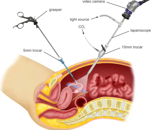
MIS is performed by making small incisions in the body close to the area of interest. An exam-ple of MIS can be seen in figure 2.1. Usually, trocars are placed that help guide the surgical tools towards their target. Because of the limited space available during surgery, visibility is acquired using endoscopes, which are small cameras that can enter the body. These endocopes are usu-ally stiff so that precise manual positioning is possible. The disadvantages of this stiffness is that it is very hard to reach behind organs, making surgery that is not close to the point of entry very difficult.
NOTES is surgery that is performed via the natural holes of the body, so that no incisions are required. Because of this, the tools required have to follow the natural path within the body and therefore have to be flexible. This flexibility assists in reaching the surgical target, but can also lead to positioning difficulties and painful collisions.
[image:11.595.173.434.471.693.2]MIS and NOTES therefore put resctrictions on the tools that can be used. The other way around, there exist tools that enable MIS and NOTES by introducing new ways of reaching or interacting with target organs. A steerable endoscope that can be used for surgical intervention is a tool that enables MIS and NOTES by making it possible to reach targets that lie behind other organs and to avoid obstacles.
2.1.2 Robotic endoscopes in literature
Several robotic endoscopes exist that can not only inspect, but perform surgery as well. Gifari (Gifari, 2018) performed a literature study listing the different designs and their advantages and disadvantages in the context of MIS and NOTES. The review looks at state-of-the-art robotic en-doscopes and lists Invendoscopy (Rösch et al., 2008), Neoguide (Peters et al., 2018), MINIR (Kim et al., 2017), Meshworm (Bernth et al., 2017) and STIFF-FLOP (Cianchetti et al., 2014). While Neoguide meets all requirements set, the final requirement added later, for MR-compatibility, is not met. Having a robotic endoscope that is MR-compatible introduces many options for localization of the endoscope that can assist in surgery.
An MR-compatible endoscope does not include metals and can not use electronic signals within the endoscope itself. Doing so would lead to dangerous situations with the high mag-netic field of the scanner or would result in distortions in the images. By making the endoscope MR-compatible, the images of the MRI can be used to steer the robotic endoscope towards its target. A mix of different sensor techniques is then available to correct for any disturbances. The research in the use of MRI during surgery is also closely related to other research performed at RaM, such as the MURAB project (RaM, 2019b) and MRI-compatible robotics (RaM, 2019a).
[image:12.595.172.399.337.564.2]2.1.3 STIFF-FLOP and MOLLUSC
Figure 2.2:STIFF-FLOP (PIAP, 2019)
An advanced soft robotic endoscope design is the Stiffness Controllable Flexible & Learnable Manipulator for Surgical Operations, or STIFF-FLOP (Cianchetti et al., 2014; Abidi et al., 2018), seen in figure 2.2. This design is potentially MR-compatible as it works by pneumatic actuation and contains no materials that can interfere with the MRI. The modules of STIFF-FLOP contain three pneumatic chambers that elongate and bend the module when air pressure is applied, as can be seen in figure 2.3. Different methods of sheathing (in the different versions of the module) constrain the radial expansion of the manipulator and make sure the air pressure is used for the actuation only. Although it is advanced, the design of STIFF-FLOP has not been used in clinical practice. The reason for this is that the design could still be improved a lot before it is actually suitable for surgery.
simulta-neously would decrease the maximum bending angle of the module. Activating two chambers simultaneously is necessary for using all degrees of freedom (DOF) of the manipulator. Al-though this problem was fixed in a later STIFF-FLOP design, this new design lacked the stiffen-ing mechanisms required for precision and force durstiffen-ing surgery. For this reason Gifari designed a new module based on the first version of STIFF-FLOP containing four pneumatic chambers and granular jamming sacs, integrated in the pneumatic chambers, for stiffening (Gifari, 2018).
Figure 2.3: A STIFF-FLOP module bending due to applied air pressure (without sheathing that con-strains radial expansion) (Cianchetti et al., 2013)
The design of the endoscopic module of Gifari is the starting point of this research towards a multi-module endoscope based on pneumatic actuation.
2.2 Soft continuum actuators
2.2.1 Soft robotics
There is an increasing trend in the use of soft materials in surgical and non-surgical appli-cations. The biggest advantages of using soft materials is that they are safer for interaction, that they enable new actuation methods, and, relevant for this research, that they can be MR-compatible (Rus and Tolley, 2015; Laschi et al., 2016). The downside of soft robots is that they are inherently compliant. While this makes them safer to use, it also means that disturbances have a significant influence on the behaviour of the actuators. This means that the design and control of soft robotics is harder and that modelling is not trivial. Some examples of soft robotics are a soft robotic gripper based on particle jamming (Brown et al., 2010), which shows a new form of actuation, a soft robotic glove for rehabilitation (Polygerinos et al., 2015), which is safer than the alternatives, and of course the MR-compatible soft robotic endoscopes STIFF-FLOP and MOLLUSC.
As modelling of soft robotics is harder than modelling rigid link robotics, methods have been developed that aid in approximating the kinematics of soft robotics by rigid link kinematics, so that conventional and successful techniques can still be used.
2.2.2 Kinematics
The soft robotic endoscope can be seen as a multisegment robot arm. Each segment can be actuated and the end effector position will be determined by the kinematics of the whole. The difference between the soft robotic endoscope and a standard robot arm is that the endoscope has no rigid links, which means that the kinematics are not straightforward. This is a known problem in soft robotics and several control strategies have been designed to overcome this problem (Webster III and Jones, 2010).
elongation of all modules are known, the position of the end effector can be determined as well. This means that three parameters per segment are required for describing the configuration of the robot. A schematic representation of the constant curvature approximation and the three associated parameters is given in figure 2.4.
Figure 2.4:The constant curvature approximation showing how three parameters are required to fully define the shape of a bending soft robotic snake-like module. (a) is a side view showing how the bending angleθand the curvature radius can be used to find the location of the tip of the module. (b) is a 3D view showing that the radius is directly related to the curvatureκof the module and that the bending direction is defined byφ. While the bending directionφis independent of the other variables,κ,land θare all linked. Only two of these three variables are necessary for completely defining the bending shape. In constant curvature kinematicsκ,l andφare used. randθcan be calculated when desired. (Webster III and Jones, 2010)
Jones and Walker (Jones and Walker, 2006) give a method for mapping these three parameters to the standard rigid link kinematics. In this way, the problem of controlling the soft robot can be limited to the hardware. Standard techniques can be used until the pressures for the pneumatic chambers have to be determined using a specific mapping. The characterization of the bending angle dependent on chamber pressures of the endoscope has to be used then. Figure 2.5 shows the different spaces for describing the kinematics and the mappings between them.
Figure 2.5:Mapping between different spaces in constant curvature kinematics (Webster III and Jones, 2010). The actuator space is defined by the behaviour of the actuators and is therefore specific for a certain actuator design. The configuration space is defined by the constant curvature approximation of the robot and contains the values of the three paramters (κ,φ, andl) per module. The task space is independent of the robot that is used and contains the standard kinematics.
3 Design aspects of the endoscopic module
From literature and experiments it followed that the pneumatically actuated bending cylindri-cal module, such as STIFF-FLOP and MOLLUSC, is a very suitable candidate for the steerable robotic endoscope application when MR-compatibility is taken into account as well. The de-signs of STIFF-FLOP, and the improvements of Gifari, therefore form the basis of the soft robotic endoscope. The goal of this chapter is to select a final design that best fits the requirements de-termined by the system level design requirements, based on this type of module. In order to do this, the working principle of the module will be analyzed first.
This chapter begins with the system requirements of the endoscope so that the requirements of the module can be formulated. These requirements will be checked for different types of cylindrical modules by analyzing the working principle behind the actuation of the modules. A study is performed on the influence of sheathing, the number of pneumatic chambers, and the volumetric design of the pneumatic chambers. Finite element simulations and an analytical model will be used for the comparison between the bending angles of the modules based on the amount of pressure applied. While there are advantages and disadvantages to all design aspects, it is clear that a 3-chamber inner sheath module is the best choice for the soft robotic multi-module endoscope in this application where controllability and scalability are critical.
3.1 Requirements
In order to define the requirements of the endoscopic modules, the requirements for the endo-scope (the system requirements) have to be defined first. By making this distinction between module level and system level requirements, the endoscope system level design is not directly dependent on the module design. It is logical that the module requirements follow from the endoscope requirements, but some system level requirements are not dependent on the type of module that is used.
System level requirements
Dimensions MIS and NOTES put strict size limits on the tools that are used. Standard trocar sizes are between 3mm and 10mm (Blinman, 2010), which mean the endoscope diam-eter should stay below this value in order to be usable. In general, for the diamdiam-eter of a robotic endoscope, smaller is better to keep the impact minimal, but a tradeoff can be made when other requirements have to be met. No clear requirements on the dimen-sions of the endoscope will be formulated for this project. Colonoscopes require a length of at least 150cm in order to be able to reach the end of the large intestine, see figure 3.1. The dimensions of the endoscope will follow from the module dimensions and the required dynamics. Because downscaling soft robotic endoscopes is still an open issue, the general requirement is that size constraints should be kept in mind during the de-sign. Scalability has high priority. In order to make the project feasible, however, the endoscope will not actually be made to scale. It will remain a proof of concept.
be-tween bends require varying non-bending sections bebe-tween these modules. The length of the non-bending sections should change depending on the position of the tip of the endoscope. This is why the endoscope has to be made up of a series of modules that can achieve the bending radius of the smallest bend. The number of modules is then the total length divided by the length of a single module. For the proof of concept in this project, at least three modules will have to be put in series. Scalability in terms of the number of modules will be a design guideline. Requirements for the elongation of the modules will not be set.
Figure 3.1:Typical dimensions for the large intestine (Whitmer, 2007)
Stiffness The soft robotic endoscope should both be compliant and stiff, depending on the situation. It should be able to support itself, so that contact with the environment can be minimized. This means that the system should have stiffening capabilities for when force or precision is required. Base stiffness should be high (or low) enough so that the dynamic requirements can be met. Stiffness after stiffening is determined by the sys-tem design and should be high enough to support the dynamics and control. Because a lot of research has already been performed in the direction of stiffening of soft robotics, and a lot of design options are possible, the endoscope in this project will not contain a stiffening mechanism. A small study was performed on different stiffening mechanisms in literature and the most suitable method seems to be layer jamming (Kim et al., 2012). Layer jamming has the benefit that its design can be viewed separate from the endoscope itself, because the mechanism can be placed outside of the modules. The literature study is not included in this work, but a small summary can be read in appendix A.
Safety Expected safety problems arise around the maximum usable pressure for realizing the bending of the modules and the materials that will be used for the construction. The device should be designed with safety of the patient and operator in mind, but since the endoscope will introduce some new concepts, the safety for the patient will be an aspect left open for improvement. No maximum value for the used pressure will be set.
this study and that feedback on the position and configuration of the whole endoscope is available. Position guarantee in feedforward is therefore not a requirement. Feedforward control, by manual input for example, should be implemented.
Other All parts of the endoscope that have to be close to the patient will be made MRI-compatible. Ferreous materials will be prohibited, as will all other metals, because they pose a large risk towards the safety of the patient and the operator. Electronic signals will not be used close to the patient, as they will interfere as well.
Because this work is based on previous work performed by Gifari and the research focus is on the multi-module endoscope, some requirements for the endoscopic module can already be formulated by looking at MOLLUSC.
Module level requirements
Dimensions With previous work focussing on the design of a single endoscopic module, the di-mensions of the individual modules will be adopted from MOLLUSC in the multi-module design. The module will therefore be 45mm in length and have an outer diameter of 25mm, with a central cylinder with a diameter of 8mm in order to guide surgical instru-ments. These dimensions are not suitable for use in clinical practice and the device re-mains a proof of concept.
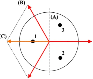
[image:18.595.187.367.521.674.2]Dynamics Seen from the top, a module should be able to move in all directions in the plane (the bending direction). Pneumatic chambers can only elongate and not contract, which means that only an antagonistic pair of chambers can cause actuation in both directions along a single axis. For actuation in a plane (2D) this means that at least three pneumatic chambers are required. The reason that the minimum is not four is because two cham-bers spaced at 120◦ can substitute one of the chambers of the antagonistic pair. This principle is shown in figure 3.2. The minimum required bending angle of the module seen from the side follows from the path planning and is 40◦with the specified dimen-sions of the module. This was determined from simulations by another student at RaM (J.W. Lageveen) and might change with the module dimensions or path planning algo-rithms in the future.
Figure 3.2:Vectors indicating the bending moment during actuation of a 3-chamber module; anatago-nistic actuation is possible by three chambers that are spaced 120◦apart due to the sum of vectors. The
While the modules of the type of STIFF-FLOP and MOLLUSC meet the basic requirements, choosing the right design requires insight in the behaviour of the module under actuation. Based on the results of Cianchetti et al, Fra´s et al., and Gifari (Cianchetti et al., 2014; Fra´s et al., 2015; Gifari, 2018), it is expected that this behaviour differs significantly with each design. So, while a limited set of options is left, the requirements are not clear enough to pick the final design. This is why the bending behaviour of the module will be treated next.
3.2 Study on the theory of bending
The modules bend because pneumatic chambers are pressurized, so that a force is applied that results in elongation and bending of the module. This force is directly proportional to the area of the pneumatic chambers, which means that a higher force is applied when the pneumatic chambers expand radially (bulge as was shown in figure 2.3). This bulging was observed in modules without sheathing and in the modules with outer sheath. The outer sheath of MOL-LUSC prevents extreme bulging for example, but the chambers can still expand inwards. This was found by both Fra´s et al. (Fra´s et al., 2015) and Gifari (Gifari, 2018). In the second and third version of STIFF-FLOP less bending is observed for the same amount of pressure because the chambers do not expand significantly (Fra´s et al., 2015).
The number of chambers has a large influence on the bending behaviour of the module as well. One of the improvements of MOLLUSC in comparison to the first version of STIFF-FLOP is based on the number of chambers. This is why a study based on analytical calculations and Finite Element (FE) simulations was performed to gain insight in the design aspects that deter-mine the amount of bending of a module.
Several comparative studies have already been performed on the influence of design choices on the pneumatic chambers of STIFF-FLOP modules and similar soft robotic endoscope mod-ules. Performance of soft actuator modules has been assessed based on the bending angle determined by chamber pressure and volume. Elsayed et al. (Elsayed et al., 2014) compare different pneumatic chamber shapes and their influence on the bending behaviour of the ma-nipulator. Fra´s et al. (Fra´s et al., 2015) show the differences between two methods of constrain-ing the radial expansion of the endoscope, which reduces the risk of failure of the chambers. The improvement in bending with two pneumatic chambers actuated in a 4-chamber design compared to the 3-chamber design is shown by Gifari and Naghibi et al. (Gifari, 2018; Naghibi et al., 2019). Although informative, these studies each focus on a single issue, even though their design choices cannot be viewed separately.
The impact of the size of the pneumatic chambers was already explained. Dimensional re-quirements in multi-module endoscope design demand that limited space is shared between pneumatic chambers and components required for fixing multiple modules in series and other functionalities. These components include pneumatic pressure tubes, connector segments, the central cylinder for surgical instruments and stiffening mechanisms. The dimensions of the pneumatic chambers cannot be decreased without increasing the required pressure for ac-tuation. High pressure is not desired, as this poses a risk to patient safety (Cianchetti et al., 2013). A way to overcome this problem is by looking at the volumetric design (lengthwise ge-ometry) of the chambers as well.
The study therefore assesses the influence of the following design aspects of the pneumatic soft module, on the function of the endoscopic module:
1. The methods of constraining radial expansion, or sheathing type
2. The number of chambers
By looking at soft robotic endoscope modules and modelling their behaviour dependent on pneumatic chamber design, this study will provide insights and results that can be used in the system design of a soft, steerable, flexible endoscope, so that the design for the endoscopic module can be finalized.
3.2.1 Evaluation of design aspects of the pneumatic chambers
The analytical static model for position estimation of a soft robotic endoscope module is de-scribed by Fra´s et al. (Fra´s et al., 2014). Using this model, it is possible to predict the general behavior of the modules under various design choices. The amount of elongation of a cham-ber depends on the stiffness of the module (which is depended on geometry) and the amount of force that is applied in the direction of elongation. The force acting on any cross section of the chamber is proportional to the area and the air pressure (Fra´s et al., 2014), which is also why the bulging effect introduces a strong non-linear effect in the pressure versus the bending angle curve. The bulging increases the cross-sectional area of the chamber. This also explains why higher pressures are necessary once the radial expansion of the chambers is constrained. The cross-sectional area of the chamber does not increase, so the bending moment does not increase. Both the non-linear effect due to bulging and the higher required pressure due to radial constraints are demonstrated by Fra´s et al. (Fra´s et al., 2015).
1) Radial expansion constraint (sheathing) Bulging in the soft pneumatic actuator increases the module diameter and is undesired (Cianchetti et al., 2013). Different methods are being used to constrain the radial expansion of the pneumatic chambers. The designs from Gifari and De Falco et al. (Gifari, 2018; De Falco et al., 2017) use a crimped sheath that surrounds the whole module, keeping its diameter within bounds. While effective in preventing extreme bulging outside of the module, the sheath’s irregularities combined with the soft material of the manipulator introduce non-linearities that affect the mod-ule’s performance, especially when actuating two chambers simultaneously, as is shown by Cianchetti et al. and De Falco et al. (Cianchetti et al., 2014; De Falco et al., 2017). With only the outer sheath limiting the radial expansion of the 3-chamber module, the bend-ing angle with two chambers actuated simultaneously is shown to be much less than the bending angle of the module when only a single chamber is actuated. This is caused by chamber deformation when pressure is applied, leading to a shift of geometrical centers (Fra´s et al., 2015). The deformation introduces a dependency on the actuation order as well (Fra´s et al., 2015; Gifari, 2018). Two solutions have been proposed to counteract this effect, namely moving the sheath to the inside of the chambers and changing the number of pneumatic chambers.
Figure 3.3: Outer sheath modules show shifting of the centers of the actuation chambers when the chambers increase in diameter at higher pressures, this decreases the resulting moment arm when two chambers are actuated simultaneously (Gifari, 2018).
3) Volumetric design of the pneumatic chambers With the knowledge that the area of the cross section of a chamber determines the force with which the stiffness of the chamber walls is overcome, it might be beneficial to look further than just the shape of the cross sec-tion of the chambers. This cross secsec-tion does not necessarily have to be constant over the length of the chamber. While studies have been performed on different shapes of the cross section of the chambers and many different designs of the manipulator were cre-ated (Gifari, 2018; Gerboni et al., 2015; Suzumori et al., 1991; Holdar and Engeberg, 2018; Cianchetti et al., 2013), all these studies assumed an equal shape all the way through the length of the chamber. This study will also look into the effects of varying the size or shape of the chamber over the length of the chamber. By being able to shape the whole chamber, instead of only the cross sectional area, there is more freedom to change the space available for other functionalities.
Chamber designs varying their cross section benefit from the method of constraining the radial expansion of the pneumatic chambers, because without this constraint, the chambers would expand into the area that is necessary for other functionalities. With the radial expansion constrained, the volume of the pneumatic chambers can be shaped around the space required for including other functions, such as stiffening methods, as applied in STIFF-FLOP, or routing the pressure tubes or connecting the modules in series, without having to lower the volume of the chamber too much. Although a lower chamber volume decreases the time it takes for a certain pressure to build up, which increases the possible control bandwidth, the volume of the chamber cannot be changed without affecting the pressure required for bending. This is because the bending angle of the whole module is the result of integrating the bending angle of every infinitesimal slice of the module (Fra´s et al., 2014).
Figure 3.4: The three 3-chamber soft robotic endoscope modules (including empty central cylinder) with different volumetric chamber designs: (A) The basic cylinder design, (B) The concave design, and (C) The sharp edged design.
In theory and regarding the multi-module design and fabrication, the available methods all have their advantages and disadvantages. As a result, comparing different modules using finite element simulations can give a better understanding on the implications of different choices, as described before, on the improvement of the module functionality. The methods for com-paring the design aspects will be described next.
3.3 Methods for analyzing the design aspects
3.3.1 Finite Element simulations
A generic finite element model of a soft endoscopic module (figure 3.5) was developed in Abaqus v2018 (Simulia, Providence, RI, USA). A dynamic implicit solver was used with quasi-static simulation. The module was meshed with second-order tetrahedral elements (C3D10) with an average element size of 2mm. Similar to the physical model utilized for validation, the module had a diameter of 25mm and a length of 45mm, with a central cylinder of 8mm in diameter. The total length of the chambers was 30mm, and in all cases, the chambers were configured circumferentially symmetrical around the central cylinder at a radius of 8.25mm. Different geometrical design aspects were modelled to assess the variations in number of chambers (three versus four chambers) and chamber volumetric profiles. Moreover, in order to evaluate different types of radial expansion constraints or sheathing types, fiberic sheath was applied around either the module body, chamber, or both, using the Holzapfel-Gesser-Ogden hyper-elastic material model. In each case, a linearly ramped pressure from 0 bar to 1 bar was applied to the chambers. The bending of the module tip was extracted at increments of 0.05 bar of input pressure. Finite element simulations have been set up by, and were performed by, H. Naghibi.
3.3.2 Validation of the finite element simulations
Figure 3.5:The finite element model (cut view) of the 4-chamber module with three different sheathings modelled here as: body (outer) sheath (A), chamber (inner) sheath (B), and both outer and inner sheath (C).
• The simulation of the 4-chamber design with outer sheath for one and two chamber ac-tuations will be compared to the results of the study of Gifari and Naghibi et al. (Gifari, 2018; Naghibi et al., 2019).
• The simulation of the 3-chamber design with outer sheath for one and two chamber ac-tuations will be compared to the results of the old STIFF-FLOP design (Fra´s et al., 2015).
• The simulation of the 3-chamber design with inner sheath for one and two chamber ac-tuations will be compared to the results of the new STIFF-FLOP design (Fra´s et al., 2015).
3.3.3 Comparing design aspects
1) Radial expansion constraints (sheathing) To investigate the influence of different types of sheathings to constrain the radial expansion, the 4-chamber module was modelled with no sheath, with a sheath around the chamber (inner sheath), with a sheath around the body (outer sheath), and with a sheath around both the chamber and the body (both sheaths).
2) Number of chambers In order to compare the effect of the number of pneumatic chambers, a comparison was made between the 3-chamber and 4-chamber designs with either the inner sheath, or the outer sheath only. In any of the assessed cases, one chamber ac-tivation and two chambers acac-tivation were simulated. The cross sectional profile was selected to be a half circle with a radius of 4mm.
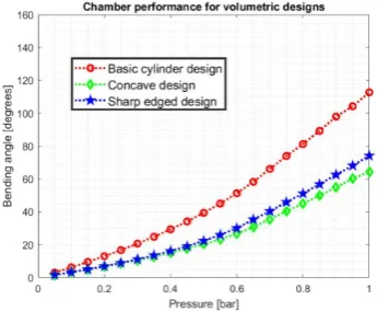
3) Volumetric design of pneumatic chambers The influence of the volumetric chamber design was investigated by comparing three different designs of the 3-chamber module. As il-lustrated in figure 3.4, the basic cylinder design (A), an hourglass-shaped concave design (B), and an I-shaped sharp-edged design (C), were modelled and simulated. The cham-ber cross-sectional profiles were circular in all cases, with a diameter of 6mm which was reduced to 3mm in the concave and extreme sharped edged cases. This was combined with an inner sheath to ensure that this cross section would deform minimally.
3.4 Results
the general trend of the curves is similar, the simulated bending angles of the modules require 0.1 bar less pressure. This offset is mainly expected to be due to a gap between the outer surface of the module and the sheath. The simulation results, therefore, were shifted by 0.1 bar as shown in figure 3.6a. The results of the simulations for the 3-chamber design are shown in figure 3.6b. Experimental results of the 3-chamber STIFF-FLOP module were found by Fra´s et al. (Fra´s et al., 2015). Despite the slight differences in bending values, the overall trend is similar. The differences in bending can be due to the use of a different chamber cross sectional profile by Fra´s et al. This was circular, whereas a half-circular profile was modelled in the finite element simulations.
(a)The simulated and experimentally measured per-formance of one and two chamber actuation in the 4-chamber module
(b)The simulated performance of one and two cham-bers actuation in the 3-chamber module
Figure 3.6:Results for validating the finite element simulations
2) Radial expansion constraint (sheathing) All results from the simulations of a 4-chamber module with a single chamber actuated are shown in figure 3.7a. Designs with an outer sheath achieve more bending for the same pressure. The bending of the design without a sheath drops off very quickly, which is not according to experimental results (Elsayed et al., 2014). With no sheath, the simulation could not go beyond 0.35 bar of pressure due to highly deformed elements leading to numerical instability, as a result of excessive radial expansion.
(a)The performance of the 4-chamber module with dif-ferent sheathings
(b) The comparison between 3-chamber and 4-chamber modules, with different types of sheathing
3) Number of chambers The performance curves for 3-chamber and 4-chamber modules with chamber (inner) and body (outer) sheaths were compared in figure 3.7b. The two cham-ber actuation results are also shown.
[image:25.595.209.382.200.342.2]4) Volumetric design of pneumatic chambers The simulation results of the three volumetric designs are shown in figure 3.8. The basic design achieves more bending for the same amount of pressure. At 1 bar of pressure, the bending angles of the concave and sharp-edged designs are about half the bending angle of the basic design.
Figure 3.8:The comparison between the three different volumetric chamber designs
3.5 Discussion
In this study different design aspects in a soft endoscopic module were assessed. For this pur-pose, a finite element model of the endoscopic module was developed and validated against experimental measurements. Subsequently, different types of radial expansion constraints (sheathing), number of chambers, and volumetric designs of the pneumatic chambers were compared. As expected, the chambers expand inwards when only an outer sheath is used and the required pressure for the same bending is lower than when the inner sheath is used. The effect of shifting geometrical centers when only an outer sheath is used is clearly visible. The 3-chamber design with a single actuated chamber outperforms the dual chamber actuation. The performances of single and dual chamber actuation are similar in the 4-chamber design, showing that using four chambers can negate the effect of the shifting of geometrical centers. Using both the inner sheath and the outer sheath does not result in an improvement in bending performance compared to only using the inner sheath. Using both sheaths would therefore not be beneficial, as its fabrication would be the most complex of all the designs. Using four chambers instead of three results in more bending, regardless of the type of sheath. Because all designs have the same chamber cross section diameter, the 4-chamber module cross section area has less material. It is therefore expected that this result is mostly due to the lower stiffness of the 4-chamber modules. The results of the inner sheath show that the 3-chamber design has similar bending for both the single and the dual actuated case. For the 4-chamber design, the bending for the dual actuated case is significantly higher than for the single actuated case. This was expected, due to the higher resulting moment.
though the 4-chamber design requires less pressure for the same amount of bending, as the area per chamber can be increased more than when four chambers are used in the same size of module. This lowers the required pressure again, although more research is necessary to confirm whether similar performance can be achieved. Other advantages of using three pneu-matic chambers instead of four is that more space is available for routing pneupneu-matic tubing and that it is more suitable for downscaling the module. An example of a 3-chamber design with larger chamber cross section area compared to module cross section area is the last version of STIFF-FLOP, which has two parallel tubes per actuation chamber (Abidi et al., 2018). Because scalability is an important requirement of the soft robotic endoscope, this project will continue with the 3-chamber inner sheath design. Experiments on the achievable performance differ-ences between the 3-chamber and 4-chamber inner sheath designs are recommended, but will not be performed in this project.
As inferred from the results of this study, the basic design outperforms the concave and sharp-edged designs in terms of pressure per degree of bending angle. Although theoretically hypoth-esized, experiments to confirm this would be beneficial. Since the non-basic designs require less volume, the requirements for the final endoscope determine which design parameters are more critical. If more space is required, but pressure is not an issue, chamber volumes can be made smaller without changing the basic geometry. If more space is required while the pres-sure has to be kept low, the volumetric design can be made to just fit the available space. This gives the maximum bending versus pressure curve within the volumetric limitations. It is ex-pected that the concave and sharp-edged designs perform better than a basic design with a diameter equal to the smallest cross section of these non-basic designs. This study focused on chambers with equal maximum cross section areas. The volumes of the chamber designs were therefore unequal. More research is required to compare chambers with equal volume. The optimal shape can then be determined by the application requirements.
3.6 Conclusion
With the desire to find the most suitable soft endoscopic module, the combination of the meth-ods of constraining radial expansion and the number of chambers was considered, as well as the influence of different volumetric designs. Results were obtained using finite element sim-ulations that were validated with experiments performed in the lab and in other comparative studies.
Within the designs compared, the 3-chamber inner sheath design is the most optimal for control and pneumatic hardware requirements. The 4-chamber outer sheath design should be used if minimizing actuation pressure has the highest priority. The basic volumetric de-sign should be used, unless other multi-module endoscope components require a trade-off in which a decreased bending performance is permitted. Further research is required to deter-mine whether the performance of a 3-chamber inner sheath design with larger chamber cross sectional area can match the performance of a 4-chamber inner sheath design. A study on whether nonbasic volumetric designs can outperform basic designs with comparable volume should be performed as well.
4 Module design and fabrication
The module design of the endoscope was chosen to have three pneumatic chambers with inner sheaths. The goal of this chapter is to finalize the design of the module based on the chosen design aspects and verify that the endoscopic module is suitable for the application. The multi-module endoscope requires that multiple multi-modules are fabricated and that their behaviour is known and predictable so that feedforward control can be implemented.
The first part of this chapter contains the design of the module based on the study in the pre-vious chapter. Part of the module design is the fabrication technique required for realizing the design. While some of the steps in the fabrication process could be used directly from the work of Gifari, some changes had to be made in order to include the inner sheaths. The molds were upgraded for easier fabrication as well, giving more consistent results, which in turn makes the modules suitable for physical modelling. A physical model will therefore be constructed that gives the relation between input pressures in the chambers and the resulting bending angles of the module.
This three-dimensional linear model is based on the work of Fra´s et al. (Fra´s et al., 2014). The working of the modules and the accuracy of the physical model will be verified by characteriz-ing the bendcharacteriz-ing angle and direction of the modules dependent on the input pressures. It was found that the physical model is not accurate in predicting the bending angle when a single chamber is actuated and that it showns a large error when two chambers are actuated simul-taneously. The model is therefore expanded to better describe the behaviour of the modules. Using this model, it becomes possible to describe the behaviour of a module by determining a single parameter per chamber instead of characterizing the whole actuator range, as was done by Gifari and Jansen (Gifari, 2018; Jansen, 2018). This makes control easier to implement and lessens the impact of the fabrication differences in the pneumatic actuators.
The fabricated modules will be tested and the bending angle dependent on the input pressures will be characterized. The results are used to verify the physical model and check the design requirements.
4.1 Design
4.1.1 Dimensions
In order to focus on the multi-module endoscope design, the module design is kept close to the design of MOLLUSC, while the necessary changes based on the chosen design aspects will still be implemented. By keeping dimensions similar, a better comparison between different modules is possible as well. This means that the outer dimensions and the materials used will not be changed. The design and dimensions of the modified module are shown in figure 4.1. Dimensions of the new module will be kept as close to the original values as possible. The main differences between the modules are the number of chambers and the method of constraining the radial expansion of the chambers. The inner thread design requires the chambers to be circular, because any non-circular chamber shape would first deform to a circle so that forces along the circumference of the chamber are equalized. The deformation of non-circular shapes would introduce unpredictable behaviour, and might lead to shifting of the geometrical centres of the chambers, which is undesired. This means that the chamber molds have changed as well.
4.1.2 Fabrication
Figure 4.1:The design of the new module with inner sheath
of the module. Both materials consist of two components that have to be mixed and poured into a mold to form the module. The molds have been 3D-printed using an Object260 Connex3 using the VeroWhite and VeroClear materials (StrataSys, Ltd), which gives a smooth structure to aid in releasing the module from the mold after curing. A release agent is still used as well.
Figure 4.2: The endoscopic module with inner sheath, with (A) the top part made of Dragon Skin 10 Fast, (B) the main part made of Ecoflex 00-50, and (C) a chamber with internal thread (sheathing) that prevents radial expansion of the pneumatic chambers.
[image:28.595.223.344.365.555.2](a)The mold for creating a 0.5mm thick layer of Ecoflex around the pneumatic chambers (open)
(b)The mold for creating a 0.5mm thick layer of Ecoflex around the pneumatic chambers (closed)
(c) The mold for creating the en-doscopic modules with inner thread (open)
Figure 4.3:The molds for creating the endoscopic modules
00-50 is then poured to finish the main part of the module. After the required curing time, the main part of the module is taken from the mold and the chamber molds are carefully removed. The module is rotated in the third step and new chamber molds, that are easier to remove via the smaller holes, are placed via the other side of the module. The main mold is reconfigured for the final length of the module and the mixing and pouring steps are repeated with Dragon Skin 10 Fast. When this material is cured as well, the basic endoscopic module is finished and the molds can be completely removed. Each new module is tested with air pressure up to 1 bar to check for leaks or deformations that could lead to rupture of the material.
4.2 Physical model
Fra´s et al. (Fra´s et al., 2014) describe a physical model for determining the bending angles of the STIFF-FLOP module for both the unloaded and the loaded cases based on the constant curvature assumption. The model takes the force on every cross section of the module, that is dependent on the applied pressure times the chamber crossectional area, and calculates the moment and force that bend and elongate the module. By summing all infinitessimal angles over the whole length and elongation of the module, the final bending angle is obtained. Be-cause the moments are vectors, it is also possible to calculate the bending direction, although this is not directly demonstrated. That the model can be used for determining the three dimen-sional configuration, is demonstrated however. The relation between the theoretical model and experimental data is not shown.
∆l= Z l0
0 ∆
d l= Z l0
0
Fp
AEd l (4.1)
d l: length of a slice of the module,Fp: the force due to the pressure times the chamber cross sectional area, A: the area of the cross section of the module that is not part of the chambers (so the module’s material) (Fra´s et al., 2014).
κ= 1
ρ= M
E I (4.2)
κ: the curvature at a slice of the module,ρ: curvature radius,M: moment due to the chamber pressure times chamber cross sectional area times the moment arm,I: the second moment of area of the slice of the module (Fra´s et al., 2014).
α= Z l0+∆l
0
1
ρd l (4.3)
α: the total bending angle of the module,l0: the initial length of the module,∆l: the extra length of
the module due to the total actuation force,d l: the length of an infinitessimal slice of the module (Fra´s et al., 2014).
4.2.1 Implementation
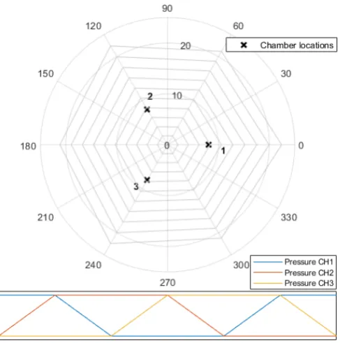
This physical model is implemented in Matlab (MathWorks) and used to predict the bending angle and direction of the endoscopic module. Appendix B shows the steps required for calcu-lating the bending angle and direction from the pressures applied to the three chambers. Using the Young’s modules of Ecoflex 00-50 equal to its 100% modulus of 12psi, or 82737.1 Pascal, (Smooth-On, Inc) the bending angles and directions are plotted for different maximum pres-sures from 0.1 bar to 1 bar by varying the chamber prespres-sures linearly. The chamber prespres-sures were chosen in such a way that the bending direction of the module would trace 360◦. This was done by always having at least 1 chamber at maximum pressure, while varying one of the other chambers. The resulting actuator space is shown in figure 4.4.
As can be seen, a hexagonal figure is traced by always setting one of the chambers at maximum pressure. The six corners are the points of single or dual chamber actuation at maximum pres-sure. It is clear that the amplitude (which is the bending angle) of these points is not equal. Dual chamber actuation gives a slightly larger bending angle compared to single chamber actuation. This was found by the study in chapter 3 as well.
The reason for this larger angle is directly clear from the model. By actuating two chambers simultaneously, the amplitude of the moment arm is equal to the case with single chamber actuation, but the elongation of the module is larger. The model assumes constant curvature, which means that the curvature of the module is the same over the whole length of the module. The model determines this curvature using the moment arm and integrates this bending de-pending on the moment arm over the total length of the module. This determines the angle of the end face of the module, or the bending angle. A longer module has a higher bending angle with the same moment arm.
Although a model can be used to predict the bending of the module under defined chamber pressures, it is necessary to verify this model and to compensate and alter the model for any deviations that might occur in an actual endoscopic module. This is why the pressure versus bending angle curve of the fabricated modules will be characterized.
4.3 Characterization
Figure 4.4:Bending angle and direction based on the applied chambers pressures, based on the physical model. The main plot axes contain circles of equal amount of bending, while the bending direction is shown in 2D. The locations of the pneumatic chambers are shown (not to scale). The pattern of applied pressures is shown in the subplot. Each pattern is scaled with a maximum amount of pressure (ranging from 0.1 bar to 1 bar) and every closed hexagonal shape is linked to one of these maximum pressure values.
4.3.1 Method
Characterization of the modules is performed using a setup consisting of pressure regulators from Festo and an Aurora Electromagnetic (EM) tracker (NDI Medical). The EM tracker is used to measure the bending angle of the module and outputs the six DOF position and orientation of the sensor that is placed on the tip of the module. The rotation output of the tracker with a 6 DOF sensor is in quaternions with an accuracy of 0.55◦(NDI, 2019). Matlab is used to transform the quaternions to rotation matrices.
Figure 4.5:Schematic representation of the values that are measured using the EM tracker and that are used in calculating the bending angle of the module for the applied pressures. (A) is the module, (B) is the axis of rotation that is perpendicular to the field of view, and (C) is the rotation angle represented by the angle of the complex eigenvalues of the rotation matrix.
Next to the characterization of the amount of bending, the bending direction for the combina-tion of two chambers with different input pressures will be measured as well. This will be done using two pressure regulators and varying the pressures in both chambers from 0 bar to 1 bar in steps of 0.25 bar. The bending direction is a vector perpendicular to the bending axis that is found, projected onto the table on which the module stands. For processing the data, all bend-ing directions are defined relative to the bendbend-ing direction of the module when only one of the chambers is actuated with 1 bar of pressure. Three sets of measurements will be performed, one for every pair of chambers.
4.3.2 Results
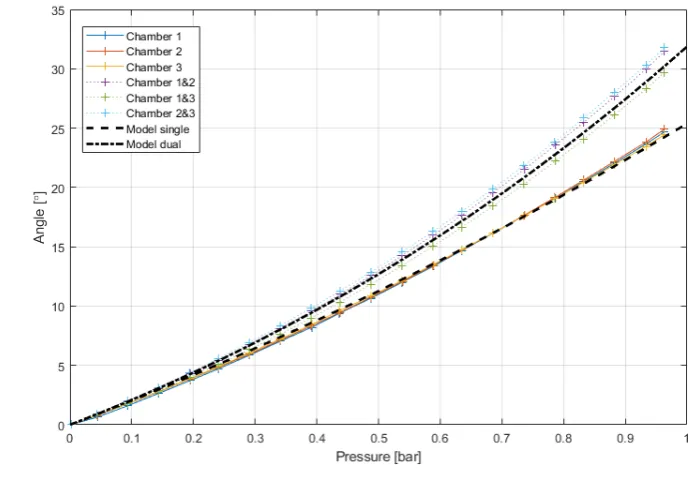
The results of three endoscopic modules are shown in figure 4.6 together with the predictions of the physical model.
It can be seen that bending of the modules is close to linear, but that the lines curve upwards. By combining the graphs in a single figure, it is directly clear that repeatability between modules is achieved. The maximum difference between chambers of different modules is 10% for single chamber actuation and 13% for dual chamber actuation. The differences between chambers within the same module lie within 4% and 8%, for single chamber and dual chamber actuation respectively.
Dual chamber actuation gives higher bending angles than single chamber actuation, as was expected. The single chamber maximum bending angle at 1 bar is close to 25◦. It is also clear that the physical model cannot be used to represent the modules, as the model has an error of at least 4◦at 1 bar of input pressure, with a maximum error of 11◦in case of dual chamber actuation.
Figure 4.6: Bending angle dependent on chamber pressures for the modules 3G, 3H and 3I for sin-gle chamber (CHi) and dual chamber actuation (CHi&j). The calculated bending ansin-gle using the static model from literature is shown as well.
[image:33.595.190.450.433.657.2]4.4 Improving the physical model
The bending angle versus input pressure characterization of several modules shows that the model works well for lower pressures, but does not describe the behaviour well for input pres-sures above 0.5 bar. The reason that the bending angle curve increases more with dual cham-ber actuation, is that the elongation of the module increases this angle as well. The bending angle of the module is the curvature summed over the module’s length. Dual chamber actua-tion elongates the module more than single chamber actuaactua-tion and this adds to the resulting bending angle.
The increase in length due to elongation does not seem to be enough to explain the difference in bending angles between the model and reality. While the bending is dependent on geometry and the Young’s modulus of Ecoflex 00-50, only changing the Young’s modulus to fit the model to the data does not give the desired results. Modelling a material that is less stiff results in higher bending angles overall, but to achieve the measured angles for dual chamber actuation, the predicted angles for single chamber actuation become too high.
It is therefore expected that the modelling error does not lie in the material properties, but in the geometry of the module. When the module elongates, a decrease in diameter can be observed. This decrease in diameter will decrease the second moment of area of the module, which influences the module curvature. For a uniform deformation, the relation between elon-gation and decrease in diameter can be captured in a material’s Poisson ratio. Finding this ratio for Ecoflex 00-50, combined with the fact that the module’s second moment of area scales with
r4, should make it possible to improve the physical model.
This does not hold for the endoscopic modules, however, because their outer diameter is fixed at the connector pieces. This means that the change in diameter of the module is not uniform over its length and that a Poisson ratio cannot be used. In order to improve the model, sev-eral scaling factors for the second moment of area were therefore tried until the predicted and measured bending angles matched at 1 bar of input pressure.
It was found that the second moment of area should be scaled by ( l0
l0+∆l)
3, or the inverse of
the elongation cubed, to give the correct results. This change in the second moment of area based on the elongation of the module is therefore added to the model. The results of the characterization combined with the results of the improved model can be seen in figure 4.8 and 4.9. The model is now able to predict the bending within an error of 2◦, which is under 8%, over the whole actuator range. The improved model of the actuation range based on constant maximum pressure, as was plotted in figure 4.4, can be seen in figure 4.10.
4.5 Discussion
4.5.1 The endoscopic module
Figure 4.8:Bending angle dependent on chamber pressures for the module 3G for single chamber (CHi) and dual chamber (CHi&j) actuation, together with the improved physical model.
[image:35.595.191.451.437.663.2]Figure 4.10: Bending angle and direction based on the applied chamber pressures, with the updated physical model. The main plot axes contain circles of equal amount of bending, while the bending direction is shown in 2D. The locations of the pneumatic chambers are shown (not to scale). The pattern of applied pressures is shown in the subplot. Each pattern is scaled with a maximum amount of pressure (ranging from 0.1 bar to 1 bar) and every closed hexagonal shape is linked to one of these maximum pressure values.
simulations are much faster than fabrication, this will aid in faster prototyping of new modules with different dimensions.
The maximum bending angle of the realized modules is expected to improve by using larger pneumatic chambers, material that is less stiff, and by allowing higher maximum pressures. Not all of this can be directly implemented because of fabrication limitations. More research is required towards modules with higher bending angles.
4.5.2 The physical model
The improved model can be used to predict the bending of a module with inner sheath under known chamber pressures, but it also contains implicit assumptions about the different as-pects of the module. The static model assumes constant chamber cross sectional area, which means it cannot be used to predict the bending of the outer sheath modules. Modelling the modules with outer sheath would require compensation for the force on the chamber crossec-tional area based on the applied pressure. Because the radial expansion is still constrained by the outer sheath, which introduces non-linearities, as discussed by Gifari and Fra´s et al. (Gifari, 2018; Fra´s et al., 2015), more knowledge about the orientation of the module and the size of the other pneumatic chambers is required for this compensation. This means that the inner sheath module requires a simpler model than the outer sheath module.