warwick.ac.uk/lib-publications
Original citation:
Sun, Hao, Luo, Xing and Wang, Jihong. (2015) Feasibility study of a hybrid wind turbine
system – integration with compressed air energy storage. Applied Energy, Volume 137 . pp.
617-628.
Permanent WRAP URL:
http://wrap.warwick.ac.uk/67249
Copyright and reuse:
The Warwick Research Archive Portal (WRAP) makes this work of researchers of the
University of Warwick available open access under the following conditions.
This article is made available under the Creative Commons Attribution 3.0 (CC BY 3.0) license
and may be reused according to the conditions of the license. For more details see:
http://creativecommons.org/licenses/by/3.0/
A note on versions:
The version presented in WRAP is the published version, or, version of record, and may be
cited as it appears here.
Feasibility study of a hybrid wind turbine system – Integration
with compressed air energy storage
Hao Sun
a,b,1, Xing Luo
a,1, Jihong Wang
a,⇑ aSchool of Engineering, University of Warwick, Coventry CV4 7AL, UK b
School of Electronic, Electrical and Computer Engineering, University of Birmingham, Birmingham B15 2TT, UK
h i g h l i g h t s
A new hybrid wind turbine system is proposed and feasibility study if conducted.
A complete mathematical model is developed and implemented in a software environment. Multi-mode control strategy is investigated to ensure the system work smoothly and efficiently. A prototype for implementing the proposed mechanism is built and tested as proof of the concept. The proposed system is proved to be technically feasible with energy efficiency around 50%.
a r t i c l e
i n f o
Article history:
Received 14 March 2014
Received in revised form 7 June 2014 Accepted 30 June 2014
Available online 1 August 2014
Keywords:
Wind turbine
Compressed air energy storage Hybrid system
Mathematical modelling Control strategy
a b s t r a c t
Wind has been recognized as one of major realistic clean energy sources for power generation to meet the continuously increased energy demand and to achieve the carbon emission reduction targets. However, the utilisation of wind energy encounters an inevitable challenge resulting from the nature of wind intermittency. To address this, the paper presents the recent research work at Warwick on the feasibility study of a new hybrid system by integrating a wind turbine with compressed air energy storage. A mechanical transmission mechanism is designed and implemented for power integration within the hybrid system. A scroll expander is adopted to serve as an ‘‘air-machinery energy converter’’, which can transmit additional driving power generalized from the stored compressed air to the turbine shaft for smoothing the wind power fluctuation. A mathematical model for the complete hybrid process is developed and the control strategy is investigated for corresponding cooperative operations. A prototype test rig for implementing the proposed mechanism is built for proof of the concept. From the simulated and experimental studies, the energy conversion efficiency analysis is conducted while the system experiences different operation conditions and modes. It is proved that the proposed hybrid wind turbine system is feasible technically.
Ó2014 Elsevier Ltd. All rights reserved.
1. Introduction
In recent years, wind power generation has shown a robust growth trend worldwide. The global cumulatively installed gener-ation capacity of wind power reached 318,137 MW at the end of 2013, which has increased by more than 163% compared to 120,624 MW in 2008[1]. Such rapid development is mainly driven by the continuous increase in electricity demand and the need for reducing greenhouse gas emissions. However, the nature of fluctu-ation and intermittence of wind makes it very difficult to deliver
power output from wind energy with an instant match to the elec-tricity demand. This nature also brings the negative impact onto the wind turbine system operation efficiency, life expectance and mechanical structures[2]. Thus, new technologies and approaches have been actively researched to alleviate the problems caused by wind fluctuation and intermittence, such as wind turbine pitch angle control, power electronics development for wind power and flexible back-up power generation[3–5]. One of the promising solutions is to introduce an element of stored energy as an alterna-tive energy supply for use when the ambient wind power is insuf-ficient. Various Energy Storage (ES) technologies can provide the service of compensators to work with different types of wind power generation systems, for example, hydroelectric pumped storage, Compressed Air Energy Storage (CAES), flow batteries
http://dx.doi.org/10.1016/j.apenergy.2014.06.083
0306-2619/Ó2014 Elsevier Ltd. All rights reserved.
⇑ Corresponding author. Tel.: +44 247 6523780.
E-mail address:[email protected](J. Wang).
1 The two authors have made equal contributions to this paper.
Contents lists available atScienceDirect
Applied Energy
and flywheels[6,7]. Among the available ES technologies, CAES can be considered as one of the relatively mature and affordable options[6,8,10].
CAES technology refers to storing energy in the form of high pressure compressed air during the periods of low electrical energy demand and then releasing the stored energy during the high demand periods. CAES facilities exist in multiple scales, with long storage duration, moderate response time and good part-load performance [6,7,9]. So far, there are a few successful industrial implementations of large-scale CAES plants serving wind power generation. For instance, after the world first commercialized Huntorf CAES plant started operation, its man-date was upman-dated to include the buffering against the intermit-tence of wind energy production in Northern Germany [9]. Also, the developing advanced adiabatic CAES demonstration project – ADELE by RWE Power and others aims to store large amounts of electrical energy through CAES and thermal storage concepts; ADELE plans to operate with a wind farm, with a storage capacity of 360 MW h and no CO2 emissions in a full cycle[11,12].
In addition to the large-scale CAES facility integrated with the wind power generation, the work presented in the paper is to explore the potential of using small scale CAES in the wind power application. Inspirited by the parallel drive train in Hybrid Electrical Vehicles (HEVs) ([13]), this paper presents a novel direct electromechanical integration of a wind turbine system and a CAES mechanism at a few kW s scale. The objective is to develop a sys-tem with simple structure, efficient, low maintenance, clean and sustainable. The proposed design is illustrated inFig. 1. It consists of three main sections:
(1) Wind turbine subsystem: this subsystem simulates a real scenario of horizontal wind turbines’ operation. It includes a module of wind power extracted by blades, a mechanical drive train, a Permanent Magnet Synchronous Generator (PMSG) and its load(s) to be driven. The generated electricity can be directly used to end-users or fed back to grids via electric power converters and inverters.
(2) CAES subsystem: it is composed of a scroll expander and a compressed air storage tank. This relatively new type of expander has a smart mechanical structure leading to a higher energy conversion ability compared to most other pneumatic actuators. Due to the capacity of typical scroll expanders, the proposed structure is suitable for small-scale wind turbine systems. The compressed air stored in the stor-age tank can be obtained from the operation of compressors on site or local suppliers. FromFig. 1, through a mechanical transmission mechanism, an additional driving power by the CAES subsystem can provide a direct compensation to the wind turbine.
(3) Controller: for managing the whole hybrid system’s opera-tion, investigating an appropriate control strategy is particu-larly important for supporting the system multi-mode operations and ensuring the dynamic balance of driving power and electric load demand.
Study of hybridization of wind generation with CAES was reported in various literatures, for example,[14–17]. The common feature of the previously reported hybridization systems is that CAES is treated as an independent energy storage unit and is engaged with wind power generation through management of electricity network connection. The hybrid system proposed in this paper is mainly new and different because the CAES is directly con-nected to the turbine shaft through a mechanical transmission mechanism. In this way, with a proper control strategy, the com-pressed air energy will be released via the direct mechanical con-nection to contribute to wind turbine power generation. Thus the system does not require a separate generator and extra electricity conversion device(s) which will reduce the whole system cost. In addition, the extra torque input from the air expander could reduce the turbine shaft stress for prolonging the turbine life time.
The paper starts from description of the hybrid system, devel-opment of its mathematical model, and presentation of a suitable multi-mode control strategy. Then a hybrid wind turbine test rig is reported, which is installed in the authors’ research laboratory. Finally the whole system energy conversion efficiency analysis is given.
2. Mathematical model of the hybrid wind turbine system
In this subsection, the mathematical models for a typical wind turbine, a Permanent Magnet Synchronous Generator (PMSG), a scroll expander and a novel mechanical power transmission sys-tem are presented, and then the whole syssys-tem control strategy is described. In the modelling study, it is assumed that the air supply of the scroll expander, i.e., the compressed air from the storage tank, is sufficiently pre-compressed air with constant temperature. Thus the scroll expander air supply can be regarded as a controlla-ble compressed air source.
2.1. Mathematical model for wind turbines
A typical horizontal axis wind turbine is chosen in the hybrid system for modelling study. Its mechanical power outputPwhich can be produced by the turbine at the steady state is given by:
P¼1
2
q
ap
r2Tv
3wCp ð1Þ
where
q
ais the air density;rTis the blade radius;v
wis the wind speed;Cprepresents the turbine efficiency, revealing the capabilityWind turbine
AC DC AC
Grid/ End-user
Compressor
Torque coupler
Clutch B Clutch A
Controller Gearbox
PMSG
Scroll expander
Compressed air
storage tank
M
AC transmission
Mechanical transmission
Compressed air pipe
[image:3.595.139.448.616.738.2]AC/DC Converter DC/AC Inverter
of turbine for obtaining energy from the wind. This coefficient depends on the tip speed ratio and the blade angle. Because the cal-culation of Cp requires the knowledge of aerodynamics and the computations are quite complicated, some numerical approxima-tions to(1)were developed and studied[18,19]. In this hybrid sys-tem modelling, the following function is adopted to approximate the calculation presented in(1) [18,20],
Cpðk;hÞ ¼0:22
116kh3þkþ0:08h4þ0:08h
h30:035k0:0028hþ1 0:4h5
" #
e
12:5ðkh3þkþ0:08h4þ0:08hÞ
h30:035k0:0028hþ1 ð2Þ
wherehrepresents the pitch angle,kstand for the tip speed ratio,
k¼
x
TrT=v
w,x
Tis the turbine speed. Eq.(2)lead toCp(k,h)versuskcharacteristics for various values ofhas depicted inFig. 2. It can be seen that the power coefficientCpvaries with different values of the pitch angleh(for instance,h=0°, 5°, 10°and 15°as shown inFig. 2), and the best efficiency is obtained ath=0oin most cases[21]. From the above, the mechanical driving power extracted from the wind can be calculated by Eqs.(1) and (2).
The drive train of a wind turbine system normally consists of a blade pitching mechanism with a spinner, a hub with blades, a rotor shaft, a gearbox with brake and sometimes a generator. The generator impact on the whole hybrid system will be considered in the mechanical power transmission modelling in the later sub-section. Thus to the proposed system, for describing the dynamic behaviours of the pure wind turbine, a simplified mathematical model is considered,
d dt
x
T¼1 JT
ðsT
s
LBx
TÞ ð3Þwhere
x
TandJTare the rotation speed and the inertia of turbine blades respectively,s
Tands
Lstand for the torques of wind turbine and low-speed shaft individually,Bis the damping coefficient of the driven train system. The low-speed shaft is connected and driven by the turbine rotor.2.2. Mathematical model for scroll expanders
The scroll expander, also known as the scroll type air motor, is a relatively new member to pneumatic drives. Such type of expander is famous with its high efficiency and its unique smart mathemat-ical structure ([22,23]), which is the key component in the pro-posed small-scale hybrid wind turbine system.Fig. 3 shows the mechanical structure of a typical scroll expander. It can be seen that, inside the expander shell, there are two intermeshed identical scrolls, namely the moving scroll and the fixed scroll. Each scroll is fitted with a back plate. Both two scrolls are circular involutes. One scroll is mirrored with respect to the other. The crank shaft of the scroll expander connects to the back plate of the moving scroll through a cam and bearing mechanism.
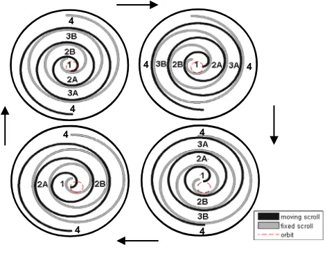
A scroll expander with three wraps in motion and its moving scroll orbit trajectory is illustrated inFig. 4. The black scroll stands
for the moving scroll and the grey one represents the fixed scroll. The moving scroll travels along the orbit anticlockwise when the compressed air comes into the scroll mechanism. During the expander operation, these two scrolls always keep contacting at some points. This forms three different types of air chambers inside the expander shell: a central chamber, even number of sealed crescent chambers and an exhaust chamber. The early work by the authors has proven that the scroll expander has more energy efficient performance compared to conventional pneumatic drives with similar scales (up to several kW level), such as recipro-cating cylinders, vane type air motors, etc.[24].
With the following assumptions: (1) no air leakage, (2) the scroll expander using ideal air and (3) it working at a constant tem-perature environment, a simplified mathematical model for scroll expanders can be derived[22–25]. The geometric model for scroll expanders can be derived from the fundamental curve of a spiral. The equations for the moving scroll can be described by,
xAðus;
a
sÞ ¼x0þ ðq0þj
su
sÞsinu
sþj
scosu
sj
sþrssina
s ð4ÞyAðus;
a
sÞ ¼y0 ðq0þj
su
sÞcosu
sþj
ssinu
sþq
0rscosa
s ð5Þwhereðx0;y0Þis the initial position and
q0
is the initial curvature radius for the moving scroll curve,j
sis the slope of the curvature radius,rsrefers to the orbit radius of the moving scroll,a
sstands for the scroll expander orbit angle,u
sis the tangential angle to the moving scroll. The fixed scroll is generated by the curve which envelops the family of the moving scroll curves when the moving scroll wobbles along with its orbit[22]. The equations for the fixed scroll can be,xBð/sÞ ¼x1 ðq0þ
j
s/sÞsin/sj
scos/sþj
s ð6ÞyBð/sÞ ¼y1þ ðq0þ
j
s/sÞcos/sj
ssin/sq
0 ð7Þwhere/sis the tangential angle to the fixed scroll, (x1,y1) is the initial position for the fixed scroll curve, and the moving scroll
0 5 10 15
0 0.1 0.2 0.3 0.4 0.5
Tip speed ratio
Power coefficient
[image:4.595.320.557.68.157.2]0 degree 5 degree 10 degree 15 degree
Fig. 2.Power coefficients as a function of tip speed ratio and pitch angle.
Fig. 3.Illustration of the scroll expander structure (manufactured by Sanden).
4 4
4
4
4
4
[image:4.595.320.556.194.379.2]4 4
[image:4.595.51.284.648.739.2]contacts the fixed scroll at the points, thus
u
s=/s+jp
,jis an arbi-trary integer[22].Applying Green’s Theorem, the equations for describing the vol-ume variations of the scroll expander chambers can be derived [25]. The control volume of the central chamber is,
VcðasÞ ¼z½ðx0
j
sp
j
2sp
x0rsþrsj
sÞcosa
sþj
2spa
2sþðrs
q
0j
sp
rsq
0y0rsþy0j
spÞ
sina
srsj
sþ13j
2sp
3þðrs
pj
sþ2j
sq
0pÞa
s12rsp
2j
sþq
0rsp
þ12r 2 sp
þq
2 0
p
ð8Þ
whereVc(
a
s) is the volume of scroll expander central chamber,zis the depth of the moving and fixed scrolls. The control volume of theith (i= 1, 2, 3,. . .) pair of sealed crescent chambers is: Vsðas;iÞ ¼z
p
r2sþ2p
rsðq
0þj
sðasþp
þ2ði1ÞpÞÞ
ð9Þ
where Vs(
a
s,i) is the volume of scroll expander sealed crescent chamber volume. The control volume of the exhaust chamber can be described by,VeðasÞ ¼VtotalVcðasÞ X
Vsðas;iÞ ð10Þ
whereVe(
a
s) is the volume of scroll expander exhaust chamber vol-ume, Vtotal represents the total control volume of the scroll expander.From the fundamental of thermodynamics and the theory of orifice, the air pressure of the different scroll expander chambers can be calculated[22–25]. To the air pressure variation of the cen-tral chamberðp_cÞ;
_
pc¼ _
Vc
Vc
pc
x
sc
þ1 Vc
c
RCdC0CkAipsfðpc=psÞ ffiffiffiffiffiTs p
ð11Þ
To the air pressure variation of the first pair of sealed crescent chambersðp_s1Þ;
_
ps1¼ _
Vsðas;1Þ
Vsðas;1Þ
ps1
x
sc
ð12ÞTo the air pressure variation of the second pair of sealed crescent chambersðp_s2Þ;
_
ps2¼ _
Vsðas;2Þ
Vsðas;2Þ
ps2
x
sc
a
s2 ½0;p
ð13ÞTo the air pressure variation of the exhaust chamberðp_eÞ;
_
pe¼ _
Ve
Ve
ps2
x
sc
þ1 Ve
c
Rcdc0ckAopefðpatm=peÞ ffiffiffiffiffiTs p
ð14Þ
The driving torque generated by a scroll expander is the sum of tor-ques on all driving segments on the two scrolls, and it can be derived as[22–25],
s
s¼zr½ð2q0þ2js
a
sþj
spÞð
pcps1Þþð2q0þ2js
a
sþ5jspÞð
ps1ps2Þþð2q0þ2js
a
sþ9jspÞð
ps2peÞa
s2 ½0;p
Zr½ð2q0þ2js
a
sþj
spÞð
pcps1Þþð2q0þ2js
a
sþ5jspÞð
ps1peÞa
s2 ðp;2p8 > > > > > > < > > > > > > : ð15Þ
wherepsis the supply pressure,patmis the pressure of atmosphere,
Tsis the supply temperature,Ris the gas constant,c0= 0.04,cd= 0.8,
ck= 3.864,
c
= 1.4 is the ratio of specific heat,Ai,Aoare the effective area of expander inlet and outlet respectively,rsis the radius of the orbit,x
sis the rotation speed of scroll expander shaft,f() is a func-tion of the ratio between the downstream and upstream pressures at the orifice[24,25]. In the modelling, it should be noticed that, when the orbit anglea
se
(p
, 2p
], the second pair of crescent cham-bers is not sealed anymore in each period (refer toFig. 4).2.3. Mathematical model for permanent magnet synchronous generators
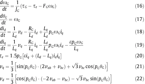
A Permanent Magnet Synchronous Generator (PMSG) has been chosen as the driven machine of the wind turbine; a resistive load is directly connected to the PMSG electricity output for simplicity of analysis. The mathematical model is described by Eqs. (16)– (22), which has been studied in[26–28]:
d
x
Gdt ¼ 1 JG
ðsG
s
eFGx
GÞ ð16ÞdhG
dt ¼
x
G ð17Þdid
dt ¼ 1 Ld
v
dRG
Ld
idþ
Lq
Ld
pG
x
Giq ð18Þdiq
dt ¼ 1 Lq
v
qRG
Lq
iq
Ld
Lq
pG
x
Gide
pGx
GLq ð
19Þ
s
e¼1:5pGe
iqþ ðLdLqÞidiq
ð20Þ
v
q¼1
3 sinðpGhGÞ ð2
v
abþv
bcÞ þffiffiffi
3
p
v
bccosðpGhGÞh i
ð21Þ
v
d¼1
3 cosðpGhGÞ ð2
v
abv
bcÞ ffiffiffi3
p
v
bcsinðpGhGÞh i
ð22Þ
where the subscriptsa,b,c,d,qmean thea,b,c,d,qaxis respec-tively,hGand
x
Gare the PMSG rotor angular position and speed respectively,s
Gands
estand for the PMSG driving and electromag-netic torques,JGis the inertia of the PMSG,RGis the resistance of the stator windings,Lq,Ld are the resultedqandd axis inductances respectively,pGis the number of PMSG pole pairs,iandv
are the current and voltage in the different axes,eis the flux amplitude induced by the permanent magnets of the rotor,FGis combined viscous friction of the generator rotor. The Park’s transformationis employed for transforming X*abc (3-phase coordinates) to X * dq (DQ rotating coordinates)[26,28].
2.4. Mathematical model for the mechanical power transmission
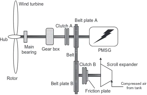
The designed power transmission system mainly includes two electromagnetic clutches and a belt speed transmission to ensure coaxial running, as shown inFig. 5. The functions of two clutches are described below:
(1) Clutch A is engaged in almost all cases. Unless the wind speed is extremely low - under the cut-in wind speed, Clutch A will be disengaged and then the PMSG will be exclusively driven by the scroll expander. For the simplicity of model-ling, the extreme low wind speed (Clutch A disengagement) situation is not considered.
(2) Clutch B is placed to the hybrid system for conditional switching on/off the small-scale CAES subsystem. When the wind turbine cannot generate sufficient electricity to match the electric load demand, the compressed air in the storage tank will be released into the scroll expander via a pneumatic valve and/or regulator’s control; then the scroll expander will start rotating and Clutch B will be engaged at the moment of the expander rotor speed comparably to the wind turbine shaft speed after the belt transmission. Also, Belt plate A and B of the belt transmission have differ-ent diameters to play the function as a gearbox (refer to Fig. 5). Thus the small-scale CAES subsystem and the wind turbine can be integrated rigidly.
[image:5.595.303.554.157.302.2]Case I. Clutch A engaged and Clutch B disengaged: the two disks of Clutch B is fully separated (refer toFig. 5). Considering friction and different payloads, applying Newton’s second law of angular motion, to the shaft of scroll expander, we have,
s
sMfx
s¼ ðJsþJfÞx
_s ð23ÞwhereJsis the scroll expander inertia,Jfis the friction plate inertia,
s
sis the scroll expander driving torque;Mfis the combined viscous friction coefficient;x
_s represents the scroll expander angular acceleration.To the main shaft of the wind turbine system, both the active plate and the passive plate of the belt transmission can be consid-ered as an extra inertia load, thus the total equivalent inertia can be,
Jtotal¼Jpassþ
1
2Jact ð24ÞwhereJpassandJactare the inertias of the passive and active plate respectively,fis the speed ratio of the belt.
Case II. Both Clutch A and Clutch B engaged: Once Clutch B is engaged by coupling its two disks, the following equations can be derived:
s
sMfx
ss
act¼ ðJsþJf þJactÞx
_ss
pass¼s
actg1
s
Hþs
passs
eFGx
G¼x
_GðJGþJpassÞx
s¼x
G1
8 > > > < > > > :ð25Þ
where
s
His the torque of wind turbine speed shaft. The high-speed shaft is linked to the output of gearbox (refer toFig. 5).g
is the transmission efficiency of the belt.2.5. Overall state space model of the hybrid system
With all the subsystem models presented above, the overall state space model for the hybrid system is presented below. The system state variables are chosen:x1: PMSG rotor angle,x2: PMSG angle velocity,x3: current indaxis for PMSG,x4: current inqaxis for PMSG,x5: pressure in the expander central chamber,x6: pres-sure in the expander first pair of crescent chambers,x7: pressure in the expander second pair of crescent chambers,x8: pressure in the expander exhaust chamber; and the input variablesu1: pitch angle,u2: supply pressure for the scroll expander. Integrating the wind turbine, driven train and PMSG sub-models, the state func-tions of the wind turbine system with the engaged CAES can then be described by:
_
x1¼x2 ð26Þ
_
x2¼J 1
GþJpassþJTgT12TþðJsþJfþJactÞg12
hg
T
2x2
q
ap
r 2T
v
3wCpðu1ÞBeq
g
T1
2Tx2þg1ssMfg1
2x21:5pGðex4þLdx3x4Lqx3x4Þ FGx2 ið27Þ
_
x3¼
v
dLd
RG
Ld
x3þ
Lq
Ld
pGx2x4 ð28Þ
_
x4¼
v
q Lq RG Lq x4 Ld LqpGx2x3
e
pGx2Lq
ð29Þ
_
x5¼ _
Vc
Vc
c
x5x2
1
þ1 Vc
c
RCdC0CkAiu2fðx5=u2Þ ffiffiffiffiffiTs p
ð30Þ
_
x6¼ _
Vsðas;1Þ
Vsðas;1Þ
c
x6x2
1
ð31Þ_
x7¼ _
Vsðas;2Þ
Vsðas;2Þ
c
x7x2
1
a
s2 ½0;p
ð32Þ_
x8¼ _
Ve
Ve
c
x8x6
1
þ1 Ve
c
RCdC0CkAox8fðpatm=x8Þ ffiffiffiffiffiTs p
ð33Þ
where
g
TandfTstands for the efficiency and ratio of the turbine shaft transmission,Beqis the equivalent damping coefficient of wind turbine. If the CAES device is disengaged to the wind turbine sys-tem, we have:_
x2¼
1 JGþJpassþJT
g
T1
2Tg
T2x2
q
ap
r 2 Tv
3
wCpðu1Þ Beq
g
T1
2 Tx21:5pGðex4þLdx3x4Lqx3x4Þ FGx2
ð34Þ
withx_5¼x_6¼x_7¼x_8¼0.
3. Control strategy study for the hybrid wind turbine system
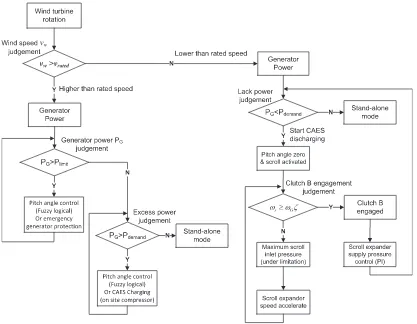
The whole hybrid system consists of several subsystems and has multi-mode operations. Thus it is necessary to develop a set of suitable decision-making rules to switch smoothly between differ-ent modes (e.g., stand-alone wind turbine and hybrid wind turbine integrated with CAES). It is also required to design dynamic control method(s) for the system performance optimization and load balance in each mode operation. The flow chart of the designed multi-mode control strategy for achieving the above objective is illustrated inFig. 6. It can be seen that, for fully regulating the output power of the hybrid system to accurately match the load demand, the control strategy is required to cover all possible situations.
From the flow chart (Fig. 6), the main operation modes are introduced as follows: (1) while the PMSG output power is above its limitation (PG>Plimit), the fuzzy logical control for pitch angle (or emergency generator protection) is adopted; (2) under the high wind speed situations, i.e.,
v
w>v
rated, if the PMSG output power is lower than its limitation but higher than the electric load demand, the fuzzy logical control for pitch angle can be maintained in the hybrid system (or surplus power can be used for CAES subsystem charging if an on-site compressor is available); (3) in the case of the insufficient PMSG output power cannot meet the electric load demand, CAES subsystem discharging mode is activated; when the scroll expander rotor speed reach a certain level, that is,x
sPx
Gf, Clutch B will be engaged and then the scroll expander output tor-que can be used to provide additional driving power to the wind turbine system; in this case, a PI controller is employed to regulate the supply pressure of the scroll expander and in turn to manage the power out of scroll expander; (4) when the PMSG output power roughly matches the electric load demand, the hybrid system will be running on the stand-alone mode, that is, Clutch B will be dis-engaged and the whole system will be in operation with no signal from the controller.Gear box Main
bearing
Belt
Belt plate A
Belt plate B
[image:6.595.49.287.67.221.2]PMSG Scroll expander Clutch B Compressed air from tank Wind turbine Hub Rotor Clutch A Friction plate
Pitch angle adjustment is a common approach to regulate the aerodynamic power extracted by the wind turbine blade, which is the input power of the turbine system. A fuzzy logical controller is introduced to the designed control system for pitch angle adjust-ment to limit the power captured at the high wind speed situations (refer toFig. 6). Fuzzy logic control provides a systematic way to incorporate human experience for controlling a nonlinear system, which is proved to be appropriate to such type of systems [29,30].Fig. 7shows the schematic of pitch angle fuzzy logic con-troller implemented in the hybrid system. Choosing the speed errorVe(difference between the PMSG actual speed and the refer-ence speed), the PMSG actual speed increment Viand the pitch angle control value hp as the linguistic variables. Ve and Vi are inputs of the fuzzy logic controller,hpis the controller output (refer toFig. 7). The linguistic values ofVeandhpare: [NB NM NS ZO PS PM PB], which means negative big, negative middle, negative small, zero, positive small, positive middle, and positive big respec-tively; The linguistic values of Vi are: [N Z P], which stand for
negative, zero and positive. The standard triangular membership functions have been used for both the inputs and the output of the controller. The control law is represented by a set of heuristi-cally chosen fuzzy rules which are given inTable 1.
Based on the triangular membership functions and the fuzzy rules, the designed fuzzy logic controller can produce a crisp and continuous nonlinear input/output map as shown inFig. 8. This map indicates that numerous nonlinearities are designed to enhance the controller’s performance to drive the system to the set point. The details related to using fuzzy logic control specific to adjust the pitch angle of wind turbines can be found in [14,29,30].
[image:7.595.85.502.65.389.2]During the low wind speed periods, the CAES device will work at the discharging mode to provide additional driving power. For controlling the input power from the CAES device to the wind tur-bine system, it is necessary to manage how much compressed air flows into the scroll expander at every moment. Considering the limited central chamber volume of the scroll expander, the supply
Fig. 6.Multi-mode control diagram for the proposed hybrid system.
Wind speed input
System connection
Monitoring/Control signal
Clutch A engaged, Clutch B disengaged
PMSG Power
transmission Wind turbine
Fuzzy logic controller Pitch angle
control signal
Increment
Generator speed monitoring
PMSG speed ref.
[image:7.595.131.454.636.736.2]air pressure control by a digital proportional pressure regulator is more suitable to achieve this purpose, compared to the traditional pneumatic valve displacement control. A PI control method on the pressure regulator is chosen because of its simplicity.Fig. 9shows the schematic of the scroll expander supply pressure PI control. The controller input is the PMSG speed tracking errore(t), i.e.,
e(t) =
x
refx
G, wherex
refis the PMSG reference speed. The con-trol law can be represented as:UðtÞ ¼KPeðtÞ þKI Z
eðtÞ þCinitial ð35Þ
where KP andKIare the proportional and integral control gains,
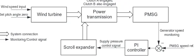
Cinitialrepresents the initial controller reference value. In addition, during the low wind speed periods, it is common to set the pitch anglehequals to zero for achieving the best turbine efficiency Cp (refer to Section2.1andFig. 9).
4. Simulation study for the hybrid system
The overall state space model of the hybrid wind turbine with the CAES system and its corresponding multi-mode control strategy are implemented in Matlab/Simulink environment for
simulation study. The parameters for the simulation study of the whole hybrid system are listed inTable 2. Most parameters related to the scroll expander, the drive train and the PMSG are obtained from the associated data sheets or measurement of the machines which are used for building the experimental test rig in the labora-tory. However, due to the complicated structure of the hybrid system, sometimes it is difficult to obtain the precise values for all parameters. These unknown parameters for models can be iden-tified using intelligent computational algorithms together with the experimental data[31].
The simulation considers the scenario when the input mean wind speed steps down within a 40 s time series observation win-dow, as shown inFig. 10. A white noise source with a shaping filter is chosen to generate the input wind speed profile, and its feasibil-ity had been studied in[32–34]. FromFig. 10, it can be seen that the mean wind speed drops from around 10 m/s to 8 m/s at the moment of the 20th second. Thus the simulated data can represent the wind speed variation in a certain period.
[image:8.595.42.292.84.354.2]Introducing the simulated wind speed profile given inFig. 10to the hybrid system input,Fig. 11shows the comparisons of dynamic responses of the multi-mode controlled hybrid system and the stand-alone wind turbine system without any controller imple-mentation, which include the variation history comparisons of the PMSG speeds and the wind turbine main shaft torques. To a given electric resistance load, the PMSG reference speed is set to 190 rad/s. FromFig. 11, it is clearly seen that, during low wind speed periods, the PMSG can obtain additional driving torque from small-scale CAES integration, thus the simulated hybrid system with the PI controller connected can compensate the required elec-tric power efficiently; meanwhile, during high wind speed periods, the designed system with the fuzzy logic controller activated can track the reference speed very well, which may reveal only few extra load and tiny inertia added by the mechanical power trans-mission. Furthermore, it looks that the performance of PI control to the scroll expander supply pressure is not as good as that of the pitch angle fuzzy logic control. This could be resulted from the high nonlinearity characteristics of the compressed air.
Table 1
Rule base for proposed fuzzy controller.
hp Vi
N Z P
Ve NB PB PB PM
NM PB PM PS
NS PM PS ZO
ZO PS ZO NS
PS ZO NS NM
PM NS NM NB
PB NM NB NB
Fig. 8.Fuzzy logical controller nonlinear input & output map.
Wind speed input
System connection
Monitoring /Control signal
Clutch A engaged, Clutch B also engaged
PMSG Power
transmission Wind turbine
PI controller
Generator speed monitoring
PMSG speed ref. Set pitch angle zero
Scroll expander
[image:8.595.311.561.86.226.2]Supply pressure control signal
Fig. 9.Schematic of the scroll expander supply pressure PI control.
Table 2
Parameters of the hybrid wind turbine system.
Symbol Description Value
JT Inertia of turbine blades 4.9 kgm2
qa Air density 1.25 kg/m3
rT Blade radius 1.75 m
fT Speed ratio of turbine shaft transmission 5
gT Efficiency of turbine shaft transmission 95%
g Transmission efficiency of the belt 95%
rs Orbit radius of the scroll 5.40103m
z Depth of the scroll chambers 3.33102
m
Vtotal Total control volume of the scroll 2.50104
m3
pG The number of pole pairs 6
RG Resistance of the PMSG stator windings 1.31 Ohm
Ld Inductance on d axis 2.075 mH
Lq Inductance on q axis 2.075 mH
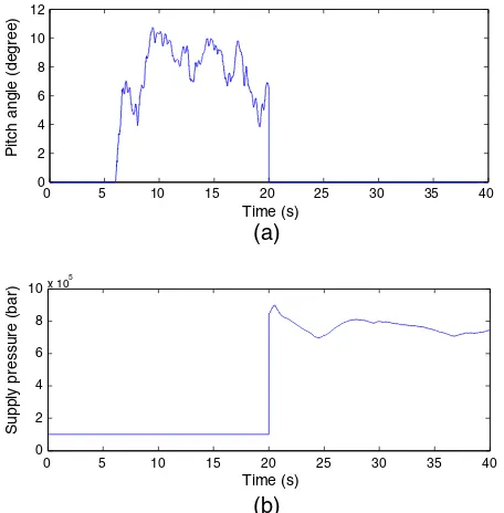
[image:8.595.140.464.646.739.2]Correspondingly,Fig. 12 shows the simulation results of the dynamic responses of the controlled variables in the hybrid system when the input wind speed profile is given as Fig. 10. In the designed system, the pitch angle and the supply pressure of the
[image:9.595.42.276.66.158.2]scroll expander are the controlled variables. FromFig. 12(a), it can be observed that, under the conditions of high wind speed, the pitch angle varies within the range from 0° to 11°. This is because the pitch angle is adjusted by fuzzy logic control to main-tain a relatively steady wind power output for the PMSG speed get-ting close to the required reference (190 rad/s). At low speed situations, the pitch angle is set to 0 degree for maximizing the capability of wind turbine blades to extract the wind energy. In Fig. 12(b), the variation history of the supply pressure of scroll expander is presented. The expander is activated at 20 s from the time at which the wind turbine are in operation. Once Clutch B is engaged, its supply pressure is always managed by the designed PI controller. From the simulation study, the scroll expander can speed up very quickly after its activation, mainly due to the expan-der small inertia.
5. Experimental tests
An experimental test rig corresponding to the designed hybrid system is built in the authors’ research laboratory at the University of Warwick, as shown inFig. 13. The block diagram of this proto-type test rig is illustrated inFig. 14. Due to the limitation of indoor laboratory work, the test rig uses a ‘‘Wind Turbine Simulator (WTS)’’ to replace the practical wind turbine blade, which consists of dual DC motors, their power supplies and some auxiliaries (Fig. 14). The function of this simulator is to mimic the real fluctu-ant turbine blade torque and wind power scenario. The reasonabil-ity of WTS had been proven in some literatures, e.g.,[32,33].
Based onFig. 14, the main test system components are listed in Table 3. The test rig consists of duel DC motors, a PMSG and its 3-phase resistance load, a scroll expander, a compressed air stor-age tank, a belt transmission subsystem, two clutch mechanisms, two gear sets, a pneumatic valve, a digital pressure regulator, DC power supplies, sensors and meters for electrics and pneumatics, etc. The employed scroll expander is modified from a scroll com-pressor (Table 3). In addition, two gears sets (Fig. 14) as speed match devices are applied to ensure that each facility can work around at its rated condition. The speed ratios to the gear sets are determined by the rated speeds of these facilities.
A dSPACE real-time controller (Model: RTI1104) is chosen for collecting the experimental data from electric and pneumatic sen-sors. The experimental data is monitored and collected in dSPACE Controldesk/Matlab environment. This real-time controller is also used for controlling the whole hybrid system operations, which include activating the scroll expander, engaging Clutch B (Clutch A is always engaged as described in Section2), implementing PI
0 5 10 15 20 25 30 35 40
0 2 4 6 8 10
Time (s)
[image:9.595.43.275.67.415.2]Wind speed (m/s)
Fig. 10.Simulated wind speed profile.
0 5 10 15 20 25 30 35 40
0 50 100 150 200 250
Time (s)
Generator velocity (Rad/s)
(a) Comparision of simulated PMSG speeds
Stand-alone Controlled hybrid 190
0 5 10 15 20 25 30 35 40
0 2 4 6 8 10 12
Time (s)
Shaft torque (N*m)
(b) Comparision of simulated wind turbine main shaft torques
[image:9.595.45.273.449.681.2]Stand-alone Controlled hybrid
Fig. 11.Comparison of dynamic responses of the hybrid system with designed controllers connected and the stand-alone wind turbine without any control.
0 5 10 15 20 25 30 35 40
0 2 4 6 8 10 12
Time (s)
Pitch angle (degree)
(a)
0 5 10 15 20 25 30 35 40
0 2 4 6 8 10x 10
5
Time (s)
Supply pressure (bar)
(b)
[image:9.595.306.549.571.734.2]Fig. 12.Dynamic responses of the controlled variables in the hybrid system.
control to the pressure regulator and managing the WTS torque output to the hybrid system (refer toFig. 14).
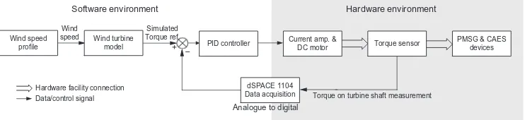
Fig. 15illustrates the block diagram of the WTS in the hybrid system test rig. The WTS can be considered as a variant of Rapid Control Prototyping (RCP) – using simple PID control to command
duel DC motors for mimicking the real wind turbine behaviours. Similarly to the simulation study, a white noise source with a shap-ing filter is used to generate the wind speed profile ([32–34]). A typical torque-current closed loop PID control is implemented on the DC motors as shown inFig. 15.
The comparisons of the experimental test results and the simu-lated data for the WTS are given inFig. 16, including the wind tur-bine shaft speeds and torques respectively. It can be seen that the experimental dynamic performance of the WTS torque can track well to that of the simulated torque reference. From the experi-mental tests, it is proven that the WTS can meet the laboratorial requirements to mimic the practical scenarios of wind power gen-eration systems.
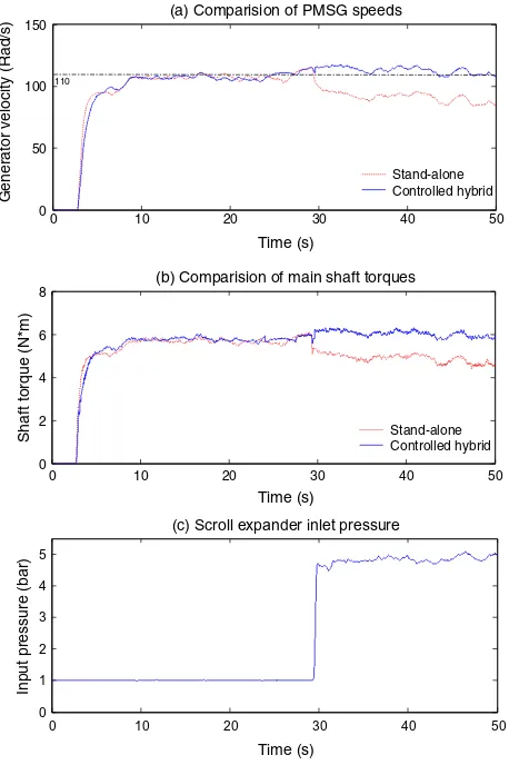
Due to the laboratory limitations and the university safety regulations, the experimental test to the hybrid system with the control strategy implemented mainly focuses on the study of sys-tem operation under low wind speed situations. It is for observing the test rig dynamic responses at the moment of Clutch B engage-ment and the controller performance to the CAES subsystem for compensation work.Fig. 17shows the comparisons of the experi-mental test results of the hybrid system under the wind turbine stand-alone mode and the wind turbine integrated CAES with con-troller connected mode. The speed reference is set to 110 rad/s. It can be seen that, with the CAES integration and the scroll expander supply pressure control, the designed experimental test system
DC motor
Torque sensor
PMSG
2 4
4
Inertia plate
Wind Turbine SImulator (WTS)
expander
Scroll
Belt transmission
1
Clutch B
8 Current amplifier
Rated 10A
DC power supply DC power
supply
Matlab/Controldesk
dSPACE 1104
DC current command signal
DC motor
3 phase resistance load
3
8
Pressure regulator
Proportional valve
DC power supply 20V
Relay Relay control
signals Pressure regulator control signal
Univ. air supply
Storage tank
DC power supply 10V
Max 6bar air supply Current amplifier
Rated 10A
Gear set
Gear set
Mechanical shaft Compressed air pipe Control signal Electric wire/cable
Clutch A
Relay
[image:10.595.42.293.383.547.2]Fig. 14.Block diagram of the test rig of the wind turbine system integrated with small-scale CAES.
Table 3
Machines for the experimental test system.
Name Serial number/description Manufacturer
DC motor SN:M4-2952X-2100t-000 Callan Tech.
PMSG SN:SGMSS-20A Yaskawa Elec.
Scroll expander Modified from scroll compressor TRSA090 Sanden
Air tank Max 6 bar due to univ. safety regulation BOC UK
Controller Model: RTI1104 dSPACE
Clutch A SN:CS-10-31G, 24V Mikipulley
Clutch B SN:101-10-15G, 24V Mikipulley
DC power supply 90Vdc, 0-10Adc, for DC motor TRM Elec.
DC amplifier SN:10/100, 24-100Vdc, 0-10Adc TRM Elec.
Voltage transducer SN:LV 25-P,±10V LEM
Current transducer SN:LTSR 15-NP,±15A LEM
Pressure sensor SN:SDE1-D10-G2-W18-L-PU-M8 FESTO
Flow meter SN:MS6 SFE-F5-P2U-M12 FESTO
Pressure regulator SN:VPPM-6L-L-1-G18-0L10H-V1N FESTO
Pneumatic valve SN:MYPE-5-1/4-010-B, 0-10 bar FESTO
Torque sensor SN:RWT 310, 0-2000 RPM Sensor Tech.
Temperature sensor K-type thermocouple RS UK
Torque on turbine shaft measurement Wind turbine
model Wind speed
profile
PMSG & CAES devices Current amp. &
DC motor Torque sensor
Software environment Hardware environment
Analogue to digital Wind
speed
Hardware facility connection Data/control signal
PID controller
dSPACE 1104 Data acquisition Simulated
[image:10.595.117.488.649.734.2]Torque ref.
can maintain relatively steady outputs and to meet the speed ref-erence under the low wind speed conditions. The CAES system can contribute controllable mechanical power to the hybrid wind turbine system for generating required electricity. Thus the exper-iment results shown inFig. 17verify that the idea proposed in this paper is feasible and the corresponding prototype can work properly.
6. Efficiency analysis
To the situation of controlled hybrid system operation, the power transmission and conversion from a small-scale CAES to the wind turbine system is schematically illustrated inFig. 18. The scroll expander converts the energy extracted from the stored compressed air into the useful mechanical energy which is in turn transferred to the wind turbine main shaft through the belt trans-mission system. For such process, energy losses are inevitable, such as the scroll expander operation loss due to friction, vibration, air leakage, lubricant viscosity, etc.
The power efficiency of the engaged CAES system in this paper is defined as,
g
eff¼Increased mechanical power resulted from CAES compensation Input compressed air power from CAES
ð36Þ
This power efficiency reveals the performances of the designed small-scale CAES facility and the mechanical power transmission. In addition, the increased mechanical power resulted from CAES compensation is considered as the difference of the hybrid system main shaft powers between the stand-alone mode and hybrid mode under the same driving conditions.
From the above description, it is necessary to quantitatively analysis how much air power/energy carried by compressed air enters into the scroll expander. One simplified approach is adopted for calculating the input air power referred to STP (Standard Tem-perature and Pressure, 0°C at 1 bar), which is ([35,36]):
_
Qin¼m_inRTatm ln pin
patm
þ k
k1 Tin
Tatm
1ln Tin Tatm
ð37Þ
whereQ_inis the input air power to the scroll expander,m_inis the input air mass flow rate,Tis temperature,pis pressure,kis the spe-cific heat ratio, subscriptatm means atmospheric state andin is inlet thermodynamic state. When the environment shifts 100 K from the atmospheric temperature, the temperature variation to the change of air power is limited ([35,36]). Thus it can assume
Tin=Tatm and then substituting this into Eq. (37), the air power can be calculated by,
0 10 20 30 40 50
0 20 40 60 80 100 120 140
Time (s)
Generator velocity (Rad/s)
(a) Comparision of simulated and experimental speeds
Simulated Experimental
Simulated
0 10 20 30 40 50
0 2 4 6 8
Time (s)
Shaft torque (N*m)
(b) Comparision of simulated and experimental torques
[image:11.595.45.275.66.331.2]Simulated Experimental
Fig. 16.Comparisons of the test results and the simulated data for the WTS.
0 10 20 30 40 50
0 50 100 150
Time (s)
Generator velocity (Rad/s)
(a) Comparision of PMSG speeds
Stand-alone Controlled hybrid 110
0 10 20 30 40 50
0 2 4 6 8
Time (s)
Shaft torque (N*m)
(b) Comparision of main shaft torques
Stand-alone Controlled hybrid
0 10 20 30 40 50
0 1 2 3 4 5
Time (s)
Input pressure (bar)
(c) Scroll expander inlet pressure
Fig. 17.Experimental test results of the stand-alone wind turbine and the controlled hybrid system.
Scroll input air power from CAES
Scroll operation loss
Scroll exhaust power loss
Scroll output useful power
Compensated mechanical power to wind turbine main shaft
[image:11.595.45.274.388.732.2]Mechanical transmission loss
[image:11.595.306.549.576.730.2]_
Qin¼m_inRTatmln
pin
patm
¼patmwinln
pin
patm
ð38Þ
wherewinis the input volumetric air flow rate.
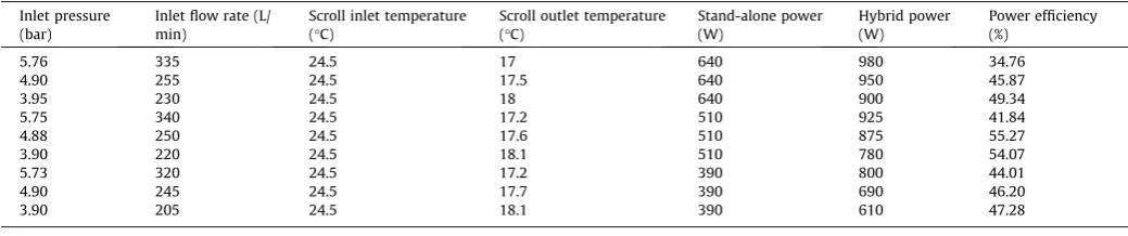
Building upon the available sensors in the laboratory for data acquisition, three groups of experimental tests of the hybrid sys-tem are implemented to analyse the power efficiency. The experi-mental results are given inTable 4. The tests are conducted under the condition of maintaining the Wind Turbine Simulator (WTS) power output at three different levels, which result in three mea-sured power levels of shaft power under the wind turbine stand-alone mode, which are 640, 510 and 390 W respectively (Table 4). Also, in each group of the tests, the hybrid system is operated at the different inlet air pressures to the scroll expander for the power efficiency comparison.
From the experimental results, it can be found that, in each group of the tests, the variations of the power efficiency are rele-vant to the scroll expander inlet air pressure, which indicates that the air pressure and mass flow rate should be well managed and controlled to achieve higher efficiency. According to this, under a given working condition, it may suggest using lower inlet pres-sures of compressed air for obtaining higher power efficiencies. FromTable 4, the maximum power efficiency is around 55%. The main reason for this moderate efficiency is that CAES and pneu-matic drives have relatively low efficiencies in general. From the reported figures, in most cases, around 20–30% energy efficiency can be achieved for pneumatic actuator (drive) systems; 45–54% cycle efficiency has been reported for the existing commercialized large-scale CAES plants[9,22,35,36]. Although the scroll expander has relatively higher energy conversion ability compared to tradi-tional pneumatic actuators ([23,24]), the efficiency related to CAES and its components is still a key issue which needs further research and development. Also, considering the moderate efficiency of CAES and pneumatic drives, the power efficiency analysis indicates that the designed mechanical power transmission for the hybrid system can obtain an acceptable performance.
8. Conclusion
In this paper, a new concept of hybrid system is proposed, which consists of a kW-level wind turbine integrated with a small-scale CAES unit. To avoid mechanical force coupling between the torques from wind power and the air expander, a mechanical transmission mechanism is developed to smoothly integrate the two torques. The complete dynamic mathematical model of the hybrid system is developed and implemented in Matlab/Simulink simulation environment for comprehensive simulation study of system dynamic behaviours. An appropriate control strategy is developed for the system to smooth the transient fluctuations and compensate the energy gap of wind power generation. A pro-totype system is built and installed in the research lab for verifying the design idea. From both the simulation and test results, the
hybrid wind turbine system can generate reliable steady power output with the compensation from CAES. It can be concluded that the proposed hybrid system of wind turbine and CAES is feasible with a great potential for future industrial applications.
The energy conversion efficiency from the compressed air energy to the electrical power output has been investigated with various operation conditions. The system test results indicated that the efficiency can be up to 55% under a well-controlled operation condition, which is higher than the typical pneumatic actuator effi-ciency. The findings have provided essential evidences and infor-mation for the next stage of research which will lead to the hybrid system with improved efficiency and reliability.
Acknowledgement
The authors would like to thank Advantage West Midlands and the European Regional Development Fund, funders of the Science City Research Alliance Energy Efficiency Project – a collaboration between the Universities of Birmingham and Warwick and UK Engineering and Physical Sciences Research Council (EPSRC, EP/ K002228/1) for the funding support.
References
[1] Global Wind Energy Council. Global statistics n.d. <http://www.gwec.net/ global-figures/graphs/>. [Accessed: 16- Feb – 2014].
[2]Gul T, Stenzel T. Intermittency of wind: the wider picture. Int J Glob Energy Issues 2006;25:163–86.
[3]Roy S. Impact of short duration wind variations on output of a pitch angle controlled turbine. Sustain Energy, IEEE Trans 2012;3:566–75.
[4] Houwing M, Papaefthymiou G, Heijnen PW, Ilic MD. Balancing wind power with virtual power plants of micro-CHPs. PowerTech, 2009 IEEE Bucharest, IEEE; 2009. p. 1–7.
[5]Chen Z, Guerrero JM, Blaabjerg F. A review of the state of the art of power electronics for wind turbines. Power Electron IEEE Trans 2009;24:1859–75. [6]Díaz-González F, Sumper A, Gomis-Bellmunt O, Villafáfila-Robles R. A review of
energy storage technologies for wind power applications. Renew Sustain Energy Rev 2012;16:2154–71.
[7]Le HT, Santoso S. Operating compressed-air energy storage as dynamic reactive compensator for stabilising wind farms under grid fault conditions. IET Renew Power Gener 2013;7:717–26.
[8]Cavallo A. Controllable and affordable utility-scale electricity from intermittent wind resources and compressed air energy storage (CAES). Energy 2007;32:120–7.
[9] Succar S, Williams RH. Compressed air energy storage: Theory, Resources And Applications For Wind Power, 2008.
[10] Sun H, Luo X, Wang J. Management and control strategy study for a new hybrid wind turbine system. In: IEEE Conf. Decis. Control Eur. Control Conf., IEEE; 2011. p. 3671-76.
[11] RWE power. ADELE – Adiabatic compressed-air energy storage (CAES) for electricity supply n.d. <http://www.rwe.com/web/cms/en/365478/rwe/ innovation/projects-technologies/energy-storage/project-adele/>. [Accessed: 07-Nov-2012].
[12] Finkenrath M, Pazzi S, D’ercole M, Marquardt R, Moser P, Klafki MZS. Status and Technical Challenges of Advanced Compressed Air Energy Storage (CAES) Technology. 2009 Int. Work. Environ. Altern. Energy, Monachium, 2009. [13] Yang Y, Emadi A. Integrated electro-mechanical transmission systems in
[image:12.595.42.562.86.195.2]hybrid electric vehicles, IEEE, 2011.
Table 4
Power efficiency analysis based on the experimental data.
Inlet pressure (bar)
Inlet flow rate (L/ min)
Scroll inlet temperature (°C)
Scroll outlet temperature (°C)
Stand-alone power (W)
Hybrid power (W)
Power efficiency (%)
5.76 335 24.5 17 640 980 34.76
4.90 255 24.5 17.5 640 950 45.87
3.95 230 24.5 18 640 900 49.34
5.75 340 24.5 17.2 510 925 41.84
4.88 250 24.5 17.6 510 875 55.27
3.90 220 24.5 18.1 510 780 54.07
5.73 320 24.5 17.2 390 800 44.01
4.90 245 24.5 17.7 390 690 46.20
[14]Madlener R, Latz J. Economics of centralized and decentralized compressed air energy storage for enhanced grid integration of wind power. Appl Energy 2013;101:299–309.
[15]Marano V, Rizzo G, Tiano FA. Application of dynamic programming to the optimal management of a hybrid power plant with wind turbines, photovoltaic panels and compressed air energy storage. Appl Energy 2012;97:849–59.
[16]Succar S, Denkenberger DC, Williams RH. Optimization of specific rating for wind turbine arrays coupled to compressed air energy storage. Appl Energy 2012;96:222–34.
[17]Li Y, Wang X, Li D, Ding Y. A trigeneration system based on compressed air and thermal energy storage. Appl Energy 2012;99:316–23.
[18]Heier S. Grid integration of wind energy conversion systems. Wiley; 1998. [19]Sun H, Wang J, Guo S, Luo X. Study on energy storage hybrid wind power
generation systems. Proc World Congr Eng 2010:833–8.
[20] Mathworks. Matlab R2012a Documentation-SimPowerSystems n.d. <http:// www.mathworks.co.uk/help/physmod/sps/powersys/ref/windturbine.html/>. [Accessed: 31-Oct- 2013].
[21]Mihet-Popa L, Blaabjerg F, Boldea I. Wind turbine generator modeling and simulation where rotational speed is the controlled variable. Ind Appl IEEE Trans 2004;40:3–10.
[22]Wang J, Yang L, Luo X, Mangan S, Derby JW. Mathematical modeling study of scroll air motors and energy efficiency analysis—Part I. Mechatronics. IEEE/ ASME Trans 2011;16:112–21.
[23] Yanagisawa T, Fukuta M, Ogi Y, Hikichi T. C591/027/2001 Performance of an oil-free scroll-type air expander. In: IMechE Conf. Trans., vol. 7, Professional Engineering Publishing; 1998; 2001. p. 167–76.
[24]Wang J, Luo X, Yang L, Shpanin LM, Jia N, Mangan S, et al. Mathematical modeling study of scroll air motors and energy efficiency analysis-Part II. Mechatronics. IEEE/ASME Trans 2011;16:122–32.
[25] Yang L, Wang J, Lu N, Mangan S, Derby JW. Energy efficiency analysis of a scroll-type air motor based on a simplified mathematical model. Proc. World Congr. Eng. 2007, London, 2007.
[26] Dehkordi AB, Gole AM, Maguire TL. Permanent magnet synchronous machine model for real-time simulation. Int. Conf. power Syst. transients, 2005. [27] Fitzgerald AE, Kingsley C, Umans S. Electric Machinery, 6/e. Ed; 1983. [28] Pillay P, Krishnan R. Modeling, simulation, and analysis of permanent-magnet
motor drives. I. The permanent-magnet synchronous motor drive. vol. 25. 1989. [29]Chen WL, Hsu YY. Unified voltage and pitch angle controller for wind-driven induction generator system. Aerosp Electron Syst IEEE Trans 2008;44:913–26. [30]Chowdhury MA, Hosseinzadeh N, Shen W. Fuzzy logic systems for pitch angle controller for smoothing wind power fluctuations during below rated wind incidents. PowerTech IEEE Trondheim IEEE 2011;2011:1–7.
[31]Wei J-L, Wang J, Wu QH. Development of a multisegment coal mill model using an evolutionary computation technique energy conversion. IEEE Trans 2007;22:718–27.
[32]Nichita C, Luca D, Dakyo B, Ceanga E. Large band simulation of the wind speed for real time wind turbine simulators. IEEE Trans Energy Convers 2002;17:523–9.
[33] Li W, Xu D, Zhang W, Ma H. Research on wind turbine emulation based on DC motor. In: Ind. Electron. Appl. 2007. ICIEA 2007. 2nd IEEE Conf., IEEE; 2007. p. 2589–93.
[34]Welfonder E, Neifer R, Spanner M. Development and experimental identification of dynamic models for wind turbines. Control Eng Pract 1997;5:63–73.
[35]Cai M, Kagawa T. Energy consumption assessment of pneumatic actuating systems including compressor. London, UK: Int. Conf. Compressors their Syst; 2001. p. 381–90.